Publisher’s version / Version de l'éditeur:
Arctic Technology Conference, 2016-10
READ THESE TERMS AND CONDITIONS CAREFULLY BEFORE USING THIS WEBSITE. https://nrc-publications.canada.ca/eng/copyright
Vous avez des questions? Nous pouvons vous aider. Pour communiquer directement avec un auteur, consultez la
première page de la revue dans laquelle son article a été publié afin de trouver ses coordonnées. Si vous n’arrivez pas à les repérer, communiquez avec nous à [email protected].
Questions? Contact the NRC Publications Archive team at
[email protected]. If you wish to email the authors directly, please see the first page of the publication for their contact information.
Archives des publications du CNRC
This publication could be one of several versions: author’s original, accepted manuscript or the publisher’s version. / La version de cette publication peut être l’une des suivantes : la version prépublication de l’auteur, la version acceptée du manuscrit ou la version de l’éditeur.
For the publisher’s version, please access the DOI link below./ Pour consulter la version de l’éditeur, utilisez le lien DOI ci-dessous.
https://doi.org/10.4043/27430-MS
Access and use of this website and the material on it are subject to the Terms and Conditions set forth at Ice model tests for dynamic positioning vessel in managed ice Wang, Jungyong; Sayeed, Tanvir; Millan, David; Gash, Robert; Islam, Mohammed; Millan, James
https://publications-cnrc.canada.ca/fra/droits
L’accès à ce site Web et l’utilisation de son contenu sont assujettis aux conditions présentées dans le site LISEZ CES CONDITIONS ATTENTIVEMENT AVANT D’UTILISER CE SITE WEB.
NRC Publications Record / Notice d'Archives des publications de CNRC:
https://nrc-publications.canada.ca/eng/view/object/?id=bc9b6970-4859-4812-b0bf-035dd51b803a https://publications-cnrc.canada.ca/fra/voir/objet/?id=bc9b6970-4859-4812-b0bf-035dd51b803a
OTC-27430-MS
Ice Model Tests for Dynamic Positioning Vessel in Managed Ice
Jungyong Wang, Tanvir Sayeed, David Millan, Robert Gash, Mohammed Islam and James Millan / Ocean, Coastal and River Engineering of National Research Council Canada, (OCRE-NRC)
Copyright 2016, Offshore Technology Conference
This paper was prepared for presentation at the Arctic Technology Conference held in St. John’s, Newfoundland and Labrador, 24-26 October 2016.
This paper was selected for presentation by an ATC program committee following review of information contained in an abstract submitted by the author(s). Contents of the paper have not been reviewed by the Offshore Technology Conference and are subject to correction by the author(s). The material does not necessarily reflect any position of the Offshore Technology Conference, its officers, or members. Electronic reproduction, distribution, or storage of any part of this paper without the written consent of the Offshore Technology Conference is prohibited. Permission to reproduce in print is restricted to an abstract of not more than 300 words; illustrations may not be copied. The abstract must contain conspicuous acknowledgment of OTC copyright.
Abstract
Stationkeeping in managed ice using dynamic positioning (DP) control system has been an area of great interest over the past few years. The stationkeeping performance of a DP vessel depends on the
modelling accuracy of the ice forces, which in turn depends on managed ice field characteristics (floe size, floe thickness, inclusion of brash ice and small ice pieces, ice drift speed and direction) and DP system (gain set-ups). Over the years, many engineers have been using numerical and experimental tools to assess the effect of these parameters. More recently, a comprehensive series of experiments with a 1/40 scaled DP vessel were conducted in various realistic managed ice conditions in the ice tank facility of OCRE-NRC in early 2015.
This paper describes the preparation of managed ice field, the procedure of the model tests and the methodologies of data analysis. The physical and mechanical characteristics of the ice field were modelled by controlling ice concentration, ice thickness, floe size, ice strength and ice drift
speed/direction. The ice concentration ranged from light condition (6/10th) to very heavy condition (9/10th+) with three different floe sizes (100m, 50m and 25 m). Three different ice thicknesses (0.6m, 1.2m and 2m) were used and three different drift speeds (0.2 kts, 0.5 kts, and 1.2 kts) with various heading angles were tested. Some tests used high strength model ice in order to keep the ice field longer (sometimes for 2nd day). Some tests used properly scaled model ice (700 kPa of flexural strength in full scale) in order to simulate ice failure appropriately. Ice loads were not directly measured but estimated based on the thrusters’ response. Video analysis is introduced and some observations are described. Test results for a few cases are presented as an example.
1.0 Introduction
Much of the new hydrocarbon resources in the Arctic are found in water too deep to be economically feasible for fixed structures. Currently, DP controlled and/or moored floating systems are the only realistic option for drilling and exploration services as practical techniques for subsea drilling
technology have yet to be developed. This means the stationkeeping technology of the floating system must withstand the loads placed by the dynamic nature of ice, otherwise it may force structure off its location, and in extreme cases these forces may cause structural damage. In order for the floating system
to operate in a desired location in the Arctic, a feasibility study is required to evaluate the sustainable ice loads and corresponding ice management requirements. A prior knowledge of the expected ice loads appears beneficial in designing both the floating system and the stationkeeping system.
DP systems in the market today do not take account for the forces and moments that exist in the ice environment and it is these input variables that will be required for future DP operations in the Arctic. The current challenges for industry thus are to provide a capability to dynamically positioning systems in level and managed ice fields and at the same time design such structures that withstand the ice– structure interaction loads at the sea surface. Consensus has been achieved within the relevant industry that understanding and modeling the dynamic interactions between these parameters and the station-keeping vessel are the keys for effective and reliable DP operations. A knowledge gap has been
identified in the understanding of the magnitude and nature of ice forces encountered by the DP systems operating in the managed ice fields. Physical model testing for DP controlled structures in simulated ice fields is perhaps the primary and realistic option to obtain understanding to the loads on the structure in the challenging environments. Although full scale trials are the most preferred approach of gathering information on ice loads, these are considered very expensive with poor control over the ice conditions and require highly complex instrumentation.
OCRE-NRC, Canada conducted DP model tests in managed ice using a generic drillship in 2011 (Millan and Wang, 2011; Gash and Millan, 2012). During these tests, a real time capable machine vision system was used to observe ice floe accumulation around the vessel. A three year project Dynamic Positioning in Ice (DYPIC) was led by the Hamburg Ship Model Basin (HSVA) and funded by the National
Research Agencies of Germany, France and Norway during 2010-2012 (Jenssen et al., 2012, Kerkeni et al., 2014). The backbone of DYPIC consisted of extensive model tests conducted by HSVA in various ice conditions. Kjerstad et al. (2014) identified two major phenomena – ice floe contact network and accumulated ice mass caused ice load variation. In 2011, another DP model test was conducted by HSVA using a ship model, the Arctic drillship Stena Drillmax in managed ice including brash ice (Hals and Efraimsson, 2011). The effect of brash ice was found to smooth out the ice loads.
Most recently, the Centre for Marine Simulation at the Fisheries and Marine Institute of Memorial University, with its technical partner, the National Research Council and commercial partner, the Kongsberg Maritime Simulation Ltd (KMS), initiated a five year research and development project aiming to develop dynamic positioning system technologies specifically for ice-rich environments (Islam et al., 2016). A comprehensive series of experiments with a 1/40 scaled DP vessel were conducted in various realistic managed ice conditions in the ice tank facility of OCRE-NRC in early 2015. This paper is focused on the DP model testing in the ice tank in managed ice.
2.0 Test Facility and Model Instrumentation
2.1 Ice tank and model iceThe useable area of the tank for ice testing is 76 m long, 12 m wide and 3 m deep. In addition, a 15 m long setup area is separated from the ice sheet by a thermal door to allow equipment preparation while the test ice sheet is prepared, as shown in Figure 1. The towing carriage is an 80 ton steel structure and the range of operating speed is from 0.0002 to 4.0 m/s. The test frame of the carriage can move
transversely and vertically in order to control the test position. The service carriage is an independent hydraulically operated unit and it is useful for ice control and sampling.
The EGADS model ice prepared in the ice tank at OCRE-NRC has been developed to provide the kinematic and mechanical characteristics required to model the ship-ice interaction correctly. It is a dilute aqueous solution of ethylene glycol (EG), aliphatic detergent (AD) and sugar (S) in the
approximate ratio 0.39/0.036/0.04%. Glycol is the principal ingredient and its function is to reduce the strength of ice. After the ice has been grown to approximately the desired thickness, the air temperature is raised to a little over freezing. During this tempering period the ice warms and the entrapped glycol pockets within the ice slowly melt the surrounding crystal structure, thereby weakening the ice strength.
Figure 1: Ice tank at NRC
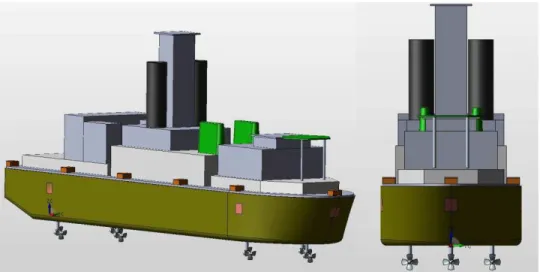
2.2 Model configuration and test set up
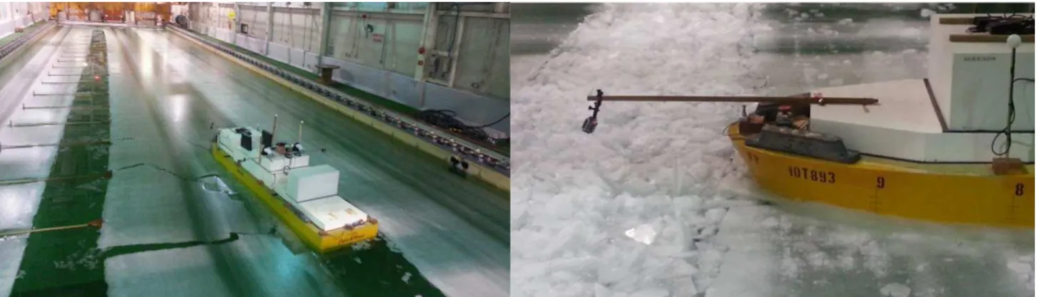
For the experimental program, a generic model hull was outfitted as per NRC’s standard procedures. The model was marked with one waterline (loaded condition at 12.0 m FS draft). The model was
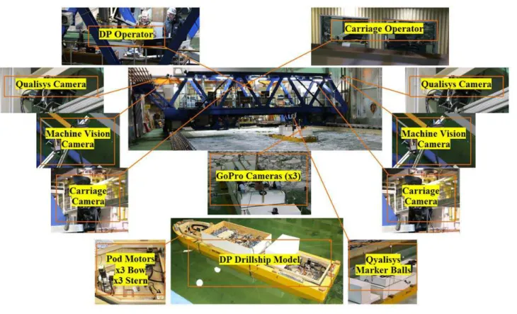
equipped with a fully functional dynamic positioning system with 6 active thrusters (podded propulsors), see Figure 2. Figure 3 shows the test set up. During the tests, the model was placed in front of the main carriage and set point was on the carriage. Instead of moving the managed ice field, the carriage with a set point was moving through the stationary ice field. The model was then dynamically positioned with the moving set point. An optical tracking system (QualisysTM) tracked the model and measured the motion. The shaft speed of each of the six thrusters was measured in revolution per section (RPS). 2 High Definition carriage cameras, 2 machine vision cameras and 3 portable cameras were used to record entire test. Two carriage cameras and machine vision cameras viewed the whole test area whereas the portable cameras viewed the local area for the bow and both shoulders to see ice failure/interaction closely.
Figure 3: Test set up
2.3 Managed Ice Preparation
Based on field observations (Hamilton et al., 2011, see Figure 4), managed ice field in the tank was prepared. Generally managed ice is composed of ice floes, brash ice (less than 2 m) due to the propeller ice interaction and the multiple trips of ice management vessel(s), and small ice pieces (about 10m-15m) due to the icebreaking events. In the current program, the ice field included ice floes (target size) with approximately 34% of brash ice and small ice pieces.
Figure 4: Managed ice field (from Hamilton et al., 2011)
The sketch of the ice field preparation procedure is shown in Figure 5. The figure shows NRC’s rectangle ice basin layout (12m wide and 60m long). Longitudinal cut along the tank was made by a special cutting tool developed by NRC to generate the brash ice effectively. This tool was attached to the service carriage and ice was cut by moving the carriage. Since this tool was equipped with multiple adjustable cutting blades, one trip along the tank cut a target width of brash ice. For the second trip after coming back to the start position, multiple strips of the ice from the first trip were manually broken and brash ice field was ready to test. For initial 100m floe tests, four brash ice channels were made: three full
brash ice channels in the centre and two half-width brash ice channels at both sides.
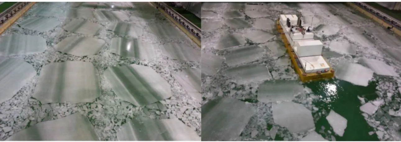
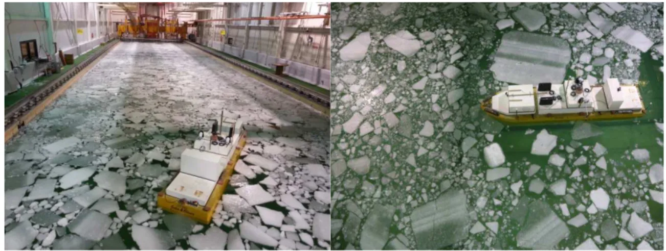
Transverse cut for small ice pieces across the tank was made by using the blades attached in the service carriage. A set of blades powered by the hydraulic system was moved down multiple times to create the small ice piece channel. Once all cuts were finished, ice floes were re-arranged as shown in the right of Figure 5. Figure 6 (left) shows the tested ice floe (100m in full scale) in the ice tank. Once 100m floe tests were done, the ice floes were cut in half as 50m and manually rearranged. After 50m floe tests, the ice floes were cut again for 25m floe tests. Once the model moved at the end the tank and came back, the ice field was rearranged manually. Figure 6 (right) and Figure 7 (left) show the 50 m ice floes and 25 m ice floes, respectively.
Figure 5: 100m Floe Cut with Brash/Small Piece Inclusion (left) and rearrangement of ice foes for test (right)
Four corners of ice floe were manually cut in order to reduce excessive interlocking between ice floes. When the ice field was rearranged, a photograph of the field condition was taken before the model tests began. For repeat tests, another photo survey was done. Because tests were primary focused on the effect of each parameters including floe size, most ice field had the same size of floes. Some tests, however, had a mixture of large, medium and small floes to increase realism. A mixed field was made by reserving some of large, medium floes during the 1st day tests and the field was rearranged for 2nd day tests (Figure 7, right).
Concentration was calculated based on the ice covered area. For the light concentration, some of the ice floes had to be removed to the non-testing area (set up area, 15m), then the rest of the field was
uniformly rearranged. Although best effort was made to match the initial concentration, it was
impossible to keep the same concentration over the entire tests. Multiple camera systems were used to identify instantaneous concentration in the near field as well as far field. The term of “nominal
concentration” or just “concentration” indicates the initial concentration for the present test program.
Figure 7: 25m ice floe field (left) and mix size field (right)
2.3.1 Ridge fragment
Some tests included ridge fragments in the 25m ice floes field. Figure 8 (left) shows the ridge fragments in the black container, which was manufactured in the cold room with blocks of ice, and their
deployment from the service carriage. Ridge fragments were deployed every 5 m along the centre of the tank and re-froze overnight. Next morning, test staff broke any consolidate layer and rearranged the field. Figure 8 (right) shows a representative ridge fragment interaction with the hull in 25m ice floes.
Figure 8: Ridge fragment deployment (left) and test (right)
2.3.2 Level ice and 1st year ridge penetration
A number of tests were carried out in level ice. Level ice at 0.6m thick with a flexural strength of approximately 700 kPa was prepared and tested as shown in Figure 9 (left). Due to the steep bow angle (60° to model baseline), most failure mode during level ice tests was crushing. For the given ice
thickness, the model was able to move at target speeds (or stationkeeping with the main carriage that moved at target speeds). Over the course of the run, slight change of the yaw angle made a progressing yaw error since the yaw angle couldn’t be corrected due to the compaction of the ice around the model. First year ridge was also built and ridge penetration tests were carried out as shown in Figure 9 (right).
Figure 9: Level ice tests (left) and first year ridge penetration tests (right)
3.0 Experiments
In the current test program a total of seventeen ice sheets were generated and tested. The test program lasted for nearly two months. Multiple ice configurations were prepared and tested in these ice sheets to evaluate the effect of ice floe size, floe thickness, ice drift speed and direction. The detailed test
variables for managed ice are provided in Table 1 below. In addition, level ice, ridge penetration and ridge fragment tests were performed.
Three model’s initial conditions were studied in the current test program, namely, the forward ice tests, the weather vanning tests and the oblique ice tests. In the forward ice testing, both the vessel yaw set point and initial heading were set to 0°for the entire test length. In the weather vanning tests, the vessel yaw set point was set to 0° but the initial heading of the vessel was set to a non-zero value (varied from ±5° to ±30°). In the oblique ice testing, the yaw set point was set for a non-zero value (varied from ±5° to 90°). Some of the oblique ice tests were completed by changing the yaw set point in steps, e.g. 10° to 0° to -10°, for a single test run. In other oblique tests, an oblique angle e.g. 10° was maintained for the entire test run.
Table 1: Test variables for managed ice
For each of the tests in managed ice, the DP system of the vessel was set to track and maintain pre-determined position and heading set points relative to the main carriage in the ice tank. Ice drift was simulated by allowing the vessel to move through a stationary ice field while following the set point fixed on the main carriage moving through the ice tank. For some of the heavy ice conditions, the whole thrust controlled by DP system was insufficient to maintain/follow the target set point. In such cases, the
model was operated in semi DP mode or fully manual mode. The present paper does not include any analysis of the data obtained from such tests. The linear and angular motions of the vessel were measured using the Qualysis® motion capture system. In addition to the motions, the linear
accelerations and rotational rates were also measured. Changes in the ice drift angle were simulated by changing the heading of the vessel through the DP control interface. Note that only the initial heading of the vessel was controlled.
All DP tests in managed ice were run along the basin length in multiple segments. Tests were completed with each test section having different advance speeds. A total of three test runs with different advance speeds were completed within one start to end length of the basin. For each of the managed channel experiments in ice, the model was run into the ice for at least four (4) model lengths (at least 20m in the basin). This was to make sure sufficient data wass obtained for hull-ice interactions. The ITTC
guidelines (2011) suggest a minimum test length of two (2) model lengths to achieve a steady-state data signal. In managed ice condition, however, this may result in too few interactions with individual floes, especially at low concentrations. After the third speed was completed, the model was brought back to the starting position in the tank. And then the repeat tests were carried out. After repeat runs, the
remaining ice pieces in the tank were then broken into the second floe size (50m) and distributed evenly in the tank to obtain the same concentration. The model was then driven through the ice sheet in the three speeds and runs repeated. The ice was broken again to simulate third floe size (25m) and the test was continued.
Data collection was started with the model at rest before the experiment and stopped when model was at rest, after the experiment. Time histories were plotted for inspection of each data channel as quickly as possible. During the detailed data analysis, the mean values from the stationary period were used as a tare value.
4.0 Data Analysis
4.1 Global Forces and Moments
The global forces and moments for the model were estimated from the thrusts of individual pod unit by resolving them in the desired directions and by considering the relative locations of each pod unit relative to the global center (vessel CG).
��� (�����) = �� sin(��); ��� (����) = ����� (��) ������ ����� ����� = � ��� 6 �=1 ������ ���� ����� = � ��� 6 �=1 ������ ��� ������ = � ��� × ��� + � ��� × ��� 6 �=1 6 �=1
Where, Fxi is the surge force (longitudinal force) for the “ith” thruster, Fyi is the sway force (side force) for the “ith”thruster, θ is the azimuthing angle, �� and �� is the moment arm (distances from CG to the thruster in the y (transverse) and x (longitudinal) direction, respectively).
4.2 Test Segments
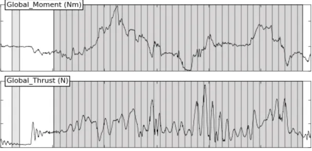
For the data analysis, the data was split into multiple time segments each representing a different ice-ice and ice-structure interaction event. It was assumed that ice interaction events changed every 20m in full
scale. The length of each time segment was then determined based on a predetermined ice-hull interaction interval of 20 m and the vessel speeds. These individual time segments were used for
statistical analysis shown below. For all DP in ice experiments, the first time segment was selected from the time when the model bow completely entered the managed ice and the last time segment was
selected cautiously to avoid any tank wall effect. Figure 10 shows the example time series of global thrust and moment. For this run, total 40 segmented events were analyzed.
4.3 Basic Statistical Analysis
The basic statistics (mean, maximum, minimum and standard deviation) were calculated for each data signal on all segments. Since there were discrete sizes/numbers of ice floes interacting with the model hull, one run was considered as a collection of the discrete events in every 20 m in full scale as
explained earlier. Once the discrete events were selected the following parameters were analyzed in the preliminary stage:
• Surge (m) vs. surge force (N) • Sway (m) vs. sway force (N)
• Yaw angle (deg) vs. yaw moment (Nm).
It was expected that the slopes of those graphs were strongly dependent on the gain set up for the DP system. Once satisfied with the correlation expected from the above analysis, further in-depth analysis was carried out to evaluate the effects of each ice parameter on the global forces and moments
encountered by the hull due to hull-ice interactions. Another important outcome from this analysis was a load distribution for each motion, as well as probability analysis to evaluate the operational envelope based on the extreme probability. Further discussion is addressed in section 5.2.
Figure 10: Multiple (40) segmented events for data analysis
4.4 Video analysis
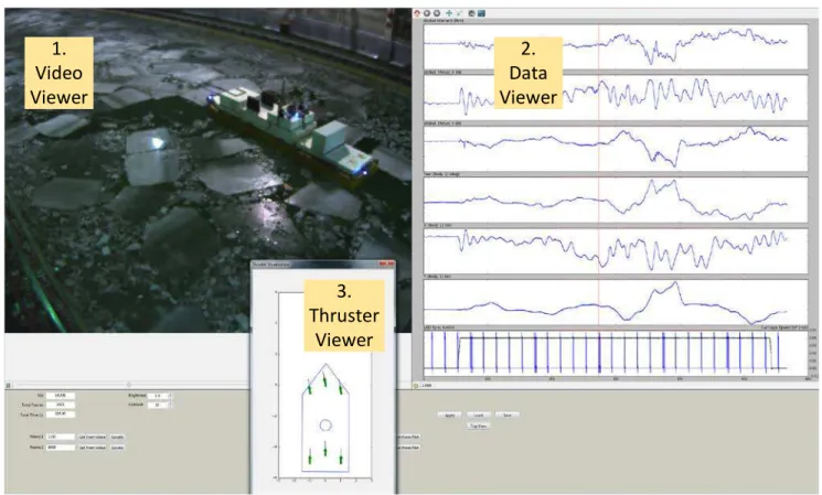
Video analysis for this type of testing is very important because ice condition is always changing. From the video analysis, a number of interactive ice floes, ice interaction behavior and its failures were carefully assessed. Those observations were correlated with global load and motion. For this purpose, NRC developed a video analysis tool shown in Figure 11. The figure shows the video / data / thruster viewer used for the analysis. Left top (section 1) shows the video and right top (section 2) shows the synchronized time series data. In the data viewer, from the top to bottom, the channels are global MZ
(yaw moment), FX (surge force), FY (sway force), yaw, surge, sway motions and carriage speed with
sync pulse. Bottom (section 3) shows the thruster viewer where a full green arrow represents full power of the thruster. It also shows the instantaneous heading of the vessel.
Figure 11: Video / Data / Thruster viewer for video analysis.
4.4.1 Ice-Structure Interaction Scenarios
The analyses of the physical ice-vessel interaction processes observed during the tests indicated that the DP stationkeeping of a vessel in managed ice involved complex ice behavior with multiple physical processes that were non-linearly interlinked contributing to the ice-hull interactions. Ice-Ice interactions in both near and far field were needed to be evaluated in order to assess the ice loads on the vessel. The interaction events included breaking, splitting, sliding, rotating, jamming and interlocking. The existence of brash ice played a major role in “damping effect” between ice pieces and encouraged smooth
transition of ice loads when the ice pieces were interacting with each other. Ice-Ice interactions in the near field were more dynamic due to proximity of presence of a moving vessel and propeller wake. In the far field, the interactions were relatively less dynamic; more jamming and interlocking events were observed rather than breaking, splitting, rotating or sliding events.
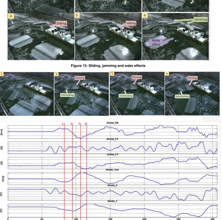
Figure 12 shows various types of ice interaction. When the ice floe was off the centre of the model, sliding and rotating events were dominant. Due to high concentration, ice jamming events were also observed in both near and far field. Due to jamming/tank wall effects on the starboard side, the DP system of the model tried to correct yaw/sway (slightly off to the port side- try to move to the starboard side) and propeller wake made an ice free area on the port side. For the medium/small ice floes with light concentration, the effect of the propeller wake was significant.
Figure 13 shows rotating and interlocking events and corresponding loads and motions. Ice floe was located in the bow of the starboard side and it started to rotate by the model. The x force (Global_FX, surge force) wasn’t significant since rotating from one corner wouldn’t require high force. During the
1. Video Viewer 2. Data Viewer 3. Thruster Viewer
contact, the floe rotated, interlocking with an adjacent floe and with that, the yaw angle (Model_Yaw) and the yaw moment (Global_MZ) changed greatly. The wall effect might contribute the model’s behavior as well since the second ice floe was close to the wall.
Figure 12: Sliding, jamming and wake effects
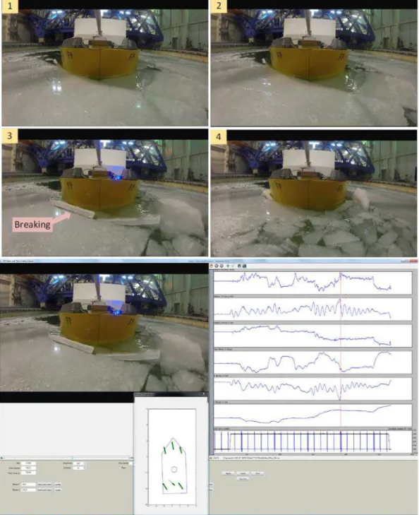
4.4.2 Ice Floe Failure Modes
Different from the level ice condition (as described in 2.3.2), the large ice floes tended to be broken by flexural bending process because crushing events required a lot more constraint. Ice floes were pushed by the vessel relatively freely and when the floe was constrained due to interacted ice pieces, it was slightly tilted and broken due to bending. Figure 14 shows an example event for ice floe breaking and hull loads and motions when the breaking happened. When the ice piece was broken, surge motion rapidly increased and the thrusters responded to reduce rps and/or to rotate azimuth angle in opposite direction, which can be seen as a sudden decrease in Fx (See Figure 14 (right) data viewer- second from the top; channel names of the viewer was addressed in 4.4).
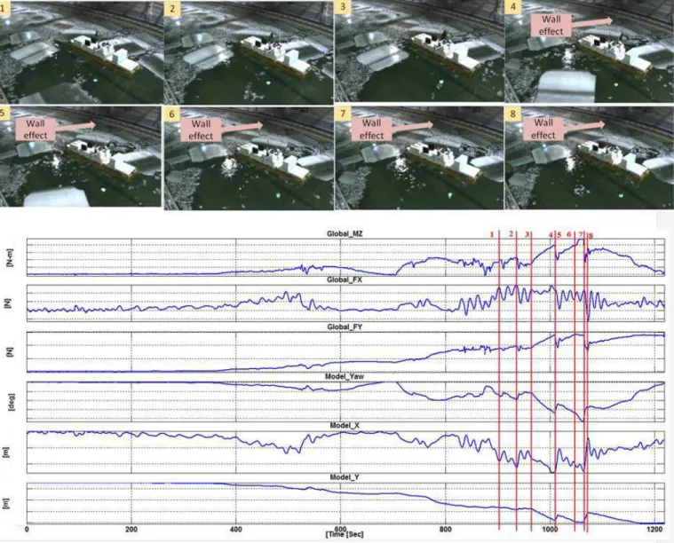
4.4.3 Ice Tank Wall Effects
It has been found during some of the tests that the ice basin walls imposed boundary conditions on the entire domain of the physical ice-vessel system. During the analysis of the data and the video, it is noted that the ice-hull interaction processes depend heavily on the boundary conditions of the physical domain and the compaction effects produced by the walls of the basin, particularly for higher ice concentration or bigger ice floes. Figure 15 shows an example of boundary effect and corresponding vessel load and motions. High loads/large offsets were observed when several 100 m floes were interlocked or
compacted and the side wall restricted for ice pieces to move anywhere. The compacted ice regime caused a large yaw angle /sway and the model tried to correct the angle by yaw/sway motion, which was nearly impossible due to the side wall.
Figure 15: Video image and corresponding hull loads showing side wall effect
5.0 Test results
A summary of the hull forces and moments in the horizontal plane in 7/10th managed ice configurations in the forward ice tests is given in Figure 16. In this figure, DP in the legends means fully DP controlled vessel and RF means the ice field had ridge fragments included. The figure shows the offset distance
from the set point versus the corresponding surge and sway loads and global moment. RF plots show more centralized (offset from set point was near to zero) than regular DP conditions simply because of lack of runs. Sometimes ridge fragments weren’t hit by the vessel. The figure shows that once the DP mode is engaged there is a strong linear trend suggesting the linearity in the proportional gain in the DP system.
Figure 16: Surge, sway forces and global moment versus offset for all tests with 7/10th ice concentration
5.1 Probability Analysis
The discrete data points for a number of managed ice tests in similar ice conditions are fitting through a number of distribution and the PDF parameters for the best fit(s) are estimated using a number of goodness of fit tests. Once the parameters are estimated, the CDF can be plotted in an appropriate graph to obtain the probability of non-exceedance of various loads for a desired return period in order to provide statistically valid deterministic ice loads, see Figure 17. It is noted that the extreme probability analysis is not shown here. This analysis of ice loads is expected to provide more detailed operational envelope for DP in ice.
5.2 Performance of the DP Controlled Hull in Managed Ice
Figure 18 shows a preliminary operational envelope of the tested DP model. In the figure, the manual control means that the model couldn’t keep the position using a DP mode due to heavy ice condition so that the operator controlled the model manually. Normally the manual control used the maximum power to move the model to a desired area. Partly manual control means the model could be operated by a DP mode for most cases but there are a few cases to use a manual control. It is noted that among the green circles in the figure, some of the operations are much easier than the others. The results presented in the figure should be considered qualitative.
Figure 18: Operational envelope of the DP model
6.0 Conclusions
This paper describes a summary of the model test for a dynamic positioning vessel in managed ice in the National Research Council’s (NRC) ice tank. A total of 372 runs were carried out using 17 ice sheets. Test variables included floe size, floe thickness, inclusion of brash ice and small ice pieces, ice drift speed and direction. The run length at each speed was about four ship lengths.
The tests were designed to simulate realistic Arctic ice conditions or scenarios. The mixture of brash ice and small ice pieces maximized the reality and their contribution seemed appropriate. Brash ice and small ice pieces acted as a damper and provided a space for the floes to move around. It also reduced the rapid motion when ice floes were bouncing off and/or sliding against each other. With a given scale ratio, four 100m floes were made across the tank. It would be the minimum number that the vessel was able to move through at the light concentration. For the heavy concentration, multiple 100m floes were compacting and the vessel was not easily operable. In most100m floe ice tests, the initial position of the vessel was always between ice floes. For 50m and 25m floe, the vessel didn’t have many challenges regardless of the initial position.
Data analysis was conducted by creating discrete events from each continuous time traces by using uniform time segment selections. The reason for using discrete events is to investigate the instantaneous ice loads and corresponding DP’s response. In addition, the randomness of the field condition makes the proper prediction of the ice loads difficult. In the data analysis it was assumed that the ice interaction condition changed in every 20m in full scale. Therefore all test data were divided into 20m segments and analyzed. Based on the given data analysis method, the results showed the good agreement between the proportional gains for surge, sway and yaw from DP system and the slope from the graphs of surge
force/surge, sway force/sway, and yaw moment/yaw, respectively. Once the model is in DP mode, the vessel behavior should be guided based on the gain values. The ice load distributions in a format of PDF (probability density function) at a certain test condition (incorporated with video data), which is
obtained from the above data analysis, were an essential data product to understand the characteristics of the DP vessel’s response in the given managed ice field.
Some analysis has been carried out to evaluate the effect of different managed ice parameters on the global loads and moments of the model hull for all forward ice tests. Based on the analysis, it was concluded that with the increase in the drift speed, there was an increase in the surge load, for the
constant ice concentration, the floe size and the ice thickness. The surge load increased with the increase in the floe size. Similar to the floe size effect, the surge load increased with the increase in the ice thickness.
An NRC developed DP algorithm was used and satisfactory behavior was observed. Wake effect from the thrusters seemed significant in terms of dispersion of ice pieces, which was not accounted for in the current DP system. The experience in the current DP system in stationkeeping in managed ice condition warrants improvement in the DP algorithm to account for the instantaneous ice field parameters, ice-thruster wake interactions and hull-ice-thruster interactions. Sway motion could also be improved. Instead of pure sway motion which requires huge thrust and is nearly impossible to move due to the wide contact area, the vessel should be able to move around within a given watch circle. Another area may be a vision system. Camera system with a proper ice load prediction model enables us to predict the near future ice interaction events and the DP system starts responding before the events actually occur, which can reduce rapid action of thrusters and maximize the operational envelope.
7.0 Acknowledgements
On behalf of the technical team at OCRE-NRC, the authors thank the Centre for Marine Simulations of the Fisheries and Marine Institute (CMS-MI) of Memorial Univeristy, Petroleum Research of
Newfoundland and Labrador (PRNL), Atlantic Canada Opportunities Agency (ACOA), and Research Development Corporation (RDC), and Kongsberg Digital Simulation Ltd (KDS) for their financial supports. Thanks are also extended to all OCRE-NRC technical services staff for their work during model test phase I program. The Marine Vehicle program of OCRE-NRC portfolio is acknowledged for its support in drafting this article. Last but not least, the authors would like to acknowledge all affiliated companies for allowance to publish this paper.
8.0 References
Gash, R. and Millan, J. 2012. Managed Ice Loads on a Dynamically Positioned Vessel. In Proc. of the Arctic Technology Conference. Hals, T., and Efraimsson, F. 2011. DP Ice Model Test of Arctic Drillship. In Proc. of the Dynamic Positioning Conference.
Hamilton, J., Holub, C., Blunt, J., Mitchell, D., Kokkinis, T. 2011. Ice Management for Support of Arctic Floating Operations, In Proc. of the Arctic Technology Conference.
Islam, S., Wang, J., Mills, J., Sayeed, T., Gash, B., Lau, M., Millan, D. and Millan, J. 2016. DP in Ice Environment – Improving Safety and Efficiency of Arctic Operations. In Proc. of the Arctic Technology Conference.
ITTC. 2011. International Towing Tank Conference - Section 7.5-02-04 Ice Testing. Recommended Procedures and Guidelines. Jenssen, N. A., Hals, T., Jochmann, P., Haase, A., dal Santo, X., Kerkeni, S., Doucy, O., Gürtner, A., Støle Hetschel, S., Moslet, P. O.,
Metrikin, I., and Løset, S. 2012. DYPIC - A Multi-National R&D Project on DP Technology in Ice. In Proc. of the Dynamic Positioning Conference.
Kerkeni, S., Dal Santo, X., Doucy, O., Jochmann, P., Haase, A., Metrikin, I., Loset, S., Jenssen, N., Hals, T., Gurtner, A., Moslet, P., and Støle-Hentschel, S. 2014. DYPIC Project: Technological and Scientific Progress Opening New Perspectives. Offshore Technology Conference. doi:10.4043/24652-MS.
Kjerstad, O. K., Metrikin, I., Loset, S., and Skjetne, R. 2014. Experimental and Phenomenological Investigation of Dynamic Positioning in Managed Ice. Cold Regions Science and Technology. doi: 10.1016/j.coldregions.2014.11.015.