Publisher’s version / Version de l'éditeur:
Vous avez des questions? Nous pouvons vous aider. Pour communiquer directement avec un auteur, consultez la première page de la revue dans laquelle son article a été publié afin de trouver ses coordonnées. Si vous n’arrivez Questions? Contact the NRC Publications Archive team at
PublicationsArchive-ArchivesPublications@nrc-cnrc.gc.ca. If you wish to email the authors directly, please see the first page of the publication for their contact information.
https://publications-cnrc.canada.ca/fra/droits
L’accès à ce site Web et l’utilisation de son contenu sont assujettis aux conditions présentées dans le site LISEZ CES CONDITIONS ATTENTIVEMENT AVANT D’UTILISER CE SITE WEB.
Client Report (National Research Council of Canada. Construction), 2018-08-08
READ THESE TERMS AND CONDITIONS CAREFULLY BEFORE USING THIS WEBSITE.
https://nrc-publications.canada.ca/eng/copyright
NRC Publications Archive Record / Notice des Archives des publications du CNRC :
https://nrc-publications.canada.ca/eng/view/object/?id=f444b1ba-c6f5-49fd-8bd1-d8269c3717cf https://publications-cnrc.canada.ca/fra/voir/objet/?id=f444b1ba-c6f5-49fd-8bd1-d8269c3717cf
NRC Publications Archive
Archives des publications du CNRC
For the publisher’s version, please access the DOI link below./ Pour consulter la version de l’éditeur, utilisez le lien DOI ci-dessous.
https://doi.org/10.4224/23004642
Access and use of this website and the material on it are subject to the Terms and Conditions set forth at
Fire testing of rooms with exposed wood surfaces in encapsulated
mass timber construction
Su, Joseph; Leroux, Patrice; Lafrance, Pier-Simon; Berzins, Rob; Gratton,
Karl; Gibbs, Eric; Weinfurter, Mark
FIRE TESTING OF ROOMS WITH
EXPOSED WOOD SURFACES IN
ENCAPSULATED MASS TIMBER
CONSTRUCTION
Joseph Su, Patrice Leroux, Pier-Simon Lafrance, Rob
Berzins, Karl Gratton, Eric Gibbs, Mark Weinfurter
8 August 2018
Fire Testing of Rooms with Exposed
Wood Surfaces in Encapsulated Mass
Timber Construction
Lead Author
Joseph Su, PhD
Approved
Philip Rizcallah, P. Eng.
Program Director – Building Regulation for Market Access NRC Construction Research Centre
Report No: A1-012710.1 Report Date: 8 August 2018 Contract No: A1-012710
Agreement date: 27 October 2017 (NRCan)
22 November 2017 (Province of Ontario)
72 pages
Copy no. 1 of 7 copies
This report may not be reproduced in whole or in part without the written consent of the National Research Council Canada and the Client.
Table of Contents
List of Figures ... iii
List of Tables ...v
Executive Summary ...vi
1. INTRODUCTION...1
2. TEST SETUP AND PROCEDURE...1
2.1 Test Matrix ...1
2.1.1 CLT enclosure of test rooms...2
2.1.2 Glulam beams and columns in test rooms ...7
2.1.3 Ventilation opening ...8
2.1.4 Encapsulation materials...8
2.2 Moisture Content...9
2.3 Fire Load and Ignition Scenario...10
2.4 Instrumentation and Measurements ...10
2.4.1 Room temperatures...14
2.4.2 Temperatures inside CLT panels and at gypsum board interfaces...14
2.4.3 Char measurements ...16
2.5 Test Procedure ...16
3. RESULTS AND DISCUSSIONS...17
3.1 Test 1...18
3.1.1 Room temperatures...20
3.1.2 Temperatures at gypsum board interfaces and inside CLT panels...20
3.2 Test 2...25
3.2.1 Room temperatures...27
3.2.2 Temperatures at gypsum board interfaces and inside CLT panels...27
3.2.3 Char of CLT panels...31
3.3 Test 3...33
3.3.1 Room temperatures...33
3.3.2 Temperatures at gypsum board interfaces and inside CLT panels...35
3.3.3 Char of Glulam beams and columns as well as CLT panels ...39
3.4 Test 4...43
3.4.1 Room temperatures...45
3.4.2 Temperatures at gypsum board interfaces and inside CLT panels...45
3.4.3 Char of Glulam beam and column as well as CLT panels...49
3.5 Test 5...53
3.5.2 Temperatures at gypsum board interfaces and inside CLT panels...55
3.5.3 Char of CLT panels...60
4. CONCLUSIONS...62
ACKNOWLEDGMENTS...64
List of Figures
Figure 1. Room schematic for Test 1 – fully encapsulated. ...3
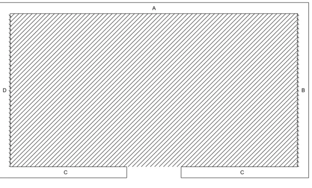
Figure 2. Room schematic for Test 2 – Wall A and 10% ceiling exposed. ...3
Figure 3. Room schematic for Test 3 – fully exposed columns and beams. ...4
Figure 4. Room schematic for Test 4 – fully exposed ceiling, column and beam. ...4
Figure 5. Room schematic for Test 5 – fully exposed ceiling, Wall B and Wall D...5
Figure 6. Details of CLT panel connections...5
Figure 7. Photographs of test room construction. ...6
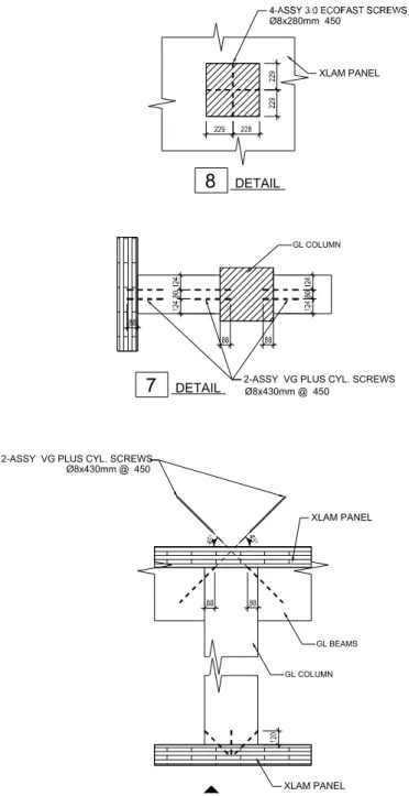
Figure 8. Connection details of Glulam beams and columns and CLT panels. ...7
Figure 9. Stair-step installation for multilayer gypsum board. ...9
Figure 10. Photographs of (a) wood cribs and (b) middle crib ignition. ...10
Figure 11. Thermocouple trees and embedded thermocouple groups in Test 1. ...11
Figure 12. Thermocouple trees and embedded thermocouple groups in Test 2. ...11
Figure 13. Thermocouple trees and embedded thermocouple groups in Test 3. ...12
Figure 14. Thermocouple trees and embedded thermocouple groups in Test 4. ...12
Figure 15. Thermocouple trees and embedded thermocouple groups in Test 5. ...13
Figure 16. Heights of thermocouples on the thermocouple trees in test rooms...13
Figure 17. One of the thermocouple groups embedded in the test structure ...14
Figure 18. A group of embedded thermocouples...15
Figure 19. CLT room during and after Test 1...19
Figure 20. Room temperatures during Test 1...20
Figure 21. Temperatures in CLT and at gypsum interfaces for ceiling assembly in Test 1...21
Figure 22. Temperatures in CLT and at gypsum interfaces for Wall A in Test 1. ...22
Figure 23. Temperatures in CLT and at gypsum interfaces for Walls B, C and D in Test 1...23
Figure 24. CLT room with Wall A and 10% ceiling exposed for Test 2...25
Figure 25. Photographs of the CLT room during Test 2...26
Figure 26. Room temperatures during Test 2...27
Figure 27. Temperatures in CLT Wall A in Test 2...28
Figure 28. Temperatures in CLT and at gypsum interfaces for ceiling assembly in Test 2...29
Figure 29. Temperatures in CLT and at gypsum interfaces for Walls B, C and D in Test 2...30
Figure 30. CLT char depth versus time in Test 2...31
Figure 31. A Resistograph drill used to determine CLT char depth after Test 2...32
Figure 32. Mass timber room with fully exposed beams and columns for Test 3. ...33
Figure 33. Exposed beams and columns in the fire room during Test 3. ...34
Figure 34. Room temperatures during Test 3...35
Figure 35. Temperatures in CLT and at gypsum interfaces for ceiling in Test 3. ...37
Figure 36. Temperatures in CLT and at gypsum interfaces for Wall A in Test 3. ...38
Figure 37. Temperatures at CLT and gypsum interfaces for Walls B, C and D in Test 3. ...39
Figure 38. Photograph of mass timber elements after Test 3. ...40
Figure 39. Sampling for remaining depth of Glulam beam and columns after Test 3. ...41
Figure 40. CLT char depth versus time in Test 3...42
Figure 41. Mass timber room with exposed CLT ceiling, Glulam beam and column for Test 4. .43 Figure 42. Exposed ceiling, beam and column in mass timber room during Test 4. ...44
Figure 43. Room temperatures during Test 4...45
Figure 44. Temperatures in CLT ceiling panels in Test 4. ...47
Figure 45. Temperatures in CLT and at gypsum interfaces for Wall A in Test 4. ...48
Figure 46. Temperatures in CLT and at gypsum interfaces for Walls B, C and D in Test 4...49
Figure 48. Sampling for remaining depth of Glulam beam and column after Test 4...51
Figure 49. CLT char depth versus time in Test 4...52
Figure 50. CLT room with fully exposed ceiling, Wall B and Wall D for Test 5...53
Figure 51. CLT room during Test 5. ...54
Figure 52. Room temperatures during Test 5...55
Figure 53. Temperatures in CLT ceiling panels in Test 5. ...57
Figure 54. Temperatures in CLT and at gypsum interfaces for Wall A in Test 5. ...58
Figure 55. Temperatures in CLT and at gypsum interfaces for Walls B, C and D in Test 5...59
List of Tables
Table 1. Matrix of mass timber room fire tests...2
Table 2. Type X gypsum board and screws used for CLT encapsulation. ...8
Table 3. Average moisture content of mass timber elements. ...9
Table 4. Mass timber room components and fire test results (February and March 2018)...17
Table 5. Time to reach 300°C at gypsum board interfaces and inside CLT in Test 1...24
Table 6. Time to reach 300°C at gypsum board interfaces and inside CLT in Test 2...30
Table 7. Total char depth of CLT panels in Test 2...32
Table 8. Time to reach 300°C at gypsum board interfaces and inside CLT in Test 3...36
Table 9. Total char depth of CLT panels in Test 3...41
Table 10. Time to reach 300°C at gypsum board interfaces and inside CLT in Test 4...46
Table 11. Total char depth of CLT panels in Test 4...51
Table 12. Time to reach 300°C at gypsum board interfaces and inside CLT in Test 5...56
Table 13. Total char depth of CLT panels in Test 5...61
Executive Summary
In early 2018, with funding support from Natural Resources Canada and the Province of Ontario, the National Research Council Canada conducted a series of room scale fire tests of
Encapsulated Mass Timber Construction (EMTC). The goal of this test series is to further
quantify the contribution of mass timber elements to fires and provide additional data for forming the technical basis for exposed mass timber elements in EMTC buildings without significantly increasing fire risks to life and property. The goal includes studying the fire performance of the 2ndgeneration cross-laminated timber (CLT)1in resisting char layer fall-off, which could cause
fire regrowth in the cooling phase of fully developed fires. The issues of char layer fall-off for the 1stgeneration CLT panels resulting in fire regrowth during the cooling phase of the fire were
clearly revealed in the previous large scale CLT compartment fire tests under the auspices of the Fire Protection Research Foundation.
Five room fire tests were conducted, incorporating mass timber structural elements of Glulam beams and columns and second generation CLT panels. The second generation CLT panels were manufactured using nominal 2 x 4 (38 mm x 89 mm) spruce-pine-fir lumber glued with a new thermal resistive polyurethane adhesive (with a brand name of HBX2). The test rooms were
4.5 m long x 2.4 m wide x 2.7 m high, constructed using 175-mm thick 5-ply CLT structural panels. Each test room had a rough opening of 0.76 m wide x 2.0 m high with a ventilation factor of 0.03 m½. The CLT surfaces in the test rooms were fully or partially covered using
multiple layers of Type X gypsum board. Two of the test rooms incorporated Glulam beams and columns. The Glulam cross sections were 327 mm x 457 mm for beams and 457 mm x 457 mm for columns, respectively. The columns were fully exposed from the four sides. The beams were fully exposed from the three sides, with the CLT ceiling assembly covering the top side of the beams. Wood cribs were used to simulate residential room contents with a fire load density of 550 MJ/m2in the room. The fire tests were conducted without sprinklers in order to achieve the
goal of the tests.
In general, this series of mass timber room fire tests utilized more challenging test conditions than the previous large scale CLT compartment fire tests conducted under the auspices of the Fire Protection Research Foundation (FPRF) [1]. In this series of mass timber room tests,
1. Greater surface area (as a % of total surface area) of exposed timber was used; 2. Less layers of encapsulation (noncombustible fire protection) were used to protect the
CLT elements – two layers of 12.7 mm thick Type X gypsum board (instead of three layers of 15.9 mm thick Type X gypsum board);
3. The ventilation factor was the same as the FPRF smaller opening size resulting in a greater fire severity, leading to a more significant fire impact on the mass timber elements; and
4. The same fire load density was used.
All tests in this series showed that the second generation CLT with the thermal resistant
adhesive improved significantly in fire performance to resist the char layer fall-off. There was no char layer fall-off long after the char front had passed the glue bond line in this test series. The
1Refers to CLT products with thermal resistant adhesives that are compliant with ANSI/APA
PRG-320:2018.
2Certain commercial products are identified in this report to specify the materials used and the
procedures employed. In no case does such identification imply endorsement or recommendation by the National Research Council Canada, nor does it indicate that the products are necessarily the best available for the purpose.
char rate decreased with the increasing char depth to the CLT as the char formed a thermal barrier to heat transfer. For the exposed (unprotected) CLT panels, the char rate was initially in a range of 0.6-1.0 mm/min and then decreased as the char front moved inward through the CLT. For the gypsum-board protected CLT panels, the char rate was less than 0.20 mm/min after the time when the CLT began to char behind the gypsum board.
In all tests with exposed mass timber, the peak room temperatures were similar to the baseline (fully encapsulated) but the fully developed fire stages were longer than the baseline as the exposed timber added more fuel load to the rooms. In three of the tests (Tests 1 (baseline), 2 and 4), the fire eventually burned-out leading to self-extinguishment.
The results of Test 2 and Test 4 indicate that, under the experimental conditions used in these tests, the current limits described in proposed Article 3.1.18.4 for the National Building Code of Canada (NBCC) (2020) to permit some exposed mass timber in EMTC construction would be unlikely to increase the fire risks significantly to life and property. The following table lists different scenarios of exposed mass timber surface(s) to be permitted by the proposed Article 3.1.18.4; these scenarios have been demonstrated by Test 2 and Test 4 to be unlikely to cause a significant increase of fire risk.
Test Verification of the Proposed Limits for Exposed Surfaces in EMTC.
Permitted Code-Prescribed Scenarios for Exposed
Surface(s)
Limit of Proposed NBCC (2020) Article
3.1.18.4 Verified by Tests in This Report
1 Wall(s) only
(facing one direction) 35% of total suite perimeter wall area
Test 2
One long wall fully exposed (= 33% of perimeter wall area)
+ 10% ceiling exposed 2
Wall(s) (facing one direction)
+
Ceiling (FSR ≤ 150)
Wall(s) at 35% total suite perimeter wall area + ceiling at 10% total suite ceiling area
3 Ceiling only 10% of total suite ceiling area if FSR ≤ 150 or
25% of total suite ceiling area if FSR ≤ 75
Test 4
Beam/column fully exposed (= 19% of perimeter wall area)
+ 100% ceiling exposed 4 Beams/columns/arches only 10% of total suite or fire compartment perimeter wall area
5
Beams/columns/arches +
Ceiling (FSR ≤ 150)
B/C/A at 10% of total suite or fire
compartment perimeter wall area + ceiling at 10% of total suite ceiling area
6
Beams/columns/arches +
Ceiling (FSR ≤ 75)
B/C/A at 10% of total suite or fire
compartment perimeter wall area + ceiling at 25% of total suite ceiling area
Scenarios 1, 2 and 3 for limits of exposed wall and/or ceiling surface(s) are demonstrated by Test 2. Scenarios 3, 4, 5 and 6 for limits of exposed beam-column-arch and/or ceiling surface(s) are demonstrated by Test 4. It is worthwhile to note that Test 4 used much more exposed mass timber surfaces than the proposed limits, yet the fire burned-out and self-extinguished; the Glulam char rate was in a range of 0.26 to 0.38 mm/min for each exposed side of the beam and column in four hours.
Fully exposed beams and columns, equal to 36% of the total perimeter wall area, were used in Test 3. The fire reached the decay phase. The Glulam char rate was in a range of 0.38 to 0.67 mm/min for each exposed side of the beams and columns in four hours.
A fully exposed ceiling (100%) and two fully exposed opposing walls (35% perimeter wall area) were used in Test 5, which are in excess of the proposed limits for NBCC and the International Building Code. The room fire reached a fully developed phase, followed by a fire decay phase. During this decay phase, flaming combustion on the exposed CLT surfaces ceased at around 100 min as the char layer insulated the CLT. The char remained on the exposed CLT surfaces long after the char front had passed the first glue-bond line. Meanwhile, the CLT wall panels protected by gypsum board started to produce constant small flames coming through the gypsum board cracks and vertical junctions from 60 min to 220 min. These small flames started to re-ignite the bottom portion of the already-charred exposed opposing CLT walls at 220 min, which gradually moved upward to spread over the exposed CLT wall and ceiling surfaces in the room at 230 min.
This series of five room scale fire tests provide new data for quantifying the contribution of mass timber elements to fires and for forming the technical basis for the allowance of some amount(s) of exposed mass timber in the EMTC buildings.
Fire Testing of Rooms with Exposed Wood Surfaces
in Encapsulated Mass Timber Construction
Joseph Su, Patrice Leroux, Pier-Simon Lafrance, Rob Berzins, Karl Gratton, Eric Gibbs, Mark Weinfurter
Fire Safety, National Research Council of Canada
1. INTRODUCTION
The National Building Code of Canada (NBCC) is revised every five years. Proposed Change Forms (PCFs) have been developed and approved in principle to introduce a new type of construction, Encapsulated Mass Timber Construction (EMTC), to the NBCC 2020. The
proposed EMTC provisions would permit some exposed mass timber under specific conditions. Although some test data on exposed cross-laminated timber (CLT) in compartment fires were available [1, 2, 3], there were still gaps in technical data to form the basis for establishing the maximum amount of exposed mass timber to be allowed in the EMTC buildings. The CLT compartment fire tests in reference [1] showed char layer fall-off behaviour of exposed CLT due to the use of a low melting-point adhesive in CLT production, which resulted in fire regrowth in the decay phase of the fully developed fire. This demonstrates a need in some fire scenarios for heat resistive adhesives to be used in CLT to resist char layer fall-off. Further study is
necessary to test the CLT products with heat resistive adhesives which do not exhibit the char layer fall-off (referred to as the second generation CLT hereafter3). In addition, there is a lack of
fire performance data for EMTC structures incorporating different types of mass timber elements, such as beams and columns.
With financial support from the Province of Ontario and Natural Resources Canada, the National Research Council Canada conducted a new series of room fire tests to help fill the knowledge gaps. The room fire tests incorporated mass timber structural elements of beams, columns and second generation CLT panels. The objective of this test series is to further quantify the
contribution of mass timber elements to room/compartment fires and the surface area of mass timber that could be exposed in EMTC buildings without significantly increasing the fire risks to life and property. In order to achieve the project objective, the mass timber room fire tests were conducted without using sprinklers. (Note that the NBCC requires that all buildings taller than six storeys be fully sprinklered in accordance with NFPA 13 [4]. Recent fire tests, conducted by US Department of Agriculture’s Forest Products Laboratory, demonstrated the effectiveness of sprinklers in controlling and suppressing fires in fully exposed CLT compartments [3].) This report documents the mass timber room fire tests and the results.
2. TEST SETUP AND PROCEDURE
2.1 Test Matrix
Table 1 shows a matrix of the mass timber room fire tests. The test matrix was determined in consideration of previous fire testing, combinations of CLT (walls, floor and ceiling) and Glulam (beams and columns) structural elements, and various amounts of exposed mass timber elements. Figure 1 to Figure 5 show schematics of the mass timber rooms used in the fire tests.
3Refers to CLT products with thermal resistant adhesives that are compliant with ANSI/APA
Table 1. Matrix of mass timber room fire tests.
Test
Interior Surface Area CLT Wall A 4.5 m x 2.7 m CLT Wall B 2.4 m x 2.7 m CLT Wall C 4.5 m x 2.7 m CLT Wall D 2.4 m x 2.7 m CLT Ceiling 4.5 m x 2.4 m CLT Floor 4.5 m x 2.4 m Glulam Beam 327 mm x 457 mm Glulam Column 457 mm x 457 mm 1 3GB 3GB 3GB 3GB 3GB 3GB - -2 exposed(= 33% of perimeter) 2GB 2GB 2GB 10% exposed 90% 2GB 2GB - -3 2GB 2GB 2GB 2GB 2GB 2GB exposed (4.54 m2= 11.5% of perimeter) exposed (9.62 m2= 24.5% of perimeter) 4 2GB 2GB 2GB 2GB exposed100% 2GB exposed (2.46 m2= 6.4% of perimeter) exposed (4.81 m2= 12.6% of perimeter) 5 2GB (= 17.5% of exposed perimeter) 2GB (=17.5% of exposed perimeter) 100% exposed 2GB -
-3GB: 1 layer of 15.9 mm thick Type X gypsum board + 2 layers of 12.7 mm thick Type X gypsum board 2GB: 2 layers of 12.7 mm thick Type X gypsum board
2.1.1 CLT enclosure of test rooms
CLT panels manufactured using 2x4 spruce-pine-fir lumber glued with a thermal resistive
polyurethane adhesive (with a brand name of HBX4) were used to construct the enclosure of the
test rooms. This CLT product was manufactured with an adhesive which meets the full-scale fire test requirements recently added to ANSI/APA PRG-320-2018 [5].
The test rooms were enclosed using 175-mm thick 5-ply CLT structural panels. All CLT panels were the same size (2.438 m x 2.794 m x 175 mm) and inter-changeable for use in the walls, ceiling and floor. This provided a greater flexibility for replacing damaged panels in fire tests. Each test enclosure consisted of ten CLT panels. No structural load was used other than the self-weight of the CLT ceiling assembly.
For the Wall A, Wall C, floor and ceiling assemblies, each assembly consisted of two CLT panels connected using a spline joint with strips of 12.7 mm thick plywood nailed on each panel every 300 mm. Wall B and Wall D assemblies consisted of a single CLT panel. The
perpendicular connections of the adjacent walls, walls to ceiling, and walls to floor were all butt joints with screws. Sealant was applied in all the CLT joints. Photographs of the CLT enclosure
4Certain commercial products are identified in this report to specify the materials used and the
procedures employed. In no case does such identification imply endorsement or recommendation by the National Research Council Canada, nor does it indicate that the products are necessarily the best
construction and details of the CLT panel connection are shown in Figure 6 and Figure 7. The interior dimension of the CLT enclosure was 4.53 m long x 2.44 m wide x 2.78 m high (without gypsum board lining).
Figure 1. Room schematic for Test 1 – fully encapsulated.
Figure 2. Room schematic for Test 2 – Wall A and 10% ceiling exposed.
A B D C C Exposed Surface 4572 2438 NOTE: 2743mm Height A B D C C 483 2438 Exposed Surface
Figure 3. Room schematic for Test 3 – fully exposed columns (4 sides) and beams (3 sides).
Figure 4. Room schematic for Test 4 – fully exposed ceiling, column (4 sides) and beam (3 sides). A B D C C Exposed Surface 1396 709 711 457 2240 457 711 457 327 675 A B D C C Exposed Surface 1371 457 610 327 777
Figure 5. Room schematic for Test 5 – fully exposed ceiling, Wall B and Wall D.
(a) butt joint (b) spline joint
Figure 6. Details of CLT panel connections (sealant in joints are not shown).
A B D C C Exposed Surface = = 17 5 Ø8x280 @ 300mm
ASSY 3.0 SCREW PLY WOOD
175
WIDTH OF PLYWOOD PL12.7mm Ø3x70
GALV. SPIRALED NAILS
1 ROW OF NAILS @ 300 C/C S.I.C.
(a) sealant along spline joint (d) sealant along butt joint
(b) sealant along spline joint (e) sealant along butt joint
(c) finished spline joint (f) front view of test room
2.1.2 Glulam beams and columns in test rooms
Two of the test rooms incorporated Glulam beams and columns. The laminae were made with multiple pieces of 38 mm × 38 mm lumber. The face bonding and end joints are bonded with a polyurethane adhesive (for end-joints: Ashland UX-100/WD3-A322, CCMC 13512-L; for edge and face laminations: Ashland WD3-A322/CX-47, CCMC 13591-L). The Glulam cross sections were 327 mm x 457 mm for beams and 457 mm x 457 mm for columns, respectively. The beams were connected to the sides of the columns. The connection details of the Glulam beams and columns and CLT panels are shown in Figure 8. The columns were fully exposed from the four sides. The beams were fully exposed from the three sides with the CLT ceiling assembly covering the top side of the beams.
Figure 8. Connection details of Glulam beams and columns and CLT panels.
XLAM PANEL XLAM PANEL GL BEAMS GL COLUMN Ø8x430mm @ 450 Ø8x280mm 450 XLAM PANEL GL COLUMN
2-ASSY VG PLUS CYL. SCREWS Ø8x430mm @ 450
2-ASSY VG PLUS CYL. SCREWS
DETAIL
8
DETAIL
2.1.3 Ventilation opening
A rough doorway opening was created in the center of Wall C. After wrapped with gypsum board and ceramic fibre, the finished opening size was 0.76 m wide x 2.0 m high to give a ventilation factor of 0.03 m½in this series of the tests. The ventilation factor is calculated using
/ , where Aoand Hoare the area and height of the opening and Atthe total area of the
boundary surfaces.
In the previous CLT compartment fire tests [1], the ventilation opening size varied in different tests, with a ventilation factor of 0.03 m½or 0.06 m½. Similar peak temperatures in the
compartment were observed in all tests. However, the duration of the fully developed fire stage changed with the different ventilation factor. The smaller opening (0.03 m½ventilation factor)
resulted in a longer fully developed fire stage, creating a more severe fire exposure to the mass timber elements inside the compartment. The same ventilation factor of 0.03 m½was used for
this series of the room tests.
2.1.4 Encapsulation materials
The interior CLT surfaces were fully or partially encapsulated using multiple layers of Type X gypsum board on the walls and ceiling according to the test matrix (Table 1). Table 2 shows details of the gypsum board and screws used in each test.
Table 2. Type X gypsum board and screws used for CLT encapsulation.
Gypsum board
Test 1 (Baseline) Tests 2, 3, 4 and 5 Gypsum board thickness Screw length (406 mm or 16” spacing o.c.) Gypsum board thickness Screw length (406 mm or 16” spacing o.c.) Base layer 15.9 mm (5/8”) 41.3 mm (1-5/8”) 12.7 mm (1/2”) 41.3 mm (1-5/8”) Middle layer 12.7 mm (1/2”) 50.8 mm (2”) none none Face layer 12.7 mm (1/2") 63.5 mm (2-1/2”) 12.7 mm (1/2”) 50.8 mm (2”)
The gypsum board was fastened directly to the CLT panels using type W drywall screws. The gypsum board was applied to the CLT ceiling and wall panels in a staggered fashion such that no joint would line up with any joint of the CLT panels and other gypsum board layers. In
general, the gypsum board was installed onto the ceiling first, followed by the walls. After a layer of gypsum board was complete on all protected ceiling and wall surfaces, the next layer of gypsum board was then installed in the same sequence to the ceiling and walls. This multiple layer installation sequence is known as the stair-step sequence, illustrated schematically in Figure 9. The screws were spaced at 406 mm (16”) on centre and 38 mm (1-1/2") from the edges of the gypsum board sections. Care was taken not to over drive the screw head into the gypsum board (to prevent damaging the board surface). On the face layer, the joints between gypsum board sections were covered with tape and joint compound and the screw heads were also covered with joint compound.
The floor was protected using three layers of 12.7 mm (1/2”) thick Type X gypsum board.
CLT wall surfaces outside the fire compartment were mostly bare. The outside surface of Wall C around the doorway opening was covered with one layer of 12.7 mm (1/2”) thick Type X gypsum board. The edges of the rough opening were lined with two layers of 12.7 mm (1/2”) thick Type
X gypsum board followed by a layer of 25 mm thick ceramic fiber insulation wrapped around. An extension was added on top of Wall C, as shown in Figure 7(f).
Figure 9. Stair-step installation for multilayer gypsum board (cross section view).
2.2 Moisture Content
Prior to installation of the gypsum board, the moisture content of each CLT panel, Glulam column and beam was sampled at multiple locations using a handheld moisture meter. Table 3 shows the average values of moisture contents for each element.
Table 3. Average moisture content (%) of mass timber elements.
Structural Element Test 1 Test 2 Test 3 Test 4 Test 5 CLT Wall A, East 8.7 7.5* 7.6 9.7 6.1** CLT Wall A, West 8.6 7.7* 8.8 7.8 7.1** CLT Wall B 8.7 6.0* 6.3** 7.0** 7.6 CLT Wall C, East 8.4 7.0* 6.9** 9.3 7.5** CLT Wall C, West 9.3 7.6* 6.3** 9.2 7.1** CLT Wall D 8.3 6.4* 6.1** 7.7** 7.3 CLT Ceiling, East 9.5 7.6* 8.5 7.9 7.0 CLT Ceiling, West 10.0 6.0* 8.6 8.0 7.0 Glulam Column, East N/A N/A 9.23 N/A N/A Glulam Column, West N/A N/A 7.43 8.00 N/A
Glulam Beam N/A N/A 7.03 6.95 N/A
AVERAGE 8.9 7.0 7.5 8.1 7.1
*re-used CLT; **re-used and flipped CLT
Wall
Ceilingceiling or wall
2.3 Fire Load and Ignition Scenario
Three wood cribs, made of 38 mm x 89 mm x 900 mm spruce pieces with a total weight of 360 kg, were used as the fuel load for each test. Each wood crib had ten layers with eight spruce pieces per layer. The wood cribs provided a fire load density (FLD) of 550 MJ/m2in the
room. This value is identical to the large scale CLT compartment fire tests [1].
Three small plates which contained a total of 600 mL methyl hydrate were placed underneath the middle crib as the ignition source. A torch was used to ignite the methyl hydrate which ignited the wood crib (see Figure 10).
(a) (b)
Figure 10. Photographs of (a) wood cribs and (b) middle crib ignition.
2.4 Instrumentation and Measurements
Figure 11 to Figure 17 illustrate the instrumentation plans for the tests. Various cameras were used to obtain videos and still pictures as well as thermal imaging during the experiments.
Figure 11. Thermocouple trees and embedded thermocouple groups in Test 1.
Figure 12. Thermocouple trees and embedded thermocouple groups in Test 2.
Thermocouple Tree 1089 Thermocouple Group 914 1394 1102 610 610 A B D C C (1-3) (93-100) (69-76) (61-68) (53-60) (45-52) (77-84) (19-26) (27-34) (35-42) (85-92) (14-18) (9-13) (4-8) 610 432 432 1219 610 610 Thermocouple Tree 1089 Thermocouple Group 914 1394 1102 1219 A B D C C (1-3) (94-100) (70-76) (62-68) (54-60) (46-52) (78-84) (20-26) (28-34) (36-42) (86-92) (4-8) (9-13) 610 432 432 419 610 1219 (19, 27, 35, 43, 44) 244 241
Figure 13. Thermocouple trees and embedded thermocouple groups in Test 3.
Figure 14. Thermocouple trees and embedded thermocouple groups in Test 4.
Thermocouple Tree 1089 Thermocouple Group 914 1394 1102 1219 A B D C C (1-3) (95) (62-68) (54-60) (46-52) (79) (20-26) (28-34) (36-42) (87) (4-8) (9-13) 610 432 432 502 610 1219 (70-76) Thermocouple Tree 1089 Thermocouple Group 914 1394 1102 1219 A B D C C (1-3) (95) (62-68) (54-60) (46-52) (79) (22-26) (30-34) (38-42) (86-92) (4-8) (9-13) 610 432 432 502 610 1219 (70-76)
Figure 15. Thermocouple trees and embedded thermocouple groups in Test 5.
Figure 16. Heights of thermocouples on the thermocouple trees in test rooms.
Thermocouple Tree 1089 Thermocouple Group 914 1394 1102 1219 A B D C C (1-3) (96-100) (62-68) (54-60) (46-52) (80-84) (22-26) (30-34) (38-42) (86-92) (4-8) (9-13) 610 432 432 502 610 1219 (70-76) 60 0
CLT Ceiling East Tree Center Tree West Tree Door Tree
9 12 00 16 00 20 0 0 24 00
Tree Mounted Thermocouple
Gypsum Board on CLT Floor 10 11 12 13 4 5 6 7 8 14 15 16 17 18 1 2 3
Figure 17. One of the thermocouple groups embedded in the test structure (gypsum board layer varied from 3 layers to none).
2.4.1 Room temperatures
As shown in Figure 11 to Figure 16, three thermocouple trees were installed in the fire room, one in centre and two at quarter points, to measure the room temperatures. (Some tests used two of these thermocouple trees.) Each thermocouple tree had five thermocouples at the 0.6, 1.2, 1.6, 2.0 and 2.4 m heights from floor.
Another thermocouple tree was located at the centreline of the rough opening to measure the smoke temperature exiting the fire room. Three thermocouples were at heights of 0.6, 1.2, 1.6 m from floor.
The thermocouples on the trees were Type K, stainless steel sheathed, 3.175-mm (1/8 in.) diameter, grounded junction thermocouples (Model HKQSS-18G-400 from Omega), shielded for radiation.
2.4.2 Temperatures inside CLT panels and at gypsum board interfaces
As shown in Figure 11 to Figure 15, thermocouples were embedded at various locations inside the CLT wall and ceiling assemblies to measure the temperatures at the interface between gypsum layers and inside CLT panels including the bond lines. Each location included a group of embedded thermocouples. There were four locations in Wall A spaced at 0.9 m apart and at 1.8 m height, three locations in ceiling near the centre and two quarter points, and one location in each of Walls B, C and D at 1.8 m height.
Face Layer Gypsum Note: 8 x 3.18mm(1/8") dia Holes
Drilled from Unexposed Side 76.20mm(3") Apart. 0mm 70mm 17.50mm 105mm 35mm 52.50mm Middle/Base Face/Middle
Middle Layer Gypsum Base Layer Gypsum
(##mm)
Thermocouple Path Distance from Exposed CLT Surface Thermocouple Location Gypsum Wall Board Cross Laminated Timber
As shown in Figure 17, at each location, the thermocouples were embedded at each interface between two adjacent gypsum board layers and between the base layer gypsum board and the CLT panel. Thermocouples were also embedded inside CLT at the depths of 17.5, 35, 52.5, 70 and 105 mm from the interior CLT surface (interior side as 0). (Depending on each test, the number of the gypsum board layers varied from 3 layers to none thus the interface
thermocouples varied in number as well). The temperatures measured from the embedded thermocouples were used to determine the fall-off time of each layer of gypsum board, the effect of encapsulation on delaying ignition and/or preventing involvement of CLT in the fire, CLT charring depth and charring rate.
(a) Holes drilled from exterior side and sealed with 3M Fire Barrier sealant
(b) 150 mm wire run along CLT interior surface
(c) 150 mm wire run along gypsum board surface
Figure 18 show photographs of a group of embedded thermocouples. The embedded thermocouples were type K, glass-sheathed, 24-gauge, 0.5-mm diameter bare-bead thermocouples (Model GG-K-24-SLE-1000 from Omega). All holes drilled to install the embedded thermocouples were sealed with 3M Fire Barrier sealant FD150+ to maintain the integrity of the CLT panels and gypsum board. The thermocouples installed between layers of gypsum board and between gypsum board and CLT were run such that a length of
approximately 150 mm ran along the surface of the CLT or gypsum board. This was to reduce the impact of heat transfer along the wire and minimize the effect of the holes drilled for installation.
2.4.3 Char measurements
After each fire test, the charring depths in various areas of the CLT ceiling and wall assemblies as well as Glulam columns and beams were measured. The Resistograph R650-SC was used to determine the char depth of the mass timber after the fire tests. The Resistograph is an electronically controlled device that drills a long needle drill bit into wood. The drilling resistance is then recorded and interpreted to determine the remaining wood depth. By subtracting the remaining wood depth from the original wood dimension, the char depth can be determined.
2.5 Test Procedure
The following procedure was used for the fire tests. (1) Start data acquisition and instrumentation system; (2) Ignite the wood cribs;
(3) Let the fire continue to a total burnout where possible; (4) Terminate the test based on the following criteria:
a. Total burnout to self-extinguishment, or b. An elapsed time of 4 hours; and
(5) Examine debris and take necessary measurements (photographs, charring depth, etc.) after the fire tests.
3. RESULTS AND DISCUSSIONS
Five mass timber room fire tests were conducted to produce technical data, including
temperatures inside and outside the compartment and through the ceiling and wall assemblies, and char depth, etc. for quantifying the contribution of the mass timber structural elements to the room fires. Key results of the tests and analysis are presented in this section. Table 4 shows some selective data.
Table 4. Mass timber room components and fire test results (February and March 2018).
Component / Result Test 1 (Feb 12) Test 2 (Feb 20) Test 3 (Feb 28) Test 4 (March 13) Test 5 (March 28) CLT Wall A 3GB Exposed 2GB 2GB 2GB
CLT Walls B and D 3GB 2GB 2GB 2GB exposed
CLT Wall C 3GB 2GB 2GB 2GB 2GB CLT Ceiling 3GB 10% exposed 90% 2GB 2GB exposed exposed Glulam Beam (327 mm x 457 mm) - -Exposed (4.54 m2) Exposed (2.46 m2) -Glulam Column (457 mm x 457 mm) - -Exposed (9.62 m2) Exposed (4.81 m2) -Flashover (min) 6.4 4.7 7.0 4.9 4.8
GB back reaching 300 °C ceiling walls ceiling walls ceiling walls ceiling walls ceiling wall A,C face layer (min) 16-19 15-20 20 16-21 20-22 19-23 - 15-25 - 18-23
mid layer (min) 30-35 51-54 - - -
-base layer (min) Nr Nr 48-56 40-53 51-60 43-68 - 44-66 - 44-48 GB fall-off time ceiling walls ceiling walls ceiling walls ceiling walls ceiling walls face layer (min) 16-36 Nfo 95-135 70-90 86-125 Nfo - Nfo - 230
mid layer (min) Nfo Nfo - - -
-base layer (min) Nfo Nfo Nfo Nfo Nfo Nfo - Nfo - 250
Test duration (min) 167 247 245 240 250
Wall A CLT char (mm) 0 50-95 38-56 17-45 38-87
Wall B CLT char (mm) 0 25-43 48-55 25-35 81-109
Wall C CLT char (mm) 0 3-42 30-79 34-40 50-90
Wall D CLT char (mm) 0 35 30-50 24-38 83-88
Ceiling CLT char (mm) 0 8-50 (45-63)* 0-66 47-66 70-90 Glulam char from each
exposed side of beam (mm) - - 89-161 63-82
-Glulam char from each exposed side of column (mm)
- - 92-162 62-94
-3GB: 1 layer of 15.9 mm thick Type X gypsum board + 2 layers of 12.7 mm thick Type X gypsum board 2GB: 2 layers of 12.7 mm thick Type X gypsum board
Nr: not reached 300°C Nfo: no fall-off
-: not used
3.1 Test 1
Test 1 was conducted on February 12th, 2018 using a fully encapsulated CLT room with 3 layers
of gypsum board: one layer of 15.9 mm (5/8 in.) thick Type X gypsum board (base layer) and two layers of 12.7 mm thick Type X gypsum board. All CLT surfaces on the walls and ceiling were fully protected so that the CLT structure would neither contribute to the compartment fire nor develop char during the test and then be re-used for another test. Test 1 served as a baseline to define the contribution of the movable fire loads (wood cribs) and to quantify CLT contribution to the fire in subsequent tests.
The fire was started by igniting the middle wood crib. Flame started to come out from the top of the doorway opening at 3.6 min. The fire then spread to the two adjacent cribs and large fire plume was issued from the doorway opening. Flashover occurred at 6.4 min after ignition. The fire plume ceased to issue from the opening at 23 min. The fire later reached a total burnout to self-extinguishment at 150 min. The data collection was terminated at 167 min. Figure 19 shows some photographs during and after Test 1.
After Test 1, as shown in Figure 19(e), two layers of gypsum board largely remained on the ceiling and three layers on the walls. The face layer gypsum board fell off the ceiling. The face layer gypsum board on the walls had cracks but did not fall.
Post fire cleanup was conducted with removal of remaining gypsum board from the room. Figure 19(f) shows interior surfaces of the CLT room after cleanup and removal of gypsum board. There was no char or damage by the fire. The room was re-used for Test 2.
(a) at 2 min after ignition (b) at 4 min – before flashover
(c) at 9 min – flashover (d) at 40 min
(e) after Test 1 – gypsum board remained:
2 layers on ceiling; 3 layers on walls (f) after Test 1 – CLT interior surfaces after cleanupand removal of gypsum board
3.1.1 Room temperatures
Figure 20 shows temperatures in the room, measured using three thermocouple (TC) trees with thermocouples at 0.6, 1.2, 1.6, 2.0 and 2.4 m heights from the floor and one TC tree in the doorway opening with thermocouples at 0.6, 1.2, and 1.6 m heights. The peak temperatures were reached close to 1200 °C in the room at 20 min. The temperature differences in the room were small, except at the opening. The temperatures dropped to below 400°C at 60 min and below 100°C at 160 min. The temperatures measured by the central TC tree at the 2.0 and 2.4 m heights had a momentary increase at 27 min, which corresponded to the fall-off of a large amount of the face layer gypsum board from the ceiling.
Figure 20. Room temperatures during Test 1.
3.1.2 Temperatures at gypsum board interfaces and inside CLT panels
The temperatures measured at the interfaces between the adjacent gypsum board layers and between the CLT interior surface and the gypsum board base layer, as well as inside CLT panels at various depths, are shown in Figure 21 to Figure 23. Table 5 shows the timing when the embedded thermocouples measured 300 °C, which is the typical temperature used as an indication that the wood has begun to char and therefore used as a criteria for determining the char front as it progresses through the wood.
Figure 21. Temperatures in CLT and at gypsum board interfaces for ceiling assembly in Test 1.
Figure 22. Temperatures in CLT and at gypsum board interfaces for Wall A in Test 1.
Figure 23. Temperatures in CLT and at gypsum board interfaces for Walls B, C and D in Test 1.
The temperature profiles at the gypsum board interfaces indicated a typical three-stage heat transfer pattern through the gypsum board. There was an initial temperature rise up to 100 °C, followed by a period of gypsum calcinations (removal of water from gypsum board) during which the temperatures stayed at 100 °C. After the calcination, the temperatures increased rapidly. In the ceiling assembly, the temperatures at the interface between the face and mid layers of gypsum board increased sharply at 16-36 min to equal to the compartment temperatures, indicating the fall-off of the face layer gypsum board. The fall-off of the face layer gypsum board resulted in the mid layer gypsum board being directly exposed to the fire and also increased the rate of conductive heat transfer through the mid layer to its interface with the base layer gypsum board. The temperatures at the mid and base layer interface reached a peak of 390 °C at 40 min in the center and west portions of the ceiling assembly and a peak of 270 °C in the east portion of the ceiling. If only two layers of the gypsum board had been used, the CLT ceiling panels would have been subjected to these temperatures to char. With the three layer gypsum board system, the CLT ceiling panels were kept below 150 °C on the interior surface and at the ambient temperature on the exterior surface – no char was developed.
In the wall assemblies, although the temperatures at the interface between the face and mid layers of gypsum board increased significantly up to 560-690 °C, the face layer gypsum board
largely stayed intact until the end of the test. The CLT wall panels stayed below 100 °C on the interior surface and at the ambient temperature on the exterior surface – no char was
developed.
As shown in Figure 19 (e), two layers of gypsum board remained on the ceiling except that small pieces of the mid layer fell off during the cooling phase. All three layers of gypsum board remained on the walls, although some cracks occurred on the face layer. Figure 19 (f) shows CLT room after Test 1 with gypsum board removed, indicating no char was developed during the test. This CLT structure was re-used in subsequent Test 2.
The three layer gypsum board system successfully protected the CLT room structure,
preventing the pyrolysis and involvement of CLT structural elements in the fire. Test 1 provided a baseline to quantify CLT contribution to the compartment fire in subsequent tests.
Table 5. Time (min) to reach 300°C at gypsum board interfaces and inside CLT in Test 1.
CLT panel Gypsum board layer interface or CLT depth (mm)
GB face/mid GB mid/base 0 17.5 35 52.5 70 105 Ceiling east 18.83 - - - -Ceiling centre 16.50 29.83 - - - -Ceiling west 17.50 34.67 - - - -Wall A east 18.83 51.25 - - - -Wall A mid-east 17.58 - - - -Wall A mid-west 15.00 - - - -Wall A west 20.00 - - - -Wall B 20.50 - - - -Wall C 20.50 - - - -Wall D 20.17 54.25 - - -
3.2 Test 2
After Test 1, a cleanup operation was conducted in the CLT room and all the remaining gypsum board was removed. Test 2 re-used the CLT room structure. Wall B, Wall C, Wall D and 90% of the ceiling were relined with two layers of 12.7 mm (1/2 in.) thick Type X gypsum board. The entire Wall A and 10% of the ceiling were exposed – bare CLT surfaces without protection. The 10% exposed CLT ceiling surface was located along the junction with the exposed CLT Wall A as shown in Figure 24. The CLT floor was covered by three layers of the new gypsum board. Test 2 was conducted on February 20th, 2018.
Figure 24. CLT room with Wall A and 10% ceiling exposed for Test 2.
The test started with ignition of the middle wood crib. At 2.6 min, the fire ignited the exposed portion of the ceiling and the Wall A. Flame started to come out from the top of the doorway opening at 3.2 min. The fire then spread to the two adjacent cribs and large fire plume issued from the doorway opening. Flashover occurred at 4.7 min. With the exposed CLT, flashover occurred earlier than in the baseline test. Figure 25 shows some photographs of the CLT room during Test 2.
The fire started to decay after an intense burning period of the wood cribs and exposed ceiling portion and Wall A. Fire plume ceased to issue from the opening at 45 min and the room became visible inside. The exposed ceiling portion and Wall A were noticeably charred but visible flames on the exposed CLT surfaces were decreasing as shown in Figure 25 (c) to (h). A large amount of the gypsum board face layer was seen to fall off the ceiling in the vicinity of two hours during the cooling phase of the fire. A horizontal crack on the face layer gypsum board was observed on Wall B, through which flame came out (47-130 min) as the CLT panel burnt behind gypsum board. The fire was eventually burnout to self-extinguishment. The test was terminated at 247 min (over 4 hours). At the end of the test, the face layer of gypsum board was largely gone but the base layer was still on Wall B, Wall C, Wall D and the ceiling although with some cracks.
(a) flashover at 3.3 min (b) at 30 min
(c) Wall A and ceiling at 60 min (d) Wall A and ceiling at 90
(e) Wall A and ceiling at 110 min (f) Wall A and ceiling at 140 min
(g) Wall A and Wall D at 210 min (h) Wall A and ceiling at 240 min
3.2.1 Room temperatures
Figure 26 shows temperatures in the room, measured using thermocouple (TC) trees with thermocouples at 0.6, 1.2, 1.6, 2.0 and 2.4 m heights in Test 2. The room temperatures reached a peak of 1200 °C at 30 min then started to decrease. As char was forming on the exposed CLT surfaces and visible flames were getting smaller, the room temperatures decreased quickly to below 800 °C by 50 min. So far, the room temperatures in the growth, developed and initial decay stages were similar to the baseline. Starting from 50 min, the temperature decrease was slowed because the protected CLT ceiling and Walls B, C and D started to char behind the gypsum board, causing flaming to occur at cracks and joints in the gypsum board which contributed heat to the room. However, the flame in the room and on exposed CLT surfaces continued to diminish, the room temperatures decreased to below 300 °C at the end of the test.
Figure 26. Room temperatures during Test 2.
3.2.2 Temperatures at gypsum board interfaces and inside CLT panels
Figure 27 to Figure 29 show the temperatures measured at the interfaces between gypsum board layers, CLT surfaces and inside CLT panels. The temperature profiles show that before the flashover the upper portion of the exposed ceiling portion and Wall A were already ignited. Table 6 shows the timing when the embedded thermocouples measured 300 °C, which is the
typical temperature used as an indication that the wood has begun to char and therefore used as a criteria for determining the char front as it progresses through the wood.
Based on the timing when the embedded thermocouples in Wall A measured 300 °C, the char front reached 17.5 mm and 35 mm deep at 20-30 min and 65-78 min, respectively; the char front only reached 52.5 mm deep at two of the four measurement positions at 155-173 min. There was no sharp temperature rise measured by the embedded thermocouple in 35 mm depth. This indicated that there was no char layer fall-off at these locations for the second generation CLT which was consistent with observations during the test. As shown in Figure 25, the majority of the charred first ply of the CLT stayed on Wall A until the end of the test, acting as a thermal barrier to shield the inner CLT plies from the fire. At the end of the test, the temperatures at the 70 mm and 105 mm depths in the CLT panels were below 185 °C and 95 °C; the exterior surface was below 25 °C. The measurements from the embedded
thermocouples in Wall A indicated that the char front only moved into the second ply of the CLT panel at the thermocouple locations (35 mm < char depth <70 mm), which was confirmed in the post-test char depth measurements and observation.
Figure 27. Temperatures in CLT Wall A in Test 2.
In the exposed portion of the ceiling assembly, the measurements from the embedded
thermocouples indicated that the char front only moved into the first ply (surface ply) of the CLT panels at the thermocouple locations (char depth <35 mm) as the maximum temperature at the first glue-bond line (35 mm) was below 290 °C during the test.
In all protected CLT assemblies, the heat transfer through the gypsum board followed the typical three-stage pattern as indicated by the temperature profiles at the interfaces. In the protected portion of the ceiling assembly, the temperatures at the gypsum board base layer and CLT interface reached 300 °C at 48-56 min and increased to the maximum of 390-510 °C afterwards. The temperatures at the interface between the face and base layers of gypsum board had a sharp increase to reach the room temperatures at 95 min and 114 min, respectively, indicating the fall-off of the face layer gypsum board. Video records also indicated the face layer fall-off times in the range of 95 min to 135 min. The fall-off of the face layer gypsum board resulted in the base layer gypsum board being directly exposed to the fire, resulting in an increased heat transfer through the base layer gypsum board to the CLT ceiling panels. However, the
maximum temperatures inside the CLT were below 240 °C at the 17.5 mm depth, 120 °C at the 35 mm depth, 110 °C at the 52.5 mm depth, 85 °C at the 70 mm depth, and 65 °C at the
105 mm depth, indicating no char was forming at these depths.
Figure 28. Temperatures in CLT and at gypsum board interfaces for ceiling assembly in Test 2.
In the protected Walls B, C and D, the temperatures at the gypsum board base layer and CLT interface reached 300 °C at 40-53 min and increased to the maximum of 560-600 °C afterwards. By comparing the room temperatures with the temperatures at the interface between the face and base layers of gypsum board, the fall-off time of the face layer gypsum board was from 70 min to 90 min. The maximum temperatures inside the CLT panels were 340 °C at the 17.5 mm depth, 196 °C at the 35 mm depth, 115 °C at the 52.5 mm depth, 90 °C at the 70 mm depth, and 50 °C at the 105 mm depth, indicating a char depth of less than 35 mm.
Table 6. Time (min) to reach 300°C at gypsum board interfaces and inside CLT in Test 2.
CLT panel Gypsum board layer interface or CLT depth (mm)
GB face/base 0 17.5 35 52.5 70 105
Ceiling exposed 10% i.n. 2.58 23.92 - - -
-Ceiling east 19.83 48.58 - - - -
-Ceiling centre 20.08 55.25 - - - -
-Ceiling west 20.67 56.00 - - - -
-Wall A east i.n. 2.75 30.33 65.17 154.83 -
-Wall A mid-east i.n. 2.58 19.58 65.75 - -
-Wall A mid-west i.n. 2.58 20.75 78.33 173.42 -
-Wall A west i.n. 2.75 23.67 71.00 - -
-Wall B 16.25 40.67 159.58 - - -
-Wall C 20.92 52.67 244.83 - - -
-Wall D 21 52.25 208.08 - - -
--: did not reach 300°C during the test. i.n.: interface did not exist.
Figure 29. Temperatures in CLT and at gypsum board interfaces for Walls B, C and D in Test 2.
3.2.3 Char of CLT panels
Using the data from Table 6, the char front inside CLT is plotted versus time in Figure 30, assuming that CLT started to char at 300 °C. The plots clearly show that the char rate slowed down with the increasing char depth, which acted as a thermal barrier to stop the advance of the char front. For the exposed Wall A and exposed portion of the ceiling, the CLT char rate was initially 0.63-1.0 mm/min depending on locations and reduced to 0.18 mm/min as the char front moved to the first bond line (at 35 mm). For the walls and ceiling portion with the gypsum board protection, the CLT char rate was less than 0.15 mm/min. The plots also show that there was no char layer fall-off.
Figure 30. CLT char depth versus time in Test 2.
After Test 2, the CLT room was examined for char depth using the Resistograph drill as shown in Figure 31. The drilling resistance was recorded to determine the remaining CLT thickness. By subtracting the remaining thickness from the original CLT dimension (175 mm), the char depth was determined. A total of 60 sampling locations were drilled through for char measurements.
Figure 31. A Resistograph drill used to determine CLT char depth after Test 2.
Table 7 lists the total char depths measured using the Resistograph at the sampling locations. Imagining the CLT room as a cardboard box, Table 7 represents the unfolded cardboard box for an interior view of the charred CLT surfaces in the room. The positions of the char depth values in the table also illustrate the sampling locations for the char measurement on the walls and ceiling.
Table 7. Total char depth (mm) of CLT panels in Test 2.
Ceiling 10 30 8 25 15 10 21 30 13 30 13 20 13 45 50 25 50 45 52 63 38 40 50 50 50 60 41 23 5* ? 35 35 50 70 50 65 43 25 37 3* 3* 36 35 35 72 70 70 85 35 25 42 3* 3* 36 81 90 95 85 40 3*
1/2 Wall C Wall D Wall A Wall B 1/2 Wall C Note: the red numbers indicate the unprotected CLT surfaces.
*: around the rough doorway opening, there was more protection wrapped with two layers of gypsum board 25 mm thick ceramic fiber insulation.
The exposed Wall A charred 50-95 mm. The lower portion charred more than the upper portion of Wall A. This could be due to the glowing debris at the floor for the extended period and the close proximity of the debris to the lower portion of Wall A. The exposed portion of the ceiling charred 45-63 mm, which was less than the char on the exposed Wall A. The gypsum board protected Walls B, C and D charred 25-43 mm and the protected ceiling portion charred
8-50 mm. On average, the gypsum board protected wall areas charred more than the protected ceiling portion. The majority of the CLT floor area had no char; the rest of the floor area had char of less than 5 mm deep.
3.3 Test 3
Test 3 was conducted on February 28th, 2018 with a fully encapsulated CLT room incorporating
fully exposed Glulam beams and columns. The CLT room was rebuilt with new CLT panels for Wall A and the ceiling. Walls B, C and D were reused CLT panels from the preceding test which were turned around with the undamaged side as the interior side. The CLT room was lined with two layers of 12.7 mm (1/2 in.) thick Type X gypsum board on all CLT interior surfaces. The CLT floor panels were reused and covered by three layers of the new gypsum board. The Glulam beams were exposed from three sides with a total exposed surface area of 4.54 m2; the Glulam
columns were exposed from four sides with a total exposed surface area of 9.62 m2. The
combined exposed surface area was equal to 36% of the perimeter walls. Figure 32 is a photograph of the mass timber room before Test 3.
Figure 32. Mass timber room with fully exposed beams and columns for Test 3.
Figure 33 shows some photographs of the mass timber room during the fire test. Test 3 started with ignition of the middle crib. The fire ignited the Glulam beams above at 3.5 min. Flame started to come out from the top of the doorway opening at 3.9 min, followed by large fire plume issuing from the doorway opening. Flashover occurred at 7.0 min. By 50 min, the fire plume from the opening reduced significantly and the interior of the room became visible. The face layer gypsum board started to fall off the ceiling at 100 min. The fire plume ceased to issue from the opening after two hours. The glulam beams and columns were seen burning steadily until the end of the test. The test was terminated at 245 min by spraying water mist to the room using a garden hose. At the end of the test, two layers of gypsum board were largely on the walls and one layer of gypsum board on the ceiling.
3.3.1 Room temperatures
Figure 34 shows temperatures in the room during Test 3, measured using thermocouple (TC) trees with thermocouples at 0.6 m, 1.2 m, 1.6 m, 2.0 m and 2.4 m heights. The fire was in the fully developed stage from flashover to 40 min with the peak temperature reaching 1200 °C in the room. The fire then started to decay. The room temperatures decreased to 800 °C at 50 min. In the period of 50 min to 85 min, the room temperatures increased again because the protected CLT panels started to char behind the gypsum board, causing flaming to occur at cracks and joints in the gypsum board which contributed heat to the room. Afterwards, the room temperatures resumed the declining trend. However, due to the steadily burning of the Glulam beams and columns, the room temperatures remained above 500 °C at the end of the test.
(a) flashover at 7 min (b) at 50 min
(c) at 60 min (d) at 130 min
(e) at 180 min (f) at 240 min
(g) at 240 min (h) at 240 min
Figure 34. Room temperatures during Test 3.
3.3.2 Temperatures at gypsum board interfaces and inside CLT panels
Figure 35 to Figure 37 show the temperatures measured at the interfaces between gypsum board layers, CLT surfaces and inside CLT panels. Table 8 shows the timing when the embedded thermocouples measured 300 °C in CLT assemblies, which is the typical
temperature used as an indication that the wood has begun to char and therefore used as a criteria for determining the char front as it progresses through the wood.
All CLT ceiling and wall assemblies were protected using gypsum board. The heat transfer through the gypsum board followed the typical three-stage pattern as indicated by the
temperature profiles at the interfaces: an initial temperature rise to 100 °C, a period of gypsum calcinations at the constant temperature of 100 °C, then temperature increasing again after the calcination. In the ceiling assembly, the temperatures at three interface positions between the face and base layers of gypsum board increased sharply to the room temperatures at 86, 102 and 125 min, respectively, indicating the fall-off of the face layer gypsum board from the ceiling. In all ceiling and wall assemblies, the temperatures at the gypsum board base layer and CLT interface reached 300 °C at 43-68 min and increased to 550-630 °C afterwards. This indicated that the CLT panels started charring on the surface behind the base layer gypsum board in the ceiling and walls, causing flaming to occur at cracks and joints in the gypsum board. This
corresponded to the temporary increase in the room temperatures around 50 min as shown in Figure 34. Inside the CLT panels, the temperatures were all below 300 °C at the 35 mm depth. This indicated that the CLT char was less than 35 mm deep at the embedded thermocouple locations.
Table 8. Time (min) to reach 300°C at gypsum board interfaces and inside CLT in Test 3.
CLT panel Gypsum board layer interface or CLT depth (mm)
GB face/base 0 17.5 35 52.5 70 105 Ceiling east 21.83 51.25 164.75 - - - -Ceiling centre 20.58 59.67 181.58 - - - -Ceiling west 20.75 57.75 167.33 - - - -Wall A east 23.00 48.75 153.58 - - - -Wall A mid-east 20.92 56.00 177.50 - - - -Wall A mid-west 19.33 51.50 188.75 - - - -Wall A west 21.92 52.08 169.92 - - - -Wall B n.m. 42.92 n.m. n.m. n.m. n.m. n.m. Wall C n.m. 55.08 n.m. n.m. n.m. n.m. n.m. Wall D n.m. 68.25 n.m. n.m. n.m. n.m. n.m.
-: did not reach 300°C during the test.
n.m.: no measurement (no thermocouple installed inside the reused and flipped CLT because such measurements would not be reliable.)
Figure 37. Temperatures at CLT and gypsum board interfaces for Walls B, C and D in Test 3.
3.3.3 Char of Glulam beams and columns as well as CLT panels
After Test 3, the Glulam beams and columns and CLT panels were examined for char. Figure 38 shows photographs of the CLT and Glulam elements after Test 3. A total of 84 sampling locations were drilled through for char depth measurements using the Resistograph.
Figure 39 shows the sampling locations and remaining depths of the Glulam beam and columns after the fire test. Given the original cross section of 327 mm x 457 mm for the three-side
exposed beam and 457 mm x 457 mm for the four-side exposed columns, the char depth was in a range of 90 mm to 160 mm for each exposed side of the Glulam in four hours, translating to a char rate of 0.38 to 0.67 mm/min. The average char depth was 110 mm for each exposed beam/column side and the average Glulam char rate was 0.46 mm/min in Test 3.
(a) lifted CLT ceiling panel (b) lifted Glulam beam and columns
(c) top surface of Glulam beam (d) end surface of Glulam beam
(e) cross section of Glulam column cut (f) cross section of Glulam column cut
Figure 39. Sampling for remaining depth of Glulam beam and columns after Test 3.
Table 9 lists the total char depths measured for the CLT panels. Imagining the room as a cardboard box, Table 9 represents the unfolded cardboard box for an interior view of the charred CLT surfaces in the room. The positions of the char depth values in the table also illustrate the sampling locations for the char measurement on the walls and ceiling.
Table 9. Total char depth (mm) of CLT panels in Test 3.
Ceiling 30 28 36 50 0 0 0 0 45 37 39 45 66 66 39 43 45 53 0 38 44 43 45 42 30 53 50 38 43 56 44 44 55 48 45 83 48 63 30 48 45 ? 48 53 55 54 46 50 34 79 45 38 40 45 48 50
As shown in Figure 38 and Table 9, the CLT ceiling panels had no char in the CLT-Glulam contacting surface. In other area of the ceiling, the CLT panels charred 28-66 mm (average of 44 mm). The CLT wall panels had an average char of 47 mm. Using data from Table 8 (time to reach 300°C in CLT), the char front inside CLT is plotted versus time in Figure 40, assuming that CLT started to char at 300 °C. The plots show that the CLT char rate was approximately 0.15 mm/min with the gypsum board protection.
Figure 40. CLT char depth versus time in Test 3.
For the third time, the same CLT floor panels were exposed to the fire on the same side (covered with three layers of gypsum board). The CLT floor charred up to 20 mm in this test.
3.4 Test 4
Test 4 was conducted on March 13th, 2018 with a fully exposed CLT ceiling and fully exposed
Glulam beam and column. The CLT room was rebuilt. The CLT floor panels were reused and flipped over with the undamaged side as the floor surface covered by three layers of the new gypsum board. New CLT panels were used for Wall A, Wall C and the ceiling. Walls B and D were reused CLT panels from the preceding test with the undamaged side as the interior side. The CLT walls were all lined with two layers of 12.7 mm (1/2 in.) thick Type X gypsum board. The entire ceiling was exposed – bare CLT surface on the ceiling. The Glulam beam was exposed from three sides with a total exposed surface area of 2.46 m2; the Glulam column was
exposed from four sides with a total exposed surface area of 4.81 m2. The combined exposed
surface area of the beam and column was equal to 19% of the perimeter walls. Figure 41 is a photograph of the mass timber room before Test 4.
Figure 41. Mass timber room with fully exposed CLT ceiling, Glulam beam and column for Test 4.
Figure 42 shows some photographs of the mass timber room during the fire test. Test 4 started with ignition of the middle crib. The fire ignited the ceiling above at 3.0 min. Flame started to come out from the top of the doorway opening at 3.5 min, followed by large fire plume issuing from the doorway opening. Flashover occurred at 4.9 min. By 40 min, the fire plume from the opening reduced significantly and the interior of the room became visible. The plume ceased to issue from the opening at 55 min. Char was observed to have formed on the CLT ceiling and Glulam beam and column with reduced flame as time elapsed; also, the flame on the CLT ceiling surface was less than on the Glulam beam and column. The face layer gypsum board on the walls was observed to have flame along the gypsum board joints and there were also some horizontal cracks with flame coming out. By 150 min, the flame on the CLT ceiling and Glulam beam and column were self-extinguished with flame remaining only along the gypsum board joints and cracks. At 170 min, the fire was complete self-extinguished. The test was terminated at 240 min by stopping the data acquisition. At the end of the test, two layers of gypsum board were still on the walls.
(a) at 40 min (b) at 55 min
(c) at 90 min (d) at 130 min
(e) at 150 min (f) at 220 min
3.4.1 Room temperatures
Figure 43 shows temperatures in the room during Test 4, measured using thermocouple (TC) trees with thermocouples at 0.6 m, 1.2 m, 1.6 m, 2.0 m and 2.4 m heights. The room
temperatures reached a peak of 1170 °C during the fully developed stage then started to
decrease at 35 min. The room temperatures decreased to below 800 °C at 60 min. In the period of 60 min to 90 min, the room temperatures increased again because the protected CLT wall panels started to char behind the gypsum board, causing flaming to occur at cracks and joints in the gypsum board which contributed heat to the room. Afterwards, the room temperatures resumed the declining trend to below 270 °C at the end of the test. With the exposed ceiling, beam and column in Test 4, the peak room temperatures were similar to the baseline but the fully developed fire stage was longer than the baseline.
Figure 43. Room temperatures during Test 4.
3.4.2 Temperatures at gypsum board interfaces and inside CLT panels
Figure 44 to Figure 46 show the temperatures measured at the CLT surfaces, interfaces between gypsum board layers and inside CLT panels. Table 10 shows the timing when the embedded thermocouples measured 300 °C in CLT assemblies, which is the typical