Publisher’s version / Version de l'éditeur:
2010 Conference on Precision Electromagnetic Measurements (CPEM 2010), pp.
22-23, 2010-06-01
READ THESE TERMS AND CONDITIONS CAREFULLY BEFORE USING THIS WEBSITE. https://nrc-publications.canada.ca/eng/copyright
Vous avez des questions? Nous pouvons vous aider. Pour communiquer directement avec un auteur, consultez la première page de la revue dans laquelle son article a été publié afin de trouver ses coordonnées. Si vous n’arrivez pas à les repérer, communiquez avec nous à [email protected].
Questions? Contact the NRC Publications Archive team at
[email protected]. If you wish to email the authors directly, please see the first page of the publication for their contact information.
NRC Publications Archive
Archives des publications du CNRC
This publication could be one of several versions: author’s original, accepted manuscript or the publisher’s version. / La version de cette publication peut être l’une des suivantes : la version prépublication de l’auteur, la version acceptée du manuscrit ou la version de l’éditeur.
For the publisher’s version, please access the DOI link below./ Pour consulter la version de l’éditeur, utilisez le lien DOI ci-dessous.
https://doi.org/10.1109/CPEM.2010.5544218
Access and use of this website and the material on it are subject to the Terms and Conditions set forth at
Establishing an AC Josephson Voltage Standard at NRC
Filipski, P. S.; Boecker, M.; Benz, S. P.; Burroughs, C. J.
https://publications-cnrc.canada.ca/fra/droits
L’accès à ce site Web et l’utilisation de son contenu sont assujettis aux conditions présentées dans le site LISEZ CES CONDITIONS ATTENTIVEMENT AVANT D’UTILISER CE SITE WEB.
NRC Publications Record / Notice d'Archives des publications de CNRC:
https://nrc-publications.canada.ca/eng/view/object/?id=46221a2a-d935-40e1-a60c-69206142521a https://publications-cnrc.canada.ca/fra/voir/objet/?id=46221a2a-d935-40e1-a60c-69206142521aESTABLISHING AN AC JOSEPHSON VOLTAGE STANDARD AT NRC
P.S. Filipski1, M. Boecker1, S.P. Benz2, C.J. Burroughs2
1
National Research Council Canada
1200 Montreal Rd. Bldg. M36, Ottawa, Ontario K1A 0R6 Canada 2
National Institute of Standards and Technology 325 Broadway, Boulder CO 80305 USA
Abstract
NRC recently established an AC Josephson Voltage Standard (ACJVS) system based on a NIST pulse-driven Josephson-junction array. This paper describes the efforts undertaken at NRC and the experience that was gained. An experimental method of measuring corrections due to the probe leads is described and first results are reported.
Introduction
The most accurate measure of an alternating voltage source is obtained by comparing its output to a reference dc voltage using a multijunction thermal converter (MJTC). An estimated ac-dc transfer difference uncertainty of the most accurate MJTCs is
in the range of 1 to 2 parts in 107. This ceiling was
achieved over 20 years ago with a relatively low likelihood for significant improvement in the future. This is thus the practical limit of the most accurate ac voltage measurements, as the reference dc voltage can be generated in practice with accuracy higher by one or two orders of magnitude, using quantum-effects based on Josephson Junction Arrays (JJA). Over the last several years a significant effort, led by the National Institute of Standards and Technology (NIST), USA, has attempted to eliminate the thermal converter as the link between ac and dc quantities and to use JJA to generate a standard ac voltage with quantum accuracy. Two main methods have been pursued. In the first method, a programmable JJA is used as a binary-weighted digital-to-analog converter to synthesize the sinusoidal waveform in a step-like fashion. In the second method, a quantum-accurate ac voltage is digitally synthesized with a pulse train. The NIST pulse-driven AC Josephson Voltage Standard (ACJVS) has been described in the literature [1]; see a detailed reference list in the review paper [2]. At NIST it progressed from an experimental phase to a practical application phase [3]. Several other NMIs have also intensified efforts leading to an adoption of ACJVS as a primary ac voltage standard [2].
NRC Experimental Test System
The NRC system duplicates the configuration of the NIST system. The source of the quantized ac voltage is a chip containing two independent arrays of 5120
junctions located inside a liquid helium Dewar. Each array can generate a maximum low-frequency rms ac voltage of 110 mV. Two twisted-pair lines of copper magnet wire, 1.3 m in length, connect the arrays to the cryoprobe room-temperature output terminals. Outputs of the two arrays could be connected in series, doubling the rms output voltage to 200 mV. The calibrated working standard (WS) is a commercial, amplifier-aided, ac-dc thermal transfer standard. Its input is connected to the output of the cryoprobe either directly or through a (0.9-1.5) m coaxial cable. Usually, an additional first-order RC low-pass filter (corner frequency 6 MHz) was added directly at the cryoprobe output; see the next section.
Challenges. In its present configuration, proper
operation of each array requires synchronization of frequencies, levels and phases of three different generators: a 10 GHz pulse generator, a 15 GHz CW generator and a low-frequency arbitrary waveform generator (AWG). Apart from the frequency of the common clock, 10 MHz, these signals require synchronization and relative phase stability. Initial set-up of the system was significantly eased, however, by the fact that the approximate settings of the NIST system could be used successfully as the starting points for the NRC system.
We experienced difficulties with the semi-rigid coaxial cables, located in the cryoprobe, which transmit the bias pulses to the arrays. Due to repeated thermal cycling, its inner conductor shifted, and the connections between the JJ array and the microwave/pulse generators mechanically broke. The problem was solved by replacing the semi-rigid cable by a flexible, corrugated, semi-rigid cable.
The low-frequency ac bias generators (arbitrary waveform generators — AWG) have to be synchronized with the pattern-generating digital code generator (DCG). The synchronizing pulse from the DCG, generated once at the beginning of each period, is lengthened in a NIST-manufactured box and used
to synchronize the AWGs. We frequently
experienced a loss in AWG synchronization due to a computer – IEEE bus speed mismatch. This problem was solved through a software change.
Leads Correction – Voltage Reference Plane
One of the factors limiting the accuracy of the ACJVS is an error due to the transmission line length, over 1.5 m, between the reference plane of the quantum-accurate voltage at the array output and the
input of the WS under test. This frequency-dependent probe-leads error is relatively large and requires correction. It was previously calculated from the measured parameters of the twisted pair line and the coaxial cable, [4]. It can also be determined experimentally, as illustrated in Fig. 1. The JJA is substituted by an auxiliary working standard WS2, placed at the voltage reference plane. Using an ac-dc transfer comparator, we compared ac-dc transfer differences of WS1 and WS2 twice, with and without the probe leads. The difference between these two measurements, conducted at room temperature on the actual probe, is used as the probe-leads correction. This approach can be considered as equivalent to shifting the WS1 reference plane from its input to the array output. Uncertainty of the correction evaluation increases with its increasing magnitude. The 6 MHz LPF has been adjusted to partially compensate the probe leads error. It additionally filters out residual high-frequency components of the array output voltage.
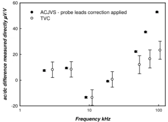
Example of Test Results
Over the last year at NRC, we have conducted numerous tests to characterize the ACJVS system between 2 mV and 200 mV and frequencies 2.5 kHz to 1 MHz. Fig. 2 shows, as an example, results of characterizing a WS using the ACJVS and a thermal voltage converter (TVC), at 100 mV, in the frequency band between 2.5 kHz to 100 kHz. The ACJVS data were averaged over several runs; type-A pooled standard deviation was approximately 0.6 V/V. The probe-leads correction was measured
experimentally. The TVC error bars show the best NRC uncertainty (k=2) assigned to the WS characterization by use of a TVC. The difference between the two methods is less than 1 µV/V at 2.5 kHz. The increasing disagreement between the two methods above 20 kHz is due most likely to not fully removed probe leads error. Details of the test results will be discussed at the conference.
Final Remarks
An ACJVS system based on a pulse-driven NIST array has been established at NRC. A thermal standard was compared to the ACJVS at (2, 10, 20, 100, 200) mV at the frequency band 2.5 kHz to 100 kHz (and up to 1 MHz with reduced accuracy). The correction for the ACJVS leads was measured experimentally. At 100 mV and 2.5 kHz, the ACJVS and TVC results agree better than 1 µV/V. We are working to better understand the ACJVS error sources, to establish corrections and a full error budget, and to incorporate the ACJVS in the NRC standards chain for ac-dc transfer difference. Hardware changes will include upgrading lead connections in the cryoprobe and building electronics to allow for direct comparison of the ACJVS to a MJTC at 100 mV and 200 mV.
References
[1] S.P. Benz and C.A. Hamilton, “A Pulse-Driven Programmable Josephson Voltage Standard,” Appl. Phys. Lett., vol. 68, no. 22, pp. 3171-3173, May 1996.
[2] B. Jeanneret, S.P. Benz, “Application of the Josephson effect in electrical metrology,” Eur. Phys. J. Special Topics vol.172, No. 1, pp. 181–206, June 2009.
[3] T.E. Lipe, et al. “Thermal Voltage Converter Calibrations Using a Quantum AC Standard,” Metrologia, vol.45, no.3, pp.275-280, June 2008.
[4] P.S. Filipski, J.R. Kinard, T.E. Lipe, Y.H. Tang and S.P. Benz, “Correction of Systematic Errors due to Voltage Leads in AC Josephson Voltage Standard,” IEEE Trans. Inst. Meas., vol. 58, No. 4, pp. 853-858, April 2009.
Fig. 1. Experimental determination of leads correction. LPF – low pass filter.
Frequency kHz 1 10 100 a c /d c d if fe re n c e m e a s u re d d ir e c tl y µµµµ V /V -20 0 20 40 60
ACJVS - probe leads correction applied TVC
Fig. 2. Comparison of WS calibration using the ACJVS and a TVC, 100 mV on 220 mV range.