HAL Id: hal-01856848
https://hal.archives-ouvertes.fr/hal-01856848
Submitted on 25 Aug 2018HAL is a multi-disciplinary open access archive for the deposit and dissemination of sci-entific research documents, whether they are pub-lished or not. The documents may come from teaching and research institutions in France or abroad, or from public or private research centers.
L’archive ouverte pluridisciplinaire HAL, est destinée au dépôt et à la diffusion de documents scientifiques de niveau recherche, publiés ou non, émanant des établissements d’enseignement et de recherche français ou étrangers, des laboratoires publics ou privés.
Optimal preliminary design of electromechanical
actuators
Marc Budinger, Aurelien Reysset, Toufic El Halabi, Catalin Vasiliu,
Jean-Charles Maré
To cite this version:
Marc Budinger, Aurelien Reysset, Toufic El Halabi, Catalin Vasiliu, Jean-Charles Maré. Optimal preliminary design of electromechanical actuators. Proceedings of the Institution of Mechanical Engi-neers, Part G: Journal of Aerospace Engineering, SAGE Publications, 2013, 228 (9), pp.1598 - 1616. �10.1177/0954410013497171�. �hal-01856848�
Optimal preliminary design of electromechanical actuators
Marc Budinger 1*, Aurélien Reysset 1, Toufic El Halabi 1, Catalin Vasiliu 2 and Jean-Charles Maré 1. 1 Université de Toulouse, INSA/UPS, Institut Clément Ader, Toulouse, 31077, France.
2 Polytechnic University of Bucharest, Bucharest, 060032, Romania.
ABSTRACT
This paper presents a methodology for the optimal preliminary design of electro-mechanical actuators. The main design drivers, design parameters and degrees of freedom that can be used for preliminary design and optimization of EMA are described. The different types of models used for model based design (estimation, simulation, evaluation and meta-model), and their associations are presented. The process preferred for its effectiveness in terms of flexibility and computational time is then described and illustrated with the example of a spoiler electromechanical actuator. The proposed approach, based on meta-models obtained using the surfaces response methods and scaling laws models, is used to explore the influence of anchorage points and transmission ratio on the different design constraints and the overall mass of the actuator.
Keywords: design exploration, electromechanical actuator, flight control, inverse problem, inverse simulation, Modelica, Meta-Models, Response Surface Methodology, scaling laws, spoiler.
NOTATION
Pseudonyms
DOE Design Of Experiments
EBHA Electrical Back-up. Hydraulic Actuator EHA Electro-Hydrostatic Actuator
EMA Electro Mechanical Actuator MDO Multi-Disciplinary Optimization MEA More Electric Aircraft
MTBF Mean Time Between Failures
PbW Power-by-Wire
RSM Response Surface Method
RMC Root Mean Cube
RMS Root Mean Square
TVC Thrust Vector Control
Variables and constraints
Amax Maximal acceleration of mechanical profile
Cth Thermal capacitance
dcomp Diameter of component (with comp the name of component)
f(x) Objective function
Fmax Maximal force
g gravity acceleration
g(x) Constraint function (inequality)
h(x) Constraint function (equality)
J Inertia
Jmax Maximal Jerk of mechanical profile
kjam Oversizing coefficient for jamming constraints
ktherm Oversizing coefficient for thermal constraints
kvib Oversizing coefficient for vibration constraints
L Length of actuator
lcomp Length of component (with comp the name of component)
Mcomp Mass of component (with comp the name of component)
tm Motion time of mechanical profile
Vmax Maximal speed of mechanical profile
Xmax Displacement of mechanical profile
x Design variables
xa, ya Anchorage point coordinates
xt, yt Transmission point coordinates
α Constant Jerk ratio of mechanical profile
β Constant speed ratio of mechanical profile
θ Temperature increase
ηcomp Efficiency of component (with comp the name of component)
πi dimensionless parameters
1. CONTEXT
The current technical developments in aviation aim at making aircraft more competitive, greener and safer. The more electric aircraft (MEA) offers interesting perspectives in terms of performance, maintenance, integration, reconfiguration, ease of operation and management of power [1] [2].Using electricity as the prime source of energy for non-propulsive embedded power systems is considered by aircraft makers as one of the most promising means to achieve the above mentioned goals. Actuation for landing gears and flight controls is particularly concerned as it is one of the main energy consumers. This explains why, during recent years, a great effort has been put into the development of Power-by-Wire (PbW) actuators at research level (e.g. POA, MOET, DRESS and ACTUATION 2015 European projects). This recently enabled PbW actuators to be introduced in the new generation of commercial aircraft [3] [4], in replacement of conventional servo-hydraulic ones (e.g. Boeing B787 EMA brake or spoiler, Airbus A380 EHA and EBHA). On their side, space launchers are following the same trend for thrust vector control (TVC) as illustrated by the European VEGA project [5] and NASA projects [6]. However, these technological step changes induce new challenges, especially for the preliminary design process for actuation systems and components which cannot simply duplicate former practices.
Section 2 sums up the main requirements, design drivers and design choices for EMA design. This section also describes the different types of models needed. The different possible associations for those models are then presented, and the most efficient and flexible process will be described in details. Section 3 illustrates the different steps, models and tools for the presented methodology with the case study of a spoiler EMA.
2. MODEL BASED DESIGN FOR ELECTROMECHANICAL ACTUATION SYSTEMS
Figure 1 shows the V-cycle design [7] of a mechatronic system such as an EMA (architecture is described in part 3.1). The described methodology is dedicated to the descending branch of the V-cycle corresponding to preliminary optimal sizing and device parts features synthesis. The inputs are the objectives and design constraints coming from the specifications document or the chosen architecture. As output components (rod end, roller or ball screw, gear reducer, brushless motor ...) specifications are generated in order to obtain an assembled actuation system which fully meets upper requirements.
Figure 1: V-cycle design for a mechatronic system
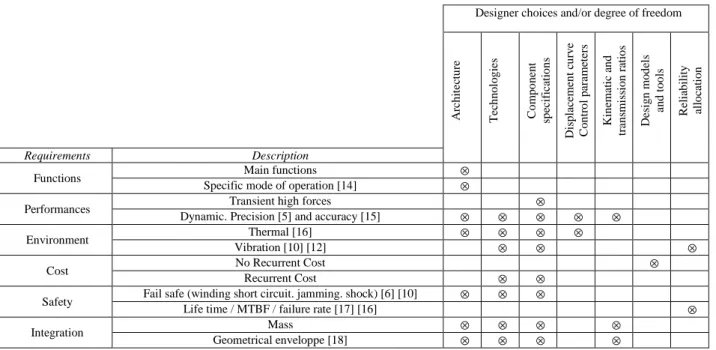
As contributors to the safety of embedded critical functions, aerospace actuators are subjected to numerous specific design requirements. These requirements are translated into design constraints which the designer must meet by discerning choices. Based on recent examples [5] to [13]. Table 1 summarizes these design constraints, design degrees of freedom and their possible interactions. One can notice that the designer choices are numerous; their impact coupled and they should address multiple domains. The study and comparison of different possible architectures must thus be supported by efficient design methodologies.
Table 1: Main design drivers and designer choices during EMA design
Designer choices and/or degree of freedom
A rc h it ec tu re T ec h n o lo g ie s C o m p o n en t sp ec if ic at io n s D is p la ce m en t cu rv e C o n tr o l p ar am et er s K in em at ic a n d tr an sm is si o n r at io s D es ig n m o d el s an d t o o ls R el ia b il it y al lo ca ti o n Requirements Description
Functions Main functions ⊗
Specific mode of operation [14] ⊗
Performances Transient high forces ⊗
Dynamic. Precision [5] and accuracy [15] ⊗ ⊗ ⊗ ⊗ ⊗
Environment Thermal [16] ⊗ ⊗ ⊗ ⊗
Vibration [10] [12] ⊗ ⊗ ⊗
Cost No Recurrent Cost ⊗
Recurrent Cost ⊗ ⊗
Safety Fail safe (winding short circuit. jamming. shock) [6] [10] ⊗ ⊗ ⊗
Life time / MTBF / failure rate [17] [16] ⊗
Integration Mass ⊗ ⊗ ⊗ ⊗
Geometrical enveloppe [18] ⊗ ⊗ ⊗ ⊗
2.2. Models needs for electromechanical preliminary design
To accelerate the design process, a general trend is to extend the role of modelling in design and specification [7] [19]. At preliminary steps of system design, different types of models are needed in order to get a complete sizing: simulation, estimation and evaluation models.
The objective of simulation models is to calculate all the variables of power, energy (force, speed, temperature ...) useful for the components selection. The transient simulation of an EMA is becoming mandatory because, unlike hydraulic actuators, some strong coupling exists between the transient power demand, the thermal behavior of motors, the inertia loads and the fatigue of mechanical components. These simulations are usually based on lumped parameters models [20], also called 0D-1D models, run either in direct or inverse mode [21] [22] in environments such as Matlab/Simulink, Dymola [23], AMESim [24]... The paper [22] describes the use of inverse simulation with Modelica for actuators sizing. Yet, to run this kind of models, which only suits for analysis and not for validation, components parameters may be known, that is why some other types are needed.
Estimation models allow to estimate from a reduced set of independent parameters (ex: max load, stroke) all
the dependent parameters/component characteristics: simulations (ex: inertia, efficiency…), integration (ex: mass, dimensions) and validation of safe operating area (ex: max speed, degradation parameters…). This is a way to replace components datasheets when they are not available (often the case for aerospace application) or to speed up the design exploration (analysis of different scenarios, optimization…). The reference [14] describes some estimation models based on scaling laws for the main components of an electromechanical actuator.
The last model is the evaluation model whose goal is to check the ability of a component to operate in its safe operating area for the required lifetime and reliability. The paper [16] describes the possible models and ways of implementing them in system simulation environments. Figure 2 describes the information exchanges between those different models and defines the structure suitable for model-based design of mechatronic systems. Decision making can be performed either manually as in [22] or automatically as described in the following paragraph.
2.3. Models implementation and possible associations
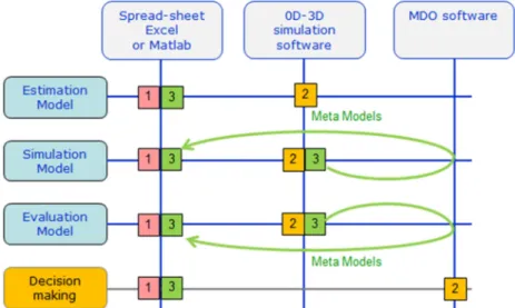
These defined models can be implemented in different types of environment. Decision making can be achieved by different optimization methods. Figure 3 illustrates three different options:
1. All the models are implemented in a computer algebra environment (Matlab, Excel). The design and optimization are done in the same environment. This solution does not address time transient phenomena problematic. However, it has the advantage suit well taking into account multiple design criteria and exhibit fast optimization. Examples of such implementation were presented in [25] [ [26] and [15] ;
2. All the models are implemented in a simulation environment for algebraic differential equations (e.g. Modelica) and the optimization is done by external MDO software [27]. This solution allows managing fine simulation models with time transients. Yet, one main drawback is the optimization times which can become very long. Examples of such implementations are given in [28] [29] ;
3. A mix of the first two solutions can be achieved with a compact representation of time-consuming temporal simulations using meta-modeling technics [30]. This solution allows to easily manage multiple design criteria and to obtain reasonable optimization time. However special care should be addressed to the accuracy of meta-models.
This last solution will be developed in the paper. The use of meta-optimization is common for studies with finite elements methods in various fields [31]. But here, the meta-models applied to 3D multi-body and 0D/1D simulations and the estimation models based on scaling laws are used to speed up the optimization of the actuator.
Figure 3: Models implementations and associations
2.4. Proposed methodology for optimal design of EMAs
As defined by [32] [33], a methodology is a collection of related process, methods and tools where: - A process is a logical sequence of tasks performed to achieve a particular objective (“WHATs”); - A method consists of techniques for performing a task (“HOWs”);
- A tool is an instrument that, when applied to a particular method, can enhance the efficiency of the task (supports the “HOWs”).
Table 2 presents those three aspects. The main functional requirements and design degrees of freedom are given as inputs for this process. The actuator architecture and combination of power transmission components are also defined to meet the application functional requirements.
Table 2: Synthesis of the proposed methodology Process
(« WHATs »)
Methods (« HOWs ») Tools (supports the
« HOWs »)
1 Sizing scenarios definition (section 0)
1.1 Determine components design drivers. Checklist by fields (mechanical. Electrical, thermal ...) or components. 1.2 Determine sizing scenarios to verify the design
drivers and the actuator functions.
-Verification matrix
2 Determination of the active design drivers
2.1 Perform initial power sizing (not optimized) using a "sizing wave" procedure and complementary simulations.
In-house Modelica library : -Inverse simulation (Modelica). -Estimation models (scaling
(section 0) laws) . 3 Sizing procedure setting-up and optimization problem definition (section 0)
3.1 Determining the calculation steps order for the sizing procedure.
-N² diagram.
3.2 Define the optimization problem. -Influence diagram.
4 Creation of meta-models
(section 3.5)
4.1 Non explicit calculations from step 3 may be replaced by meta-models.
-RSM models.
5 Design optimization (section 0)
5.1 Identify important parameters with quick exploration and reduce design space.
-Excel table.
5.2 Optimize in the reduced space. -Excel solver
6 Validate « optimal » solution (section 3.7)
6.1 Repeat sizing performed during step 2 to the result obtained in step 5.
In-house Modelica library : -Backward simulation
(Modelica).
-Estimation models (scaling laws).
3. SPOILER ACTUATOR CASE STUDY
3.1. Case study and actuator architecture presentation
It is proposed in this section to illustrate the design methodology using the case of a linear EMA. This actuator is actuating a spoiler/airbrake with typical specifications for a business jet. The so called spoiler is only performing airbrake functions. Thereby possible primary flight control functions of commercial aircrafts are not taken here into consideration: control surfaces are thus controlled symmetrically with a given displacement curve.
3.1.1.Main functional requirement
The main functional requirement for the actuator is to move the mechanical load to 3 predetermined positions (0. 20 and 50 °) against mainly the aerodynamic forces. The retracted position (0°) has to be hold without energy consumption. Anchorage points on the structure and the control surface are not imposed by the aircraft maker and therefore, can be a degree of freedom for the design process.
The severe failure rate requirements at aircraft level are achieved with resort to multiple control surfaces. Thus the requested failure rate of one actuator is compatible with a simplex architecture. However minimizing mass is an objective. The architecture should also be safe regarding different critical cases :
- no dissymmetric deflection during a power loss : the actuator should thus fail-freeze;
- no degradation of the surface control during gust : in order to avoid mechanical damage, a load limitation must be performed by folding down the control surface;
- no degradation of the actuator or the surface control due to a jamming of the control surface during the actuator motion.
3.1.2.Actuator architecture
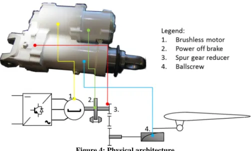
The physical architecture of the actuator is based on the Moog linear actuator presented in [34]. This architecture should be also close to the EMA actuator actuating several spoilers of the commercial aircraft Boeing 787 [32]. Figure 4 presents a picture of the Boeing 787 actuator prototype and describes an association of component meeting the requirements of section 3.1.1 where:
- The selected technologies, brushless motor and screw, meet the main function with a minimum mass compared to a direct drive solution. The main drawback of both screw and reducer is the jamming failure mode. This failure mode is however not an issue for the fail-freeze specification. Even if the 787 spoiler actuator uses a ball screw, a roller screw will be used instead during the sizing and optimization of this specific application.
- A one stage spur-gear reducer with intermediary wheel allows at the same time to adapt the brushless motor speed and the parallel axes distance (distance between motor and roller screw axes).
Figure 4: Physical architecture
To meet the functions described in the previous paragraph, a control architecture with a force feedback sensor can be used. Figure 5 gives the principle of this last one. Main loops for typical control architecture are: current, speed and position loops. Load control can also be implemented like in the examples of aerospace actuators described in [5] and [36] to limit external perturbations (high frequency vibration, gust load…). In this case the load control is realized through a force feedback to torque control of the motor. The activation of the load control also leads to decrease of the authority of the main position loop to allow the drop of the surface in presence of excessive air loads.
Figure 5: Control architecture
3.2. Task 1 : Sizing scenarios definition
3.2.1.Definition of design drivers and induced design drivers
The objective of task 1 is to represent by a set of scenarios the degradation phenomena and functions of the actuator. Those scenarios form the basis for the calculations to be carried out during the design.
The degradations of the components can be of two different types, depending on the phenomena dynamics: - What is called rapid degradation (e.g. permanent deformation, fracture, maximum insulator
temperature…) on transient power demand. They must be avoided to ensure maximum performance of the actuator.
- What is called gradual degradation (e.g. mechanical fatigue, insulator ageing…). They must be such as to ensure endurance and reliable operation of the actuator throughout its life.
Additionally, the components present some imperfections which increase stresses on themselves (e.g. inertia) or on other components (e.g. friction, copper losses…) and can create new critical cases (e.g. high stress induced by jamming of inertial loads). Those imperfections are called here induced design drivers.
The determination of the components design drivers can be assisted by checklists for the different technologies or components.
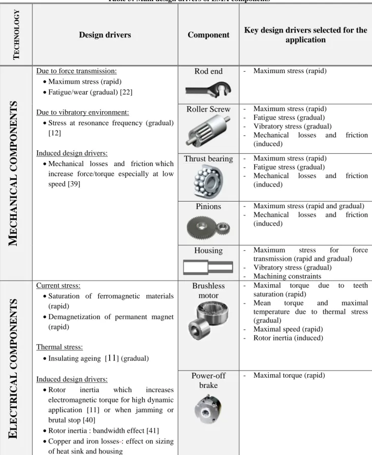
Table 3 is a possible representation of those lists. Some references are quoted to allow further study or justify the importance of listed items. The paper [14] also recalls those points.
3.2.3.Sizing scenarios and corresponding mission profiles
They should permit to validate the fact that the solution meets all the functions and associated performance of section 3.1.1 and is not submitted to inappropriate damages listed in section 3.2.2. In the case of EMAs, those scenarios are mainly characterized by finite time dependent mission profiles.
For the present case study, the following examples of scenarios can be defined:
a) To take into account the mechanical stresses a mission profile representative of the maximum speed. For maximum load and fatigue phenomena: a succession of extension / retraction for different speeds of the aircraft;
b) To represent the thermal stresses: holding of the control surface opened at 50 ° and submitted to full load for 3 minutes within an ambient temperature of 30 ° C;
c) To take into account the effect of the motor inertia: a jamming of the control surface occurring at full speed ;
d) To ensure adequate dynamics during load limitation: an active retraction of the spoiler under the effect of a gust ;
e) To take into account the vibratory environment: a lateral sinusoidal acceleration of 10g between 5 and 2000 Hz [37] (validation of screw and housing resonant frequencies and induced stresses).
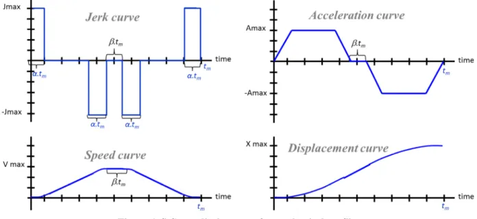
Scenario a) to d) can be described by transient simulations of 0D-1D models. Figure 6 describes spoiler angle time evolution for the a) mechanical mission profile. The paper [35] explains how to take into account scenario e) during the preliminary design phase using analytical models. Table 4 is a verification and validation matrix to check that all design features or drivers are covered by those five scenarios.
Table 3: Main design drivers of EMA components T EC H N O L O G Y
Design drivers Component Key design drivers selected for the
application
M
E
C
H
A
N
IC
A
L
C
O
M
P
O
N
E
N
T
S
Due to force transmission:
•Maximum stress (rapid)
•Fatigue/wear (gradual) [22] Due to vibratory environment:
•Stress at resonance frequency (gradual) [12]
Induced design drivers:
•Mechanical losses and friction which increase force/torque especially at low speed [39]
Rod end - Maximum stress (rapid)
Roller Screw - Maximum stress (rapid) - Fatigue stress (gradual) - Vibratory stress (gradual)
- Mechanical losses and friction (induced)
Thrust bearing - Maximum stress (rapid) - Fatigue stress (gradual)
- Mechanical losses and friction (induced)
Pinions - Maximum stress (rapid and gradual) - Mechanical losses and friction
(induced)
Housing - Maximum stress for force transmission (rapid and gradual) - Vibratory stress (gradual) - Machining constraints
E
L
E
C
T
R
IC
A
L
C
O
M
P
O
N
E
N
T
S
Current stress:•Saturation of ferromagnetic materials (rapid)
•Demagnetization of permanent magnet (rapid)
Thermal stress:
•Insulating ageing [11] (gradual)
Induced design drivers:
•Rotor inertia which increases electromagnetic torque for high dynamic application [11] or when jamming or brutal stop [40]
•Rotor inertia : bandwidth effect [41]
•Copper and iron losses: effect on sizing of heat sink and housing
Brushless motor
- Maximal torque due to teeth saturation (rapid)
- Mean torque and maximal temperature due to thermal stress (gradual)
- Maximal speed (rapid) - Rotor inertia (induced)
Power-off brake
Figure 6: S Curve displacement for mechanical profile
Table 4: Verification matrix
Checking points Scenarios
Type Description a ) M ec h a n ic a l p ro fi le b ) T h er m a l p ro fi le c) J a m m in g a t fu ll sp ee d d ) G u st a n d lo a d li m it a ti o n e) V ib ra to ry en v ir o n n m en et
Functions Displace and hold the spoiler in position ⊗ ⊗
No degradation due to jamming ⊗
Gust load limitation ⊗
Design drivers Maximum stress for mechanical components
⊗
Maximum speed for mechanical
components ⊗
Fatigue mechanical components ⊗
Induced effects of efficiency and friction ⊗ ⊗ ⊗
Stress due to vibrations ⊗
Maximal torque for motor and power off brake
⊗
Maximum speed for motor ⊗ ⊗
Maximum temperature for brushless motor ⊗
Induced effect of inertia ⊗ ⊗
3.3. Task 2 : Initial sizing and active design drivers
In the considered case study, the initial sizing aims at the identification of the active design criteria and helps simplifying the models used for the selection of the actuator components. This first design is made for a given set of anchorage and transmission points that will be modified during the optimization phase coming later on. But, even for this first design, different types of simulation models are used.
3.3.1.Sizing wave
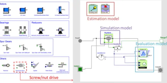
An in-house Modelica library for the preliminary design of EMAs, shown in Figure 7, has been developed to implement all the components models presented in Section 3.1.2 according to the structure of Figure 2. Object orientated and class inheritance properties of Modelica language facilitate the implementation of such a structure. The models are thus structured in a way that they can combine inverse simulation together with parameters estimation (using scaling laws). Components from the created Modelica library can be combined to represent various EMAs’ architectures. The studied architecture has been sized up with a few number of simulations by following the "sizing wave" process described in paper [22] where inverse simulation means to
size successively each component propagating power from the load to the power source. This step is usually called power sizing and components selection, with respect to previously defined scenarios a) and b).
a) Library structure
b) Components model from the library
c) Spoiler actuator model
Figure 7: In-house Modelica library for the preliminary design of EMAs From this initial power sizing, it is interesting to note that:
-The motor inertia does not impact the maximum electromagnetic torque because the load is mainly aerodynamic and can be considered as a nonlinear stiffness depending on airspeed and surface steering; -The friction models of mechanical components have to be taken into account for the motor sizing; -Thermal aspect is really important for motor selection;
-The requested lifetime and reliability are not critical for this case study and can be neglected.
-According to the reduction ratio, the mechanical components may be oversized in order to bear the stress induced by the jamming of the spoiler running at full speed.
-The maximum motor torque must allow a retraction fast enough to limit extreme load occurring during a gust.
For scenario e), the length of the actuator is relatively short that is why the vibratory environment has no significant impact on the housing induced stress. Therefore, the main design driver will be the minimal machining thickness constraint.
3.3.3.Initial sizing overview
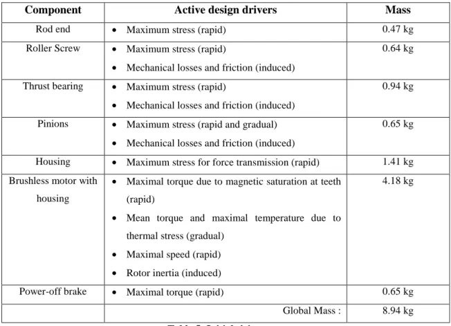
Table 5 gives an overview of the masses, estimated thanks to scaling laws, for the various components of the EMA and the related criteria leading to their selection, criteria which should be considered during optimization (task 3).
The process leading to those results is the following:
- Choose first the anchorage points on structure farthest of the hinge axis to facilitate actuator integration;
- Select average values for all other parameters (defined in part 3.4.3).
- If motor thermal constraint is not validated, increase motor size (i.e. thermal over-sizing coefficient). - If jamming induced stress constraint is not validated, increase mechanical safety coefficient.
Component Active design drivers Mass
Rod end • Maximum stress (rapid) 0.47 kg Roller Screw • Maximum stress (rapid)
• Mechanical losses and friction (induced)
0.64 kg
Thrust bearing • Maximum stress (rapid)
• Mechanical losses and friction (induced)
0.94 kg
Pinions • Maximum stress (rapid and gradual)
• Mechanical losses and friction (induced)
0.65 kg
Housing • Maximum stress for force transmission (rapid) 1.41 kg Brushless motor with
housing
• Maximal torque due to magnetic saturation at teeth (rapid)
• Mean torque and maximal temperature due to thermal stress (gradual)
• Maximal speed (rapid)
• Rotor inertia (induced)
4.18 kg
Power-off brake • Maximal torque (rapid) 0.65 kg Global Mass : 8.94 kg
Table 5: Initial sizing
3.4. Task 3 : Sizing procedure and optimization problem definition
3.4.1.Objectives
The objective of this step is to define the sizing problem as an optimization problem which can be formulated mathematically as follows:
Minimize objective function f(x)
Subject to equality and inequality constraints h(x) = 0, g(x) < 0
Where:
-The goal, here the global mass, is the objective function f;
-Design alternatives are expressed by a set of values assigned to the design variables x within a design domain;
-Constraints (h & g) limit the number of alternatives to those satisfying physical principles and design specifications, that is to say feasible design.
The functions (f, g, h) can be explicit or implicit, algebraic or realized by subroutines that solve iteratively systems of differential equations. The goal of this task is to define those functions within a sizing procedure. The calculation steps of the sizing procedure should be time efficient, and to do so, only algebraic explicit functions without iteration loops are to be implemented. The number of design parameters x and constraints g and h should also be minimized to reduce design search space and thus, optimization time.
3.4.2.Sizing procedure definition
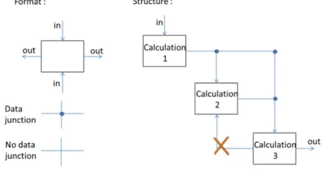
The sizing procedure is the sequence of calculation steps to be carried out for defining the actuator components. As mentioned before, step 2 allows to determine the minimum number of design criteria to consider in order to have a correct but lighter optimization problem. This procedure can be represented as an algorithm or flowchart. The Design-Structure-Matrix (DSM) [42] or N² diagrams [43] can also represent this sequence. All those representations are useful for the assessment of the models needed and exchanged quantities and for the visualization of the sequencing quality. Figure 8 recalls the principle of representation by N² diagrams. The objective is here to avoid any information feedback/loop thanks to a good choice of calculations order or by introducing additional constraints and design parameters being managed by the optimization algorithm. In the case of DSM matrix representation, the objective is to obtain a triangular matrix.
Figure 8: N² diagram principle
Figure 9 represents the sizing procedure for the EMA of the spoiler for the present case study. As an example, the bearing is sized before the roller screw in order to get the values necessary to define the length of the screw. Constraints have been added in order to make the design matrix triangular: calculations of the resonant frequency of transversal vibrations of the screw, of motor temperature and of maximum load during jamming. The corresponding oversizing coefficients are added to the first set of design parameters and are driven by the optimization solver. Some models, as the multi-body and thermal models, require long time dependent simulations: their behavior will be translated into explicit mathematic functions thanks to meta-modeling techniques (Section 3.5).
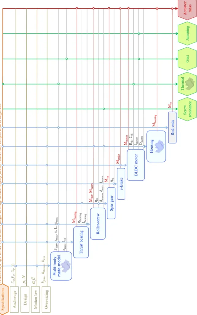
3.4.3.Optimisation problem definition
The optimization problem can be defined only when the sizing procedure is known. To represent it, an influence diagram [44], Figure 10, can be used. Here:
-The main design parameters are internal reduction ratios (roller screw pitch p and reducer ratio N), integration parameters (anchorage to airframe xa, ya and transmission to load xt, yt points), shape of the
displacement curve (α, β displacement curve parameters as described in Figure 6), oversizing coefficient (jamming coefficient kjam, brushless motor thermal coefficient ktherm and screw vibration coefficient kvib);
-The main objective is the total mass obtained by the sum of the masses of all the components estimated thanks to scaling laws;
-The constraints are used to represent some design drivers which cannot be addressed in a direct way by the sizing procedure. Oversizing coefficients enable to take care of these constraints during optimization.
Figure 10: Influence diagram of the optimization problem
3.5. Task 4 : Meta-models synthesis
3.5.1.Process
To facilitate and accelerate the design exploration during optimization, it is more suitable to use models with only static parameters and without time dependent variables. The meta-modeling techniques [30] enable to extract a response surface from a set of simulation results. The calculated meta-models have here a polynomial form to facilitate their easy implementation into a calculation sheets (e.g. in the MS Excels environment) (Task 5, section 3.6). The generation of a meta-model follows the process shown Figure 11 and is performed here with the Optimus software [45].
3.5.2. Multi-body meta-model
The meta-models representing multi-body simulation link the effect of actuator geometric integration (anchorage xa, ya and transmission xt, yt points parameters, Figure 12) and the displacement curve form (α, β
displacement curve parameters) to useful sizing criteria as stroke, maximum speed, maximum load, RMS and RMC load. The identification of the main factors is done through screening. This screening step allows to conclude that for this application case, parameters α and β have only an influence on the maximum speed.
The meta-model building is realized here with a Latin Hypercube DOE of 1000 experiments. It is important to note that the model quality depends on the mathematical function used to represent the behavior [46] : for example assuming 1/Fmax has a polynomial form better suits than expressing directly Fmax as a polynomial
function. With a second order development, the meta-model provides a regression coefficient R better than 0.999 for all calculated values.
Figure 12: Anchorage and transmission points 3.5.3.Thermal meta-model
The meta-model described here will be used to get the maximal temperature of the motor winding during scenario b) (Cf section 3.2.3). For this example, the main factors' identification is done by dimensional analysis [47] [48] which will reduce the number of parameters to be studied without any loss of information. The thermal model of a motor given in Figure 13, distinguish the temperature of the winding from the temperature of the yoke by using a two thermal bodies model.
The relationship to define is characterized by 6 parameters: - The heat capacity of the winding Cth1;
- The heat capacity of the yoke Cth2;
- The thermal resistance between the winding and the yoke Rth1;
- The thermal resistance between the yoke and the ambient air Rth2;
- The thermal losses Pth;
- The temperature increase θ of the winding after a given time t.
Buckingham theorem [47] [48] can be used to reduce this number to 4 dimensionless parameters: ) , , ( 1 2 3 4 π π π π = f with 2 1 1 th th
R
R
=
π
, 2 1 2 th thC
C
=
π
, 1 1 3 th thC
R
t
=
π
and th thP
R
1 4θ
π
=
With a Latin Hypercube DOE of 100 experiments, a third order development provides a coefficient of regression R better than 0.99 for this function. The desired function could also be derived from the direct solution of differential equations of the lumped parameters model shown Figure 13. The aim here is to show that the designer can however get an algebraic expression from any numerical models. The meta-models thus allow him to focus more on the sequencing of calculations than on the solving of each calculation.
Figure 13: Thermal model of the motor
3.6. Task 5 : Optimization and design exploration
The optimization process has been implemented using spreadsheet in the MS Excel environment taking benefit of the work done at previous steps: structuring the problem (task 3) and synthetizing meta-models (task 4). The design procedure is thus explicit and easily adaptable to any solvers or exploration functions (e.g. data tables, scenarios). Table 6 summarizes the optimal results obtained after 20 minutes of computation on a standard PC (Intel core i5 processor) with nonlinear GRG solver and Multi-Start option. The optimization has been carried out for different integer values screw pitches in millimeters to take into account manufacturing constraints and to evaluate the effect of this important parameter. Figure 14 gives the mass distribution for the optimal solution obtained using a 5mm/rev screw pitch.
Parameters Range Initial sizing Optimal sizing (discrete screw pitch)
Pitch p [mm] [2;5] 5 2 3 4 5 Reducer ratio N [-] [1;5] 3.00 2.44 4.40 5.00 4.99 Transmission xt [mm] [-50;0] -25.0 -33.4 -33.7 -37.0 -50.0 Transmission xt [mm] [-80;-30] -55.0 -80.0 -80.0 -80.0 -80.0 Anchorage xa.[mm] [-400;-300] -400.0 -400.0 -400.0 -396.3 -400.0 Anchorage xa [mm] [-150;50] -150.0 -149.8 -149.7 -148.0 -150.0 S curve coefficient β [-] [0.05;04] 0.25 0.4 0.4 0.4 0.4
Jamming oversizing kjam [-] [1;4] 1.02 1.47 1.48 1.43 1.44
Thermal oversizing kther [-] [1;4] 1.10 1.18 1.21 1.20 1.19
Vibration oversizing kvib [-] [1;4] 1 1 1 1 1
Total mass [kg] 8.94 6.42 6.01 5.99 5.92
Figure 14: Mass distribution of an optimal sizing (pitch of 5 mm/rev)
It is important to remark that the proposed process generates a gain of 33% on the mass in comparison with the initial sizing of section 0. The initial sizing has been done choosing an anchorage point on the structure which facilitates the geometrical integration and taking average values for lever arm. At this point, a major part of the actuator mass was devoted to the brushless motor (almost 50%) due to a low global reduction ratio.
The parameters obtained for the optimal solutions highlight that:
-As inertial torque due to the motor inertia has limited impact on the maximal electromagnetic torque, the S curve parameter, β (constant speed ratio), has been maximized in order to minimize motor maximal speed. The conclusion can change if accelerations are higher and/or load features are different as for TVC actuators [12].
-The lever arm has been maximized to minimize load and component masses. The conclusion can be different if the actuator is longer, as for a landing gear extension/retraction actuator, where the housing mass, representing the major part of actuator mass, increases significantly with its length in order to resist to transverse vibratory stress [35].
- The global reduction ratio is limited here by the jamming requirement. This ratio can be different if the expected lifetime is greater (as for an aileron actuator) or for a different type of aircraft.
The different pitch values can be compared through design explorations around the optimal points. The graphs given in Figure 15 illustrate the evolution of the overall mass and main design constraints according to the two most influent parameters, i.e. the location the transmission point (parameters xt and yt). The other design
parameters are set to the optimal values of Table 6. Each constraint is represented with dotted lines and defines a feasible solution search area with upper and lower bounds. For a 2 mm pitch, Figure 15a), the feasible design field is clearly limited by all these constraints. Therefore, the designer has a poor design flexibility. While for a 5 mm pitch, Figure 15b) the feasible search space is much bigger. The designer can thus choose a slightly different solution without adding significant weight to the actuator, while increasing robustness in regards to the assembly and jamming constraints.
a) 2 mm/rev pitch b) 5 mm/rev pitch
3.7. Task 6 : Validation
For validation, it is particularly important to check that for the optimal parameters:
• The response surface approximation, established during task 4 (section 3.5), is sufficiently accurate. Otherwise, it is necessary to construct the response surface again, refining mathematical formula around the point of interest;
• The simplification assumptions established during task 2 (section 0), remain effective. If a design driver defined as inactive during the initial design becomes dominant for the optimal configuration, this new constraint must be integrated and the optimization launched again.
In the case study considered here, time domain simulations validate the results obtained within spreadsheets. It may also be interesting to validate the estimation models results (extrapolation of selected industrial components features) comparing them to real industrial components extracted from manufacturer datasheets.
Table 7 compares optimal results for a 5mm/rev screw pitch using scaling (column 1) to real industrial components (column 2). The mass deviation gives an idea of the mass penalty which may be due to components standardization and discretization of a product range. Yet, the scaling laws, in the case of a specific design as typically encountered till now in aerospace domain, allow specifying or estimating new components features.
Component definition Scaling laws estimation for optimal configuration
Nearby industrial components
Rod-end 58kN (0.34kg) SKF-SAKB22F 58.5kN (0.46kg)
Plain bearing 58kN (0.04kg) SKF-GE17C 56kN (0.05kg)
Screw 5mm/tr-18mm-58kN (0.34kg) SKF-BRC21x5 (0.47kg)
Nut Ø38mm. 54mm (0.24kg) Ø45mm. 64mm (0.40kg)
Thrust bearing 58kN (0.76kg) SKF-5308E 65.5kN (1.15 kg)
Reducer 16/40/80 module 1
(0.02kg/0.10kg/0.41kg)
QTC-MSGA1-20/35/100 (0.02kg/0.09kg/0.68kg)
Motor (frameless) 6.6Nm (linear)
(1.76kg) KOLLMORGEN-RBE02114 6.4Nm (2.18kg) Motor (housing) (0.24kg) Brake 4.5N.m (0.33kg) OGURA-TMB-0.6 (6Nm) (0.32kg) Housing d1/e1/d2/e2 38/2/87/2mm (1.33kg) 38/2/87/2mm (1.33kg) Total mass ≈6.0kg ≈7.1kg
Table 7: Scaling laws and on the shell components comparison
Solution using standard components does not differ a lot from obtained “optimal” configuration, with a difference lower than 20% on the overall mass. This difference is mainly due to weak manufacturer product choices when considering thrust bearing and roller-screw components.
It may be noted that the overall methodology is well suited to collaborative work and development of multi-domain systems:
-The rationalization of the sizing scenarios determination in step 1 is well suited to group meetings;
-The distribution of work is intrinsic to the methodology. The system engineer can define the sizing procedure (step 2) and achieve the final optimization in excel (step 5). Experts of different technical areas (kinematics and mechanical power transmission, thermal of electrical motors. ...) can establish meta-models;
-Thanks to distinction between simulation models and estimation models (scaling laws), the management of supplier’s data are facilitated. The updating of scaling laws references enables to take into account technical developments or to compare some technologies;
-Meta-modeling takes into account multiple design criteria within multiple domains; -Verification / validation are done through steps 1 and 6.
4. CONCLUSION
A technology shift towards more electric solutions is emerging in aerospace actuation. New technology brings new challenges, especially for the preliminary design process of actuation systems and components that cannot simply duplicate former practices. In this way, it is no longer meaningful to proceed to static sizing by typical operating points as was possible for hydraulic actuators that do not induce strong couplings in design. Instead, it is necessary to take into account transient mission profiles covering all possible sizing drivers (e.g. maximum speed and torque, fatigue, thermal behaviour, vibrations and shocks) and addressing various design criteria (e.g. geometrical envelope, weight and reliability). For this purpose, appropriate models and methodologies should be developed to support an efficient optimal preliminary design. In this paper, a structure for component model has been presented in order to transform the system simulation tools into design tools. This model structure is based on three different types of models: estimation, simulation and evaluation models. This paper also mainly describes a six step design methodology to define the sizing scenarios to consider and gradually transform the corresponding transient simulations into design models combining judiciously scaling laws and response surface approximation into selection procedures established using N2 diagram. This decomposition facilitates the optimization model, the exploration of the design space, taking into account multiple design constraints. This methodology fits well in a collaborative engineering work for the decomposition of tasks and studies; verification / validation process, the rapid updating of technological references; and the optimization and knowledge management process. This methodology has been illustrated with a study case of an EMA dedicated to spoiler actuation which is realistic and representative of the number of functions, the multiple points of views for design and the different technological domains to take into account in order to achieve preliminary design of an EMA. This case study has illustrated the interest of the methodology and has enabled to describe all the tasks. This methodology is applicable to other configurations (TVC, landing gear actuator…), other technologies (hydraulic, power electronics, control) and even other technical systems.
ACKNOWLEDGMENTS
The work presented was partly funded by the European ACTUATION 2015 project (Modular Electro Mechanical Actuators for ACARE 2020 aircraft and helicopters).
REFERENCES
[1] T. Ford, "More-electric aircraft," Aircraft Engineering and Aerospace Technology, vol. 77, Feb. 2005.
[2] J. A. Weimer, "The role of electric machines and drives in the more electric aircraft," in Electric Machines and Drives
Conference, 2003. IEMDC'03. IEEE International, vol. 1, Jun. 2003, pp. 11-15vol1.
[3] D. van den Bossche, "A380 primary flight control actuation system," in International Conference on Recent Advances
in Aerospace Actuation Systems and Components, Jun. 2001, pp. 1-4.
[4] M. Todeschi, "Airbus – EMAs for flight actuation systems – perspectives," in International Conference on Recent
Advances in Aerospace Actuation Systems and Components, May 2010, pp. 1-8.
[5] G. Dée, T. Vanthuyne, and P. Alexandre, "An electrical thrust vector control system with dynamic force feedback," in
International Conference on Recent Advances in Aerospace Actuation Systems and Components, Jun. 2010, pp. 75-79.
[6] J. R. Cowan and R. A. Weir, "Design and test of electromechanical actuators for thrust vector control," in The 27th
Aerospace Mechanisms Symposium, 1992, pp. 349-366.
[7] VDI, Design methodology for mechatronic systems. Düsseldorf.
[8] D. Fuerst and T. Neuheuser, "Development, prototype production and testing of an electromechanical actuator for a swashplateless primary and individual helicopter blade control system," in 1st international workshop on aircraft
system technologies, Hamburg, Germany, Mar. 2007, pp. 7-19.
[9] J. Hagen, L. Moore, J. Estes, and C. Layer, "The X-38 V-201 Flap Actuator Mechanism," in Proceedings of the 37th
Aerospace Mechanisms Symposium, Johnson Space Center, May 2004.
[10] D. J. Kopala and C. Doel, "High Performance Electromechanical Actuation for Primary Flight Surfaces (EPAD Program Results)," in Recent Advances in Aerospace Actuation Systems and Components, Toulouse, France, Jun. 2001. [11] D. E. Schinstock and D. A. Scott, "Controller Design for EMA in TVC Incorporating Force Feedback," NASA/MSFC,
Tech. rep., 1998.
[12] S. Grand, "Electromechanical actuators design for thrust vector control," in Recent Advances in Aerospace Actuation
Systems and Components, Toulouse, France, Nov. 2004.
[13] P.-Y. Chevalier, S. Grac, and P.-Y. Liegois, "More electrical landing gear actuation systems," in Recent Advances in
Aerospace Actuation Systems and Components, Toulouse, France, May 2010.
electromechanical actuators," Proceedings of the Institution of Mechanical Engineers, Part G: Journal of Aerospace
Engineering, vol. 226, no. 3, pp. 243-259, 2012.
[15] F. Roos, "Towards a methodology for integrated design of mechatronic servo systems," Ph.D. dissertation, KTH, Machine Design, 2007.
[16] J. Liscouët, M. Budinger, and J. .-C. Maré, "Design for Reliability of Electromechanical Actuators," in Recent
Advances in Aerospace Actuation Systems and Components, Toulouse, France, May 2010.
[17] J. Liscouet, J. .-C. Mare, and M. Budinger, "An integrated methodology for the preliminary design of highly reliable electromechanical actuators: Search for architecture solutions," Aerospace Science and Technology, no. 0, pp. -, 2011. [18] M. Budinger, A. Fraj, T. E. Halabi, and J.-C. Maré, "Coupling CAD and system simulation framework for the
preliminary design of electromechanical actuators," in IDMME Virtual Concept, Bordeaux, France, Oct. 2010. [19] INCOSE, Systems engineering handbook, I. T. Product, Ed. 2004.
[20] F. Cellier and J. Greifeneder, Continuous System Modeling, Springer, Ed. 1991.
[21] D. J. Murray-Smith, "The inverse simulation approach: a focused review of methods and applications," Mathematics
and Computers in Simulation, vol. 53, pp. 239-247, 2000.
[22] J. Liscouet, M. Budinger, J.-C. Maré, and S. Orieux, "Modelling approach for the simulation-based preliminary design of power transmissions," Mechanism and Machine Theory, vol. 46, no. 3, pp. 276-289, 2011.
[23] S. E. Mattsson, H. Elmqvist, and M. Otter, "Physical system modeling with Modelica," Control Engineering Practice, vol. 6, no. 4, pp. 501-510, 1998.
[24] H. Auweraer, J. Anthonis, S. Bruyne, and J. Leuridan, "Virtual engineering at work: the challenges for designing mechatronic products," Engineering with Computers, pp. 1-20, 2012.
[25] M. Budinger, T. E. Halabi, and J.-C. Maré, "Optimal preliminary design of electromechanical actuation systems," in «
More electrical » aircraft technologies, Symposium SPEC, Lyon, France, Nov. 2011.
[26] F. Messine, B. Nogarede, and J. .-L. Lagouanelle, "Optimal design of electromechanical actuators: a new method based on global optimization," Magnetics, IEEE Transactions on, vol. 34, no. 1, pp. 299-308, Jan. 1998.
[27] J. Sobieszczanski-Sobieski and R. T. Haftka, "Multidisciplinary aerospace design optimization: survey of recent developments," Structural optimization, vol. 14, pp. 1-23, 1997.
[28] M. Rottach, C. Gerada, T. Hamiti, and P. W. Wheeler, "Fault-tolerant electrical machine design within a Rotorcraft Actuation Drive System optimisation," in Power Electronics, Machines and Drives (PEMD 2012), 6th IET
International Conference on, Mar. 2012, pp. 1-6.
[29] T. El-Halabi, M. Budinger, and J.-C. Maré, "Optimal geometrical integration of electromechanical actuators," in Recent
Advances in Aerospace Actuation Systems and Components, Toulouse, France, May 2010.
[30] T. Simpson, J. Peplinski, P. Koch, and J. Allen, "“Metamodels for Computer-Based Engineering Design: Survey and Recommendations," Engineering with Computers, vol. 17, pp. 129-150, 2001..
[31] A. J. Keane and P. B. Nair, Computational Approaches for Aerospace Design: The Pursuit of Excellence, L. C. U. John Wiley & Sons, Ed. 2005.
[32] J. A. Estefan, "Survey of Model-Based Systems Engineering (MBSE)," Survey of Model-Based Systems Engineering (MBSE), Tech. rep., May 2007.
[33] J. N. Martin, Systems Engineering Guidebook: A process for Developing Systems and Products, I. :. B. Raton, Ed. CRC Press, 1996.
[34] M. A. Davis, "High performance electromechanical servoactuation using brushless DC motors, Technical bulletin 150," MOOG, Tech. rep., 1984.
[35] "Flight control systems," Moog - Navy league:Sea, Air and Space. Special Edition, 2009, www.moog.com. [36] W. S. Schaefer, l. J. Inderhees, and J. F. Moynes, "Flight control actuation system for the B-2 advanced technology
bomber," SAE transactions, vol. 100 (1), n°1, pp. 284-295, 1991.
[37] DOE 160, Environmental Conditions and Test Procedures For Airborne Equipment, standard for environmental test of avionics hardware. Mar. 2005.
[38] F. Hospital, M. Budinger, A. Reysset, and J.-C. Maré, "Preliminary design of linear actuator housings for aerospace vibratory environment," paper submitted to the Machine and Mechanism Theory journal, Elsevier.
[39] J.-C. Maré, "Friction Modelling and simulation at system level – A practical view for the designer," Proceedings of the
Institution of Mechanical Engineers, Part I, Journal of Systems and Control Engineering, vol. in press, 2012.
[40] K. Atallah, S. D. Calverley, and D. Howe, "A Brushless Permanent Magnet Motor With Integrated Torque-Limiter,"
Magnetics, IEEE Transactions on, vol. 43, no. 6, pp. 2498-2500, Jun. 2007.
[44] R. J. Malak, L. Tucker, and C. J. J. Paredis, "Compositional modelling of fluid power systems using predictive tradeoff models," International of fluid power, vol. 10 number 2, pp. 45-56, 2009.
[45] S. Poles, M. Vassileva, and D. Sasaki, "Multiobjective Optimization Software," in Multiobjective Optimization, J. Branke, et al., Eds. Springer Berlin Heidelberg, 2008, vol. 5252, pp. 329-348.
[46] D. C. Montgomery and G. C. Runger, Applied Statistics and Probability for Engineers, 4th Edition, 4th ed. John Wiley \& Sons, 2006.
[47] V. A. Vignaux and J. L. Scott, "Theory & Methods: Simplifying Regression Models Using Dimensional Analysis,"
Australian & New Zealand Journal of Statistics, vol. 41, no. 1, pp. 31-41, 1999.
[48] C. Gogu, R. T. Haftka, S. K. Bapanapalli, and B. V. Sankar, "Dimensionality Reduction Approach for Response Surface Approximations: Application to Thermal Design," AIAA Journal, vol. 47, no. 7, pp. 1700-1708, 2009.
![Figure 1 shows the V-cycle design [7] of a mechatronic system such as an EMA (architecture is described in part 3.1)](https://thumb-eu.123doks.com/thumbv2/123doknet/14310296.495224/3.892.247.667.832.1096/figure-shows-cycle-design-mechatronic-ema-architecture-described.webp)