Concept to Prototype -Musical Instrument Effect Pedal: An Exercise in Design and Manufacturing
by
Homar Molina Jr.
SUBMITTED TO THE DEPARTMENT OF MECHANICAL ENGINEERING IN PARTIAL FULFILLMENT OF THE REQUIREMENTS FOR THE DEGREE OF
BACHELOR OF SCIENCE IN MECHANICAL ENGINEERING
AT THE
MASSACHUSETTS INSTITUTE OF TECHNOLOGY
JUNE 2008
©2008 Homar Molina Jr. All rights reserved. The author hereby grants to MIT permission to reproduce
and to distribute publicly paper and electronic copies of this thesis document in whole or in part
in any medium now known or hereafter created.
Signature of Author:
7.
7/
Departn# of Mechanical Engineering May 9, 2008 Certified by:
* KY Seth Lloyd
Professor of Mechanical Engineering Accepted by:. MASSACHULSETTS INSTITUTE OF TECHNOLOGY
AUG 14 2008
LIBRARIES
John H. Lienhard V Professor of Mechanical Engineering rman, Undergraduate Thesis CommitteeARCHVES
Concept to Prototype
-
Musical Instrument Effect Pedal: An Exercise in Design
and Manufacturing
by
Homar Molina Jr.
Submitted to the Department of Mechanical Engineering on May 9, 2008 in partial fulfillment of the requirements for the Degree of Bachelor of Science in
Mechanical Engineering
ABSTRACT
It was the goal of this thesis to use skill sets and manufacturing methods discussed or introduced but not practiced in the undergraduate curriculum for mechanical engineers to create a working prototype of a musical instrument effect pedal. Specifically these skills include post-failure metallurgical examinations and circuit board design, and the manufacturing methods include metal forming (not cutting) with a lathe and sand casting. A musical instrument effect was
chosen because it is a simple device with relatively simple circuitry, yet it still poses issues of system integration and design problems on multiple fronts.
A typical design process was followed. However, in choosing manufacturing processes typical factors were examined (cost, rate, quality, etc.) as well as the stipulation that the process chosen must have been practiced before in the curriculum, forcing the designer to encounter different challenges and learn the detailed workings of an unfamiliar process.
Finally recommendations concerning assembly and process modifications for mass production were given in light of the experience gained from building the prototype.
Thesis Supervisor: Seth Lloyd
1.
INTRODUCTION
An engineer's job requires familiarity with various facets of knowledge ranging from material behavior and selection, design principles, manufacturing processes, physics,
experimentation, cost reduction, and system integration. A true engineer can employ these concepts across disciplines, and it is in their best interest to learn to do so. Therefore, it was the goal of this thesis to employ the skills acquired in the mechanical engineering undergraduate curriculum at MIT (with special emphasis on those that cross disciplines or were not covered in great detail) to create a prototype. The prototype in this case was a guitar effect pedal. This item was chosen since it incorporates aspects of material science, electrical engineering, and
mechanical engineering in the design and manufacturing process, and it serves as a good model for most modem electromechanical devices. Each of the components present their own design and manufacturing problems, as well as system integration issues. The design rational based on functional requirements and cost considerations will be detailed as well as issues that arose during the production of the prototype. Finally recommendations on how to improve the process and optimize it for mass production will be given.
2.
BACKGROUND
2.
1 What a guitar effect pedal does
In converting the vibrations of a guitar string to an electric signal, the electric guitar pick-up opened the door for many types of manipulation via electronic circuits. These manipulations may range volume attenuation or boost, saturation of the signal, pitch modulation, digital sampling of the signal for later playback, echo effects, and many others. With advances in analog and digital circuitry, the effects achievable are only limited by the imagination and ability of the circuit designers and the unit price that the market will bear. This manipulation must occur between the creation of the signal (guitar) and its final destination (amplifier, recording
device, etc.). A convenient form for these circuits is in a foot-activated box called a pedal. These effect pedals normally feature a user interface that allow for tweaking of how the effect alters the sound and a foot-activated switch that allows the user to engage or bypass the effect without interrupting playing the instrument.
2.2 Components of
a typical
guitar effect
Typical guitar effects consist of a chassis, a user interface, a power supply (either internal or external), input and output jacks, and a circuit. The chassis is typically a metal alloy either machined, cast, or made from sheet-metal. The user interface is typically a number knobs that
control potentiometers or switches that affect the behavior of the circuit and an indicator of some sort to tell visually if the effect is engaged or bypassed. Since the pedals typically operate
between 8 and 18 volts, a typical 9 volt battery is normally enough of a power supply. External step down transformers (wall warts) are also commonly used. The input and output jacks accept a standard 1/4 inch instrument cable allowing the effect pedal to be connected to the instrument and the amplifier. The circuit modifies the signal from the guitar in one or more of the ways discussed in section 2.1 according to the type of circuit and the settings that the user has selected.
3. THE CHASSIS
3.1
Functional
Requirements
The chassis had five main functional requirements. They are listed below:
1.) The chassis must act as an electrical shield to protect the circuit from any external RF interference and provide a solid 'earth' or ground connection.
2.) The chassis must prevent the user interface from being disturbed during activation so that any predetermined settings are not inadvertently changed, resulting in an
3.) The chassis must allow easy activation, since most performers would rather focus on their instrument than activating an effect.
4.) The chassis must protect the internal components and circuitry from physical damage and exposure to the environment.
5.) The chassis size should be kept to a minimum, but still allow for ease of assembly and integration of other components.
3.2 Design Considerations
In order to satisfy the above functional requirements, a number of design possibilities were considered with pros and cons of each influencing the final decision.
3.2.1 Shielding
The simplest and most obvious way to provide shielding is to make the chassis out of a conductive metal. The positives of this choice are that there are a variety of manufacturing methods available from machining to casting to forging to bending sheet metal. Also, this makes the fourth functional requirement, as outlined above, much easier to meet. Metals are heavy though and will account for most of the weight of the device, and likely most of the cost of the device unless some exotic or specialty electronic components are used in the circuit.
Another option is to make the chassis from a high strength plastic and use conductive paint or foil on the interior to provide shielding and a ground. This would reduce the cost and weight of the material, but severely limit the manufacturing options.
Other materials such as wood or composites are impractical because of the cost associated with working the material and would require conductive paint as well.
3.2.2 Prevent User Interface Disturbance
Again, a number of options for accomplishing this were considered. The first was placing a wall around the user interface to prevent any inadvertent contact. This option would have also prevented any disturbance from the instrument cable getting caught on the knobs or
switches. However, it would have limited manual access to the knobs and cramped the spacing in the user interface area.
A second option would be to recess the knobs in to the chassis such that the knobs are flush with the surface. This would definitely provide the protection necessary to prevent inadvertent changing of settings. This may require specialized tooling or a less-than-simple procedure for changing the settings, and completely prohibits changing settings in mid playing.
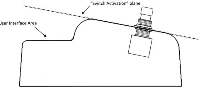
The final option is to put the switch in a separate plane from the user interface. While this leaves the knobs open to changes from cabling, it protects from accidental disturbance from
switch use and allows easy access for changing settings manually or in mid playing. This option takes inspiration from the Ibanez Nine Series guitar effects shown in the figure below, and lends itself to helping with the third functional requirement.
3.2.3 Easy Activation
In order to provide easy activation, the switch must be large enough to activate with minimal accuracy and free of any obstructions. The activation pressure of the switch must be low, and the angle of activation must be comfortable. To meet these requirements the largest flat surface of the chassis is devoted entirely to switching. This means that all the user has to do is place their foot on the large, flat portion of the effect, and they will contact the switch.
To further increase ease of use, the switch chosen has an activation pressure of around 8 Newtons (determined by experimentation) which is easily provided by a natural stepping motion. Additionally, the entire switching surface is at angle (optimized by experimentation), allowing the user to activate the switch without needing to lift their heel off the ground. In this case of form-follows-function, the chassis invites the user to step on the switching surface, and discourages stepping on any other portion.
"Switch Activation" plane
User Inter
Figure 1: A cross section of the chassis complete with mounted switch reveal that the user interface area is not in line with the "switch activation" plane preventing accidental disturbance. The operator must
then be intentionally trying to reach the user interface area for settings to be modified.
3.2.4 Circuitry protection
Drawing from the conclusion associated with section 3.3.1, a metal chassis should provide the internal circuitry with adequate protection from external forces as well as contact with the user's foot during normal operation, assuming the material selection and final design promote this. Since many musicians perform publicly, the chassis must be able to protect from environmental factors as well. Moderate protection from dust, moisture, or other contaminants reaching the circuitry will be provided by a fully enclosed (except for audio and power jacks) chassis. Thus it is necessary to provide the chassis with a back plate as well.
Since the effect pedal will likely travel with the musicians to and from performances, practice sessions, or recording facilities, protecting the circuit also consists of properly constraining it such that none of the components are damaged or the wires break loose from repeated strain. It was therefore deemed necessary to incorporate stand-offs into the design of the chassis, providing a flat surface on which to mount the circuit board with screw holes that
coincide with through holes on the board. This decision added a separate design issue: managing the space inside of the chassis.
3.2.5 Size considerations and ease of assembly
The chassis must only be as large as absolutely necessary to house all of the components. Any larger, and the material cost of the chassis increases with no real benefit to end user, and in
a mass production scheme would add considerably to the cost per unit produced, translating into a higher cost to the consumer. Despite this consideration, the chassis must not be so small as to complicate adjusting the user interface, activating the device, or interfere with ease of assembly. Luckily, a lower limit on size is implicitly enacted by the components necessary for constructing an effect pedal. The chassis must house a 9 volt battery, at least two quarter-inch audio jacks, a number of potentiometers and toggle switches, a large footswitch, the circuit board, and wiring. The final dimensions chosen allow for snug, but easily accessible (to both the user and assembly worker) mounting and housing of these components.
3.2.6 Other Design Considerations
Though not exactly functional requirements, there were a number of design
considerations that arose during initial testing. The chassis employs heavily rounded edges because in testing, there were multiple stable equilibriums that would prevent access to the controls should the effect pedal topple during use. Rounding the edges forces the bottom of the chassis to be the only stable equilibrium position and allows for the pedal to be quickly and easily returned to this position by manipulating the pedal with the foot while in use.
The general shape and color of the chassis should be appealing as well. Visual
appearance is part of a commercial product's appeal. A hammer-tone finish was chosen to give the appearance of a rugged product counteracting the soft-look given by the rounded edges, and hiding any surface imperfections left by the manufacturing processes.
3.3
Material Selection and Manufacturing Process Choice
Based on the design considerations relating to functional requirements one and four, the material choice was narrowed to a conductive metal of some sort. The exact type and alloy would depend on the manufacturing process chosen.
The MIT undergraduate curriculum covers machining and sheet-metal forming as ways to work and create prototypes. Since it was the goal of this thesis to focus on methods not explicitly used in the curriculum, casing and forging, amongst others, were left as the top choices for manufacturing. The fact that tolerances could be somewhat loose (within an eighth of an inch), tooling cost is relatively low (1), surface finish was not an important factor (1), it was not shown in practice during the curriculum, and that the facilities exist on-campus led to sand casting ultimately being chosen as the manufacturing method for the chassis.
In order to choose the proper material numerous considerations including strength, ease of machining (for the secondary operations necessary with sand casting), cost, and availability were taken into account. The aluminum alloy 356-T6 was initially chosen for its material
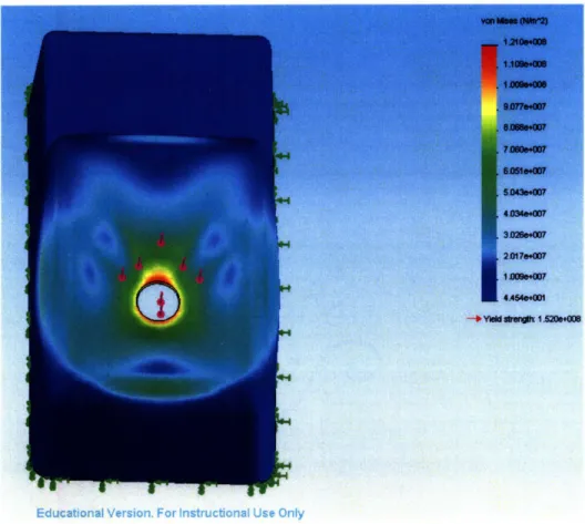
properties, namely the yield strength of 165 MPa, fatigue strength of 60 MPa, and hardness of 70 BHN (2). This translates to an approximate maximal pressure on the switch greater than 1000 N before yielding according to a SolidWorks finite element analysis (FEA) test as shown in the figure below. This is the equivalent of an average male standing on the activation switch alone. With the switch activation force of 8 N, which translates to a stress of less than 25 kPa, fatigue is not even an issue. At a factor of safety of more than 125, this alloy would definitely serve the necessary purpose, and the chassis shell could definitely be made thinner, thus saving material. However, this alloy was not available for casting, so the only aluminum available was
substituted, 153.5. This alloy is nearly pure aluminum, and similar in composition and material properties as the 1060 alloy available in SolidWorks' FEA library.
Educational Version_ For Instructioatn Use Oniy
Figure 2: A screen capture of the FEA analysis run on a solid model of the chassis made from 356-T6 aluminum shows the constraints used, the application of force (1000 N), and an exaggerated deformation pattern. The bottom of the chassis was held as fixed, and the force was applied where the washer on the
threads of the switch would contact the chassis as can be seen in Figure 1 above. Running the identical simulation with a 1060 alloy substituted delivered a much less favorable result. The maximal force on the switch supported before yielding was 220 N, a factor of 5 strength reduction. This means it is possible for the chassis to fail under use should the switch be stepped on with great force, definitely not during normal use, but possibly
accidentally. However, with a fatigue strength of 30 MPa (2), fatigue is still not an issue under normal operating conditions.
In an industry situation, another foundry would be sought and the proper alloy used, but this was not an option, since commercial foundries would not allow students to conduct the casting process. The experience and education associated with completing the casting process was deemed more valuable to the goal of the thesis than using the proper alloy. The process would be the very similar, if not exactly the same, no matter what alloy was used, and the exercise in material selection was not forgone. No real alterations to the mechanics of the thesis were induced by this decision.
3.4 Manufacturing
A specific sequence of steps was adhered to in order to create the chassis. They can best be summarized in the following manner: mold patterns were created and prepared; the patterns were used to create the casting molds; the parts were cast; the secondary operations were performed; and the parts were painted in preparation for integration with the rest of the system. A more detailed description of the process follows.
3.4.1 Creating the Pattern
Using the dimensions dictated by the finite element analysis (mainly chassis shell
thickness), the internal components (internal dimensions), and a four degree draft angle to aid in casting, a solid model of the chassis was designed. This digital format was used to program a Dimension 3D Printer to create patterns from ABS plastic, chosen for its strength to withstand multiple casting sessions. One chassis and two back-plate patterns were created in a cycle that ran for almost 24 hours. The patterns after the cycle was completed can be seen in the
Figure 3: The patterns after a completed build cycle of 24 hours can be seen on the build table inside of the Dimension 3D printer. The white material is the ABS patterns and the brown material is support
material that allows features such as the ones shown on the back-plate to be created. Printing in this orientation provided maximum strength to the alignment tabs on the back-plates and the circuit board
stand-offs in the interior of the chassis.
To remove the support material, the patterns were soaked for another 24 hour period in a heated hydrogen-sulfide solution. Since the layers printed were 0.004 inch thick, the draft angles suffered, however. Instead of smooth sides, the inner and outer vertical surfaces had a step pattern. The patterns were filled with Bondo spot filler and sanded smooth with 220 grit sand paper to eliminate the step pattern and provide smooth surfaces for the draft angles.
3.4.2 Casting Method
Once the patterns were free from voids and smooth enough to be used in casting, they were coated in talcum powder to aid in release from the sand, placed on a flat plate and surrounded by the flask. The sand was then packed into the flask around the patterns to create the cope mold. The cope mold is the side that accepts the molten aluminum. Once packed the
flask containing the cope was turned upside down and the plate removed, revealing the underside of the patterns as seen in the photograph below. The sprue, gate, and runner systems were then cut into the sand.
Figure 4: The flask containing the cope mold, patterns, and sprue is upside-down in preparation for cutting the gate and runner system. Note the chassis pattern is filled with sand. This was done to align
the internal features on the drag with the external features dictated by the cope.
In creating the drag (the bottom mold half that creates the internal features of the chassis), a rather unorthodox technique was employed. After packing a flask entirely with sand and no pattern, the chassis pattern in the cope was coated in talcum powder and packed lightly with sand. This sand was leveled and coated in mold adhesive so that it can be bonded to the drag side of the mold. The two flasks were then mated and turned end-for-end (placing the cope and sprue on top) and separated. The result was the patterns releasing from the cope and pasting the boss for the internal features of the chassis to the drag. The patterns were then removed from the
drag and the two flasks re-mated. After clamping the flasks together, the mold was ready for pouring.
Figure 5: This photograph shows a packed mold mated, clamped, and awaiting molten metal. Note the chassis pattern and mold adhesive in the bottom right.
An induction furnace was used to heat the aluminum pellets in a ceramic crucible to their melting temperature. Safety precautions in handling the aluminum were exercised and the proper metalized heat gear was worn. After pouring, the molds were allowed to cool for 15 minutes and then the products were extracted and water cooled. The following pair of photographs show the pouring process and the final product.
Figure 6: The photograph at the left shows the molten aluminum alloy being poured into the mold's sprue. After solidification and cooling, the molds were broken to reveal the final product (right).
3.4.3 Machining and Secondary Processes
The casting process left products with a poor surface finish, dimensional drift, casting artifacts (such as parting lines) and minor warping. The majority of this was eliminated through secondary processing. Using a mill, the chassis bottoms were levels, the mounting holes for all of the components were drilled, and the circuit board stand-offs were made level. Minor mold deterioration caused some washing effects that had to be cleaned up on the mill. Due to the chassis' irregular geometry, a number of jigs were constructed to hold the castings in place. A significant amount of machining was required to remove the casting artifacts, a fact that would add significantly to the cost of production in a commercial setting.
In addition to machining, the castings were filled with Bondo spot filler in the areas of worst pitting, pinhole-sized cold shuts, and coarsest surface finish. A welding process would have been appropriate if the cold shuts had occurred in a loacbearing area of the chassis. The
entire chassis was then wet-sanded with 150 grit sandpaper to a uniform surface in preparation for painting.
It was determined that the amount of machining and secondary operations necessary for the back-plate would not be worth the time and cost. Therefore, the back-plates were simply cut out of 1/8 inch 6061-T6 aluminum plate in an OMAX water-jet cutting machine in a 2 minute per plate cycle. The screw clearance holes were beveled with a countersink in a drill press. The features intended for the back-plates were abandoned due to the low utility to time/cost ratio. And this manufacturing process proved to be more financially sound. In an industry setting, this part would perhaps have been out-sourced to a company specializing in parts machined via water-jet cutting.
Figure 7: The photograph at the left shows the OMAX water-jet machine cutting back-plates for the chassis. The screw clearance holes are being beveled for use with flat-head screws with a countersink in
the photograph on the right. This process was much more practical than machining the cast back-plates.
3.4.4 Painting
Once the chassis and back-plates were completely machined, de-burred, and sanded, they were moved to a ventilated fume hood for primer coats and painting. Even after secondary processing, the chassis' surface finishes were still less than desirable, so a hammer-tone finish was chosen. This provides a textured finish that gives an appealing look while hiding surface
16 i) Cr ~ Q'CII c~ i-~-~ -: · ·~;-- : C
imperfections. The parts each received two primer coats and two coats of paint. While the 6061-T6 back-plates finished as desired with the textured paint, the 153.5 alloy chassis did not finish as desired. The paint did not texture nearly as much as it did on the back-plate. This may be due to the excessive porosity observed during testing.
Figure 8: Finished chassis and back-plates dry in a fume hood after primer and final paint coats have been applied. The textured finish can be seen most clearly on the back-plates.
3.5 Chassis Testing
With the manufacturing complete, it was necessary to test the chassis for performance and validation of the FEA analysis performed prior to manufacturing. Also the microstructure of a casting sample was examined to determine the quality of casting.
3.5.1 Destructive Testing
A chassis that was cast, yet rejected due to a large cold shut in a non-load bearing area was prepared and used for stress testing. The push-button switch to be used for activation was mounted so that the test loading condition would be as true to practice as possible. After preparing the Instron machine for a compressive test, the test specimen was mounted such that
the flat portion of the switch was parallel to the compressive element on the machine. A photograph of the setup can be seen below.
Figure 9: The setup for applying load to the sample chassis can be seen above. Shims have been used to keep the switch somewhat parallel to the testing mechanism to simulate load application by the user.
Load applied to the switch shaft is transmitted to the nut on the shaft, to the washer, and finally the chassis.
The load - displacement curve (shown below) shows a seemingly unusual pattern, but when combined with the knowledge of what physically occurred, the curve makes perfect sense. The switch is loaded, and the first few data points exhibit the expected linear behavior. At around 360 N, the material in the chassis begins to yield as indicated by the inflection point on the curve at this load. There is a sudden dip at 600 N that coincides with a crack in the material in the switch mounting hole, loosening the hold on the switch. Loading continues and eventually resumes the expected pattern. A second crack in the hole appeared at around 1500 N. The entire surface on which the switch was mounted was severely deformed (due to how soft and ductile the aluminum was) and had strain hardened. At a load of about 1640 N the threads on the switch
shaft began to fail, and the switch slid on the nut until caught by the threads that had yet to fail. Since the entire load was then on one thread at a time, failures happened in quick succession until the switch pushed completely through the chassis leaving the washer and nut behind.
1800 1600 1400 1200 1000 800 600 400 200 0 0 1 2 3 4 5 6 Displacement (mm)
Figure 10: The load-displacement curve for a chassis with a footswitch mounted shows the loads at which the chassis yields, two cracks form around the mounting hole, and the threads on the switch shaft fail. Except for the dip at the 600 N mark, the chassis curve follows the expected pattern for a ductile. Switch
failure occurs at a displacement of about 3.2 mm.
Figure 11: Two cracks around the switch mounting hole, a deep impression from the washer, and the severely deformed switching surface of the chassis can all be seen in the post-test photograph above.
---"----`
The load at yield exhibited by the sample chassis proved to be significantly higher than predicted by the SolidWorks FEA simulation. This is due to small differences in material properties between 153.5 aluminum and the 1060 used in simulation, the fact that the load was not exactly parallel to the switch, and that the washer is not infinitely stiff as it was modeled in the simulation.
3.5.2 Metallurgical Examination
After the chassis was loaded to failure, a sample was taken that contained a crack that had originated in the switch mounting hole and mounted for polishing an etching in a Streurs
ProntoPress-2 at a temperature of 150 C and a force of 29 kN for an 18 minute cycle. The
sample was polished to 0.03 micron surface finish using alumina powder (a polishing compound) and etched with Keller's Reagent for 22 seconds.
Figure 12: The specimen taken from the test chassis is shown above mounted in Bakelite after polishing with alumina powder but before cleaning the powder off. After etching the compound, the microstructure
of the specimen becomes highly visible under magnification. This procedure allows the metallurgist to view a cross section of the specimen and examine the microstructure in the vicinity of the failure in search
of manufacturing or material flaws.
Though no photographs of the microstructure were taken, the high density of porosity was particularly remarkable. Not only were the larger ones able to be seen, but the surface was
riddled with micro-pores. The density was so high that it obscured the view of the
microstructure, whether crack originated in one of these pores or not could not be determined. Despite not answering this question, this examination was useful in assessing the sand casting quality. The high porosity of the aluminum may account for the poor chip formation during machining ("gummy" feeling material) and the sponge-like nature of the material when painted. Even with stress-test numbers surpassing expectation, the metallurgical examination found that the casting quality is very low and would not be acceptable for commercial applications.
4.
KNOBS
4.1 Functional Requirements
The knobs must meet a number of requirements. They are listed below.
1.) The knobs must be small enough to fit in on the user interface area of the effect. 2.) The knobs must fit on the shafts of the potentiometers used in the circuit and remain
securely attached.
3.) The knobs must include an indicator of some sort showing how much of the rotation has been used.
4.) The knobs must be strong enough to resist moderate impact.
5.) The knobs must be comfortable for the user.
4.2
Design Considerations
In order to satisfy the functional requirements a number of design considerations were taken into account. They are not as in-depth as those associated with the chassis, so a section without dedicated subsections will suffice. The user interface area has already been determined by the chassis, so the knobs must conform to this area, while still filling the space out enough such that is does not look empty.
Fitting the shafts is a trivial exercise of measuring the potentiometer shafts, but affixing them poses several possibilities. They can be held via set screws, press-fit, or even glued into place. Set screws allows for slight variations that may be out of the builder's control if the potentiometers are purchased from a third party. Press fits involve tight tolerances, and that increases the cost significantly. Glues work well, but pose a problem if the part ever needs to be replaced or the knob needs to be removed for any other reason.
The knobs should have some way of indicating how much of the rotation travel has been used. There are various ways to accomplish goal as well. The knob may have numbers
indicating the amount of rotation. Along the same lines, the chassis may have numbers or tick-marks with a single indicator on the knob that serves the same purpose, or vice versa. If a single indicator is used on the chassis, the knob may serve as a labeling mechanism as well, bypassing the need for screen printing or any other type of labeling on the chassis.
The material chosen will play a significant role in how impact resistant the knobs are. Since the potentiometers themselves are not meant to take much load, the knobs should not need to either, but accidents happen. It is best to design for the worst case scenario. Following this rationale, a lightweight metal would work nicely or a high strength plastic.
Making the knob comfortable can be accomplished by a number of ways as well. Since the knob is only handled for seconds at a time during use, comfort is important, but not to an unnecessary extreme. Knobs may have rubber outer rings that provide traction and some give to the knob. However this complicates manufacture by requiring another component and
increasing cost. Likewise, ergonomic indents can be placed on the knobs' outer surfaces that do not interfere with the marking mechanism, but this requires an additional operation unless the
knobs are molded. Knurling or texturing of a metal can also provide a convenient or comfortable handling experience while providing maximum impact resistance.
4.3
Material Selection and Manufacturing Process Choice
Plastics and metals are the two materials that would best satisfy the functional requirements based on the design considerations outlined above. In terms of manufacturing processes, injection molding practice was quite heavily covered in the undergraduate curriculum, however metal forming was not. Metal cutting in a lathe is commonplace in the curriculum, but the lathe's capabilities in metal forming were not shown in practice or discussed much in the curriculum. Round stock 606 1-T6 aluminum is readily available, though steel or brass would make excellent choices that would be visually appealing as well. Forming steel would be much more time consuming than brass or aluminum. Brass is much more expensive than the
aluminum. Taking these facts into account, aluminum was chosen as the material for the knobs and a knurling process as the method of manufacture.
As mentioned in the design considerations, labeling can be done directly on the knobs, thus saving a costly screen printing process on the chassis. CNC engraving was going to be necessary for marking the knobs anyway, so adding a little more time to the engraving to eliminate an additional process is an acceptable trade-off.
4.4
Manufacturing
Using 3/4 inch diameter 6061-T6 round stock, the outer diameter was turned down. About 4 inches were taken down to the proper diameter to allow knurling of about 3.5 inches of stock at a time, enough for 4 knobs after facing and material loss to cut-off tools. A center drill/countersink was used to provide a pilot for the lathe's live center tailstock tool. This item is necessary as knurling exerts large amounts of pressure on the stock, causing considerable
With the knurling tool installed, the lathe spindle was slowed to 90 rpm to allow time for the metal forming to take place. The tool was aligned to the stock and then slowly worked from right to left imparting a heavy diamond knurl. The stock and the knurling tool were both flooded with oil to prevent chip build-up that would mar the knurl by becoming imbedded in the
material. To ensure even knurling, the lathe's Z-axis auto-feed control was used.
Figure 13: The knurling process on a piece of 6061 -T6 round stock with the live center attachment to support the cantilevered end of the stock. Both spindle speed and auto-feed rate were taken slowly to allow time for the aluminum to form into the necessary shape. Large amount of oil were used to flood the
interface between the stock and knurling tool to wash away chips and contaminants.
After knurling, the holes for the shaft and clearance of the nut on the potentiometer were machined using the tailstock drill attachment. A cut-off tool was then used to cut each part to length. When all of the parts were done, they were placed in a collet with a mechanical stop to face off the exposed flat surface and break the edges left by knurling. From here they were placed in a special aluminum jawed vice with a milled pocket that allowed the knob to be held
securely without damaging the knurled surface. A HASS CNC mill engraved the label and rotation indicators the surface at a depth of about 0.020 inch to allow for paint to be inserted, highlighting the engraving. The mill was driven by G-code created by MasterCAM, the program in which the engravings and markings were drawn.
Figure 14: The knurled knob blank being engraved in a HASS CNC mill. Note the aluminum jaws holding the knob blank in place. This was by milling a pocket into the jaws to allow a firm hold without
damaging the knurled surface.
A manual mill was then used to drill the proper hole for a 4-40 set screw. Using a stop made drilling the holes quick since edgefinding and set-up was only necessary for the first knob. The holes were tapped by hand.
To remove cutting oil, the knobs were bathed in an alcohol and water solution. Then gold acrylic paint was inserted into the engravings and allowed to dry. Any overspill was removed by rubbing the engraved surface with an abrasive pad after the paid had dried.
Figure 15: Completed knobs await installation on the final product.
5. Circuitry
While circuit design and circuit building are not part of the mechanical engineering curriculum, electronics are introduced in various classes. A well versed engineer should be familiar with other disciplines, so while no real circuit design was done in this thesis, the circuit was modified. The circuit board layout was entirely original, and its manufacture was
outsourced to a printed circuit board (PCB) manufacturing company.
5.
1 Circuit Choice
Integral to the functionality of a guitar effect is the circuit. While the external
components are what the user typically sees and associated with the effect's sound, the circuit is where the true tonal shaping takes place. The chassis and user interface need only be designed once, but many different circuits can be housed in the same model of chassis.
The particular circuit chosen for this effect has an interesting name and an interesting history. The circuit is called the "Fuzz Face" due to its characteristic "fuzzy" guitar sound and the fact that the original chassis resembled a face. This particular circuit was chosen for a variety of reasons. First, its sound is synonymous with a typical electric guitar sound because of its integral part in many famous guitarists' sounds. It has been said that this circuit "represents the Golden Age of guitar effects" (3). The circuit itself is exceedingly simple, lending itself well to a PCB layout designing exercise. Finally, the circuit was originally designed and patented in 1966 (3), so the circuit is now in the public domain.
5.2 Circuit Details
While the original circuit is considered classic, some modifications were in order. These are best presented with a schematic. The modifications and improvements on the original design will be detailed following a brief description of the schematic.
Input
Figure 16: The updated circuit schematic with additions circled and labeled "A", "B", and "C" respectively.
All areas not circled on the schematic, except for the switch are original to the circuit and have not been modified. Sections A, B, and C were added to the circuit for various reasons.
Section A is a light-emitting diode (LED) circuit that lights the LED as a status indicator. No light means the effect is disengaged, and a lit LED means the effect is engaged. The capacitor serves to delay the current flow, albeit imperceptibly, into the LED so that no audible sounds are created by the change in current draw. The resistors serve to limit the current to the LED to save both the LED and battery life. The LED's current draw can be calculated by Ohm's law to be
less than 1 milliamp, a small increase in current draw (and therefore decrease in battery life) for a useful feature.
Section B is a passive low pass filter whose cutoff frequency can be determined by
1 Eq.l
fcutoff = 2rRC
Wherefcutffis the cutoff frequency, R is the value of the resistor in the filter in ohms, and C is the
value of the capacitor in the filter in farads (4). This filter is in place because the circuit can also be powered externally by a step-down transformer. Transformers normally rely on rectifier circuits that are prone to have rippling in a signal that is supposed to be direct current (DC). The filter in this circuit will attenuate any ripple in the power signal above 5.3 Hz. Considering the original signal to the transformer was oscillating at 120 Hz, the ripple would likely occur at this frequency as well. The filter will likely attenuate all of the ripples, effectively providing the circuit with a DC power signal. The battery signal will pass through the filter unaffected. The diode in section B is intentionally non-conduction in its current state. Should the battery be hooked up incorrectly or the wrong polarity power transformer be used, the diode will conduct and protect the circuit from harm. Otherwise, the diode is "invisible" to the circuit.
Section C is also a low-pass filter that was added to the input of the circuit prior to the original audio input. Substituting the values of the filter into equation 1 above shows that attenuation will occur at frequencies above 159 kHz. This is well above the musical range of a
guitar, but it works well for filtering out any RF interference that the signal may have picked up. Due to the high-gain nature of the effect, any interference or noise is amplified along with the guitar signal in the audio path. It is wise to filter this before it has a chance to be amplified by the rest of the audio circuit.
The remainder of the circuit is part of the original circuit design, and it is outside the scope of this thesis to explain what each of the components in the original design do and how that circuit works.
5.3 Printed Circuit Board Design
By using the program ExpressPCB, designing the circuit board was a matter of setting a border for the dimensions of the board, placing the mounting holes (for mounting to the chassis' stand-offs) and the physical placement of the LED with relation to the mounting holes. From there, the rest of the open space was free to use for components. Following the circuit schematic from one end to the other was a helpful strategy to make sure all components were included in the layout. Only a single jumper was necessary. The program left the option of labeling the board for assisting the assembler in laying the board out correctly. All of the component
positions on the board were labeled with their component number per the schematic shown in the figure above. The circuit board manufacturing was outsourced to ExpressPCB.
Figure 17: A screen capture in the ExpressPCB program shows the final PCB layout design that was sent to the ExpressPCB company for manufacturing. All components and off-board wiring points are labeled
5.
4 Printed Circuit Board Assembly
The circuit boards were assembled by matching the components to the diagram shown in the figure above. After soldering the components in place, the circuit board was moved into the chassis where all of the off-board components (jacks, potentiometers, and switch) had already been mounted and had wires soldered in the appropriate area. The wires from the off-board components were matched to the appropriate spot on the PCB. Since the board is double sided with all of the through holes being conductive on both sides, the potentiometers could be neatly wired to the back side of the board while the switch wires were soldered to the component side.
Figure 18: The completed PCB was assembled with onboard components outside of the chassis. The off-board components were installed to the chassis, then wired to the off-board before securing it to the chassis. The double sided board enabled wiring to be done neatly with relatively short wires. Note the choice of battery power or an external transformer. The transformer jack disconnects the battery from the circuit
whenever a plug is inserted.
6. Final Assembly and Testing
After affixing off-board components to the chassis and installing the battery and circuit board, all that remained was installing the knobs. The knobs were installed by making a small gold dot on the chassis at the 90 degree point of the potentiometer. The potentiometers were
turned fully counter-clockwise, and the knobs' tick marks that indicate minimum travel were then aligned with this dot.
Once fully assembled, the unit was placed between a guitar and amplifier and tested for functionality. The sound produced was as expected, the LED lit up when the effect was
engaged, turning the knobs produced the desired change in sound, and the added filters kept out both RF interference and power signal ripple.
Figure 19: The completed guitar effect pedal being tested. Note the lit white LED indicating the effect is
engaged.
7. Recommendations and Conclusion
7. 1 Mass Production Recommendations
Despite the educational value and the low tooling cost, sand-casting, at least in the method described in this thesis, is not practical for mass production of this chassis. The
man-hours necessary for secondary processes negate any savings in tooling unless automation is used for the secondary processes. Three possible alternatives would be die-casting, sheet metal forming, or plastic injection molding. Die-casting would produce parts that were more dimensionally accurate that require less secondary processing at the expense of high initial tooling costs. Sheet metal forming would produce parts quickly and could be automated.
However, the rounded edges would be sacrificed, thus reducing the ease of returning the effect to its normal position. Plastic injection molding would also produce parts extremely quickly. If a high-strength plastic is used, the chassis will be able to meet the functional requirements set forth earlier. A shielding or conductive paint can be applied to the interior of the chassis to help with grounding and RF interference prevention. Injection molding may prove to be the most
economical method of manufacture, producing chassis with the best performance to cost ratio.
7.2
Assembly Recommendations
To aid in assembly, it is recommended include a solder mask on the circuit board. This would allow automation to place and solder components into place with ease. For any wiring that must be done by hand, the two sided PCB method provides convenience and time saving by not having to remove the board to solder components to it. The footswitch can be mounted on its own circuit board via automation with a ribbon cable connection between the footswitch circuit board and the effect circuit board. This would substantially reduce assembly time, and increase throughput in a commercial situation.
7.3
Conclusion
A functional, though less than ideal, final prototype was successfully produced by focusing on manufacturing methods that were not explicitly practiced in the MIT mechanical undergraduate curriculum. This exercise in design and manufacturing included elements from
the material science and electrical engineering disciplines. Sand casting, metallurgical inspection, and circuit board design were practiced and learned by way of this thesis.
Acknowledgments
The author would like to acknowledge and express gratitude for the help and participation of the following:
Mike Tarkanian, Course 3 Technical Instrutor without whom the casting in this thesis would not have been possible.
Gerry Wentworth and Pat McAtamney of the Laboratory for Manufacturing and Productivity for their great machining advice, technical help, and humor.
Yinlin Xie, Course 3 Technical Director who provided generosity and help with metallurgical examinations during crunch time.
Aaron Buchok for introducing me to the Course 3 technical instructors that have helped in this thesis.
Pierce Hayward, Course 2 Technical Instructor who helped with the stress testing of a sample specimen.
Dick Fenner, Director of the Pappalardo Laboratory for allowing me use of the equipment. Steve Haberek, Technical Instructor at the Pappalardo Laboratory for his advice and help with welding.
Professor Seth Lloyd, Course 2 Professor for supervising the thesis and allowing such a fun project.
Mark Belanger and Matthew "small time" Humbert for their help with rapid prototyping. Instructor Gim Hom and Professor Manos Chaniotakis for their efforts to teach electrical engineering principles to non-electrical engineering students.
Bibliography
1. Kalpakjian, Serope and Schmid, Steven R. Manufacturing Engineering and Technology.
4th Edition. Saddle River : Prentice-Hall, Inc., 2001. 0-201-36131-0.
2. Kaufman, J. Gilbert. Alluminum Alloy Database. [Online Version] s.l. : Knovel, May 11, 2004. http://www.knovel.com/knovel2/Toc.jsp?BookID=844&VerticallD=O.
978-1-59127-671-8.
3. Fox, Darrin. Gizmo Alert: Arbiter Fuzz Face. Guitar Player. September 2000, Vol. 34, 9, p. 111.
4. Rizzoni, Giorgio. Principles and Applications ofElectrical Engineering. 3rd Edition. Boston :