READ THESE TERMS AND CONDITIONS CAREFULLY BEFORE USING THIS WEBSITE.
https://nrc-publications.canada.ca/eng/copyright
Vous avez des questions? Nous pouvons vous aider. Pour communiquer directement avec un auteur, consultez la
première page de la revue dans laquelle son article a été publié afin de trouver ses coordonnées. Si vous n’arrivez pas à les repérer, communiquez avec nous à [email protected].
Questions? Contact the NRC Publications Archive team at
[email protected]. If you wish to email the authors directly, please see the first page of the publication for their contact information.
NRC Publications Archive
Archives des publications du CNRC
This publication could be one of several versions: author’s original, accepted manuscript or the publisher’s version. / La version de cette publication peut être l’une des suivantes : la version prépublication de l’auteur, la version acceptée du manuscrit ou la version de l’éditeur.
Access and use of this website and the material on it are subject to the Terms and Conditions set forth at
Failure modes and mechanisms in gray cast iron pipe
Makar, J. M.; Desnoyers, R.; McDonald, S. E.
https://publications-cnrc.canada.ca/fra/droits
L’accès à ce site Web et l’utilisation de son contenu sont assujettis aux conditions présentées dans le site LISEZ CES CONDITIONS ATTENTIVEMENT AVANT D’UTILISER CE SITE WEB.
NRC Publications Record / Notice d'Archives des publications de CNRC: https://nrc-publications.canada.ca/eng/view/object/?id=916578d5-55d7-4dde-8e8f-b480487bdb1c https://publications-cnrc.canada.ca/fra/voir/objet/?id=916578d5-55d7-4dde-8e8f-b480487bdb1c
Failure modes and mechanisms in gray cast iron pipe
Makar, J.M.; Desnoyers, R.; McDonald, S.E.
A version of this paper is published in / Une version de ce document se trouve dans : Underground Infrastructure Research: Municipal, Industrial and Environmental
Applications, Proceedings, Kitchener, Ontario, June 10-13, 2001, pp. 1-10
www.nrc.ca/irc/ircpubs
1 INTRODUCTION
Gray cast iron is the most common material used in North American water systems, representing about 50% of the total length of installed water mains (Kirmeyer, Richards and Smith, 1994). It is also the material that is most prone to failure. A large water utility may experience 300 or more water main breaks a year. Each such main failure causes dis-ruptions to water supply and may require emergency repairs. If a large diameter main fails, millions of dollars of damage may result. Even without a large main failure, the total cost of small diameter water main breaks represents a significant portion of the annual operating budget of most water utilities.
Despite the economic and social significance of water main breaks, little work has been done to analyse the failures and understand the mechanisms that cause them. Past research has concentrated on soil and corrosion behaviour (Romanoff, 1964; Zamanzadeh, 1990; Fitzgerald, 1968). The work that has been done to investigate the failures them-selves has largely been for legal purposes to deter-mine liability for a particular single water main fail-ure. This has led to a widely held belief that the failure process is a simple one, where a pipe cor-rodes to the point at which it can no longer with-stand the applied internal and external forces, re-sulting in a main break.
However, recent work at the National Research Council Canada (NRC) has shown that the failure process is much more complex than expected. Cor-rosion plays a significant role in gray cast iron water main failures, but soil-pipe interactions, poor pipe casting techniques and human error are also impor-tant factors. Failures also often take place in multi-ple stages, rather than in a single episode. This
pa-per discusses the different modes of failure in gray cast iron pipes and the causes behind those failures. Individual examples of ductile iron failures will also be examined. A number of photographs of pipes are presented in order to assist practitioners in identify-ing similar problems in other water systems. Finally, a case study will be presented that briefly discusses the failure analysis process.
2 FORCES ON IN-SERVICE PIPES
At the most basic level pipe failures are caused by applied forces exceeding the residual strength of the metal. The forces applied to pipes have been inves-tigated in detail elsewhere (Rajani, Zhan and Kuraoka, 1996), but a brief summary will be pre-sented here to provide the context for the remainder of the paper. The forces applied to water pipes can be considered as five groups: those produced by internal water pressure; bending forces; crushing forces; soil movement induced tensile forces; and temperature induced expansive forces. Gray cast iron pipe systems were generally designed to with-stand only internal pressure and crushing forces (AWWA, 1975). The loads that produced the latter forces were assumed in the standards to be due to ground weight or truck loading above the pipe. However, frost loading and expansive clays may also produce similar loads above the pipe. Crushing failures appear to be very uncommon in gray cast iron pipes. None of the eighty four pipe failures in-vestigated by NRC have shown evidence of this type of failure. Many of the same loads can also produce bending in pipes, which is a common failure mode. Additional loading conditions that can produce bending include some forms of soil movement and
Failure Modes and Mechanisms in Gray Cast Iron Pipes
J. M. Makar, R. Desnoyers and S. E. McDonald
Institute for Research in Construction, National Research Council Canada, Ottawa, Ontario, Canada
Presented at Underground Infrastructure Research 2001, Waterloo, Ontario, June 10-13
2000 Government of Canada
ABSTRACT: Failures in cast iron water mains are more complex and diverse than is widely understood in the industry. This paper discusses the modes and causes of pipe failures that have been encountered during a three year investigation by the National Research Council Canada. In addition to corrosion, manufacturing defects, human error and unexpected levels of pipe loading all play a role in the large number of pipe failures that occur each year.
possibly thermal forces due to differences between the temperature of the water in the pipes and the sur-rounding soil. Another possible loading condition that can cause pipe failures is one produced by soil locking to the pipe wall through friction. Soil movements may then produce tension in the pipe, producing simple tensile failures. Finally, leadite, a sulphur based joint sealing compound used in the 1940s and 1950s appears to produce pipe failures due to the difference between its coefficient of ther-mal expansion and that of the metal in the pipes it seals. This mechanism is discussed further in Sec-tion 3.3
3 FAILURE MODES
The term “failure modes” refers to the actual manner in which cast iron pipes fail, rather than the mecha-nism that causes the failure. These modes vary de-pending on the diameter of the pipe. Smaller di-ameter pipes have lower water pressure but also smaller moments of inertia, which makes them more susceptible to longitudinal bending failures. Larger pipes have higher water pressure and higher mo-ments of inertia, producing a tendency to longitudi-nal cracking and shearing at the bell.
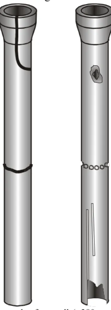
Figure 1. Failure modes for small (<380 mm) diameter pipe. Left pipe: bell splitting at top of pipe, circumferential cracking at middle of pipe. Right pipe: corrosion through-hole at top of pipe, chain created corrosion pitting at middle of pipe, elon-gated corrosion pitting with blow out hole at bottom of pipe. Generally these failure modes will not be seen on the same pipes.
3.1 Blowout holes
As discussed in the following sections, corrosion plays a role in many mechanical failures. However, corrosion by itself or in conjunction with internal water pressure can also cause pipe failures. In this case corrosion pitting occurs until the pipe wall has thinned to the point where the water pressure blows out the remaining, very thin pipe wall. This type of corrosion failure may produce a very small hole or a large one, depending on how localised the corrosion process has been and the pressure experienced by the pipe.
3.2 Circumferential Cracking
Circumferential cracking is the most common failure mode for small diameter (<380 mm diameter) gray cast iron pipes (Figure 1). Typically this type of fail-ure is caused by bending forces applied to the pipe. The resulting failure occurs in a manner similar to a twig snapping, with the failure crack propagating across the circumference of the pipe. This type of failure may also be caused by soil movements pro-ducing tensile forces on the pipe, propro-ducing a simple tensile failure.
3.3 Bell Splitting
This failure mode also appears to be most common in small diameter pipe. Joints in cast iron pipes were originally sealed using rope packed between the bell of one pipe and the spigot of the other. Molten lead was then poured into the joint to complete the seal. Leadite, a rigid, sulphur based compound was used in the 1930s and 1940s as a substitute for lead. However, as a non-metallic compound, leadite has a different thermal co-efficient of expansion than lead. Consequently, very cold temperatures at the pipe can cause the bell to split as shown in Figure 1. This failure mode is different from the longitudinal split-ting shown in Figure 2 both because of different causes and because the crack terminates just below the bell of the pipe once the stresses produced by the thermal expansion have been relieved.
3.4 Longitudinal Cracking
Longitudinal cracking appears to be confined to large diameter pipes. This failure mode may be due to internal water pressure, to crushing forces acting on the pipe or possibly to compressive forces acting along the pipe. Any of these loadings could result in a longitudinal crack. Once the crack has initiated, it may travel the length of the pipe. In some instances cracks have formed on opposite sides of the pipe. The end result has been the removal of a section of the top of the pipe, producing a hole that may be as
long as the pipe and taking up a third of its circum-ference.
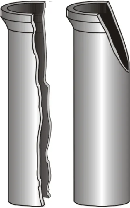
Figure 2. Failure Modes for large (>500 mm) diameter pipe. Left pipe: Longitudinal splitting. Right pipe: Bell shearing. Corrosion pit failure modes are also common on these pipes.
3.5 Bell Shearing
Large diameter pipes generally have too high a mo-ment of inertia to produce the circumferential fail-ures shown in Figure 1. However, large diameter gray cast iron pipes do fail by having a section of the bell shear off as shown in Figure 2. A possible cause of this failure mode is compressive forces pushing the spigot of a pipe into the bell of the next pipe in the pipeline. However, bending forces are more likely to be the cause of this type of failure. Simple compressive loading would tend to produce a crack that propagates down the length of the pipe, but a bending force would produce the type of shearing shown in the figure. An example of this mode was seen in a 1998 failure of a 914 mm diameter main in Boston.
3.6 Spiral Cracking
Some medium (380 mm –500 mm) diameter pipes experience a unique failure mode where the crack in the pipe appears to start in a circumferential fashion and then propagates down the length of the pipe in a spiral fashion. This failure mode has been seen in Des Moines, St. Louis and Ottawa. In the two for-mer cases the failures were associated with pressure surges. The appearance of this failure mode also suggests that the failure is produced by a combina-tion of bending forces and internal pressure.
Figure 3. Spiral failure mode in mid-diameter (380 mm –500 mm) pipe. Corrosion pitting failures have also been seen in these pipes.
4 CAUSES OF FAILURE 4.1 Corrosion
Corrosion induced failures are common to all pipe diameters. Although many of the failure modes de-scribed in section 3 are mechanical in nature, corro-sion pitting is frequently associated with these fail-ures, having produced the weakening in the fabric of the pipe that allowed the failure to occur. As an ex-ample, twenty three out of the twenty five circum-ferential failures investigated by NRC have been as-sociated with corrosion pitting. Other failures are due to corrosion alone (Figure 4). Simple corrosion pitting is a minor failure mode in small diameter pipes, but more important in diameters above about 300 mm.
Investigation of the effects of corrosion on gray cast iron failures in particular is complicated by the presence of two separate but closely related corro-sion processes that may affect the pipes. Simple corrosion pitting can occur in much the same way as steel pipes. However, graphitisation can also take place. This process removes some of the iron in the pipe, but leaves behind a matrix of graphite flakes that is held together in part by iron oxide.
Figure 4. Heavily corroded gray cast iron pipe. (City of To-ronto)
Graphitisation can form a solid substance on the pipe, producing the appearance of an undamaged material. In many cases this corrosion product may also be strong enough to temporarily resist the pipe’s internal water pressure. Cleaning the pipe surface using sand blasting or other methods is frequently the only way to determine the full extent of the cor-rosion damage to the pipe.
Areas of graphitisation are often thought to be composed solely of the graphite flakes. In reality, chemical analysis shows the presence of iron oxide, which appears to be essential for the process. NRC has used high speed corrosion cells on gray cast iron pipe in order to produce artificial corrosion pits. These cells are capable of producing a 5 mm deep, 7 mm wide hole in one to two hours. This corrosion process left behind the graphite in the pipe, but as soft, easily removable carbon flakes, not hard graphitisation. Iron oxide therefore appears to be necessary to form the corrosion product known as graphitisation. In addition, it also suggests that a slow corrosion process is required for the graphite to bond with the iron oxide.
Unlike gray cast iron, ductile iron does not have a matrix of cast iron flakes. Instead, its manufactur-ing process produces fine carbon spheres in the metal. This produces a stronger, more ductile mate-rial than gray cast iron, with the greater ductility giving the alloy its name. The lack of connection between the graphite spheres in this material was as-sumed to mean that graphitisation could not occur.
However, the Water Research Centre in the United Kingdom has observed examples of graphiti-sation in ductile iron pipe (De Rose and Parkinson, 1985). NRC has investigated ductile iron pipe fail-ures from the cities of Ottawa and Toronto where graphitisation was also observed (Figure 5). An elemental analysis of the graphitisation from the Ottawa pipe showed high amounts of carbon, iron and oxygen in approximately the same proportions as seen in graphitisation in gray cast iron pipes. Ad-ditional trace elements from the surrounding soil were also identified. While graphitisation is less common in ductile iron pipes than in gray iron pipes,
it is clearly still a possibility. Visually undamaged ductile iron pipes should not, therefore, necessarily be assumed to be without corrosion damage.
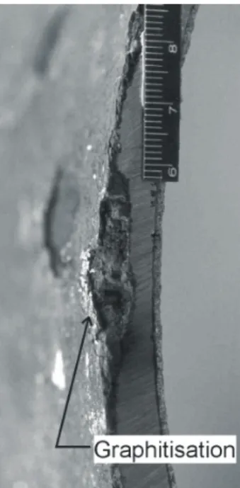
Figure 5. Cross-section of ductile iron pipe showing graphiti-sation. (City of Ottawa)
4.2 Manufacturing Flaws
Gray cast iron pipe was manufactured using a num-ber of different methods, with the two most common being pit casting and spin or centrifugal casting (Talbot, 1926). In the former method a vertical mould was built from sand inside a pit. Molten cast iron was poured into the mould, which then slowly cooled until the pipe could be removed and tested. Spun cast pipe was produced in horizontal, spinning metal or sand moulds, with the former approach re-quiring water cooling of the mould. In this method a ladle entered the centre of the mould and poured molten cast iron down its length while the mould rotated. The spinning of the pipe caused the molten metal to be distributed evenly about the surface of the mould. Centrifugal casting also produced a stronger pipe due to differences in the microstruc-ture produced by the two processes (Makar and Ra-jani, 2000).
Figure 6. Pit cast pipe showing porosity (black dots on cut metal surface). (City of Toronto)
NRC has identified manufacturing flaws in both types of gray cast iron pipe. The more recent ductile iron pipe is also made by spin casting, but none of the ductile iron failures investigated by NRC has been due to manufacturing flaws. Porosity (Figure 6) is the most common manufacturing defect in pit cast pipe. It is produced by air being trapped in the metal as it solidifies. Air in pit cast pipe may have had to travel from the bottom of the pipe to the top to escape, providing much greater opportunities for entrapment than in spun cast gray iron pipe, where the air only needed to reach the inner wall of the pipe surface to escape. However, NRC has found smaller pores than those shown in Figure 6 (2 mm diameter as compared to 8-9 mm) in clusters in poorly manufactured spun cast pipe.
Inclusions are unintentional objects created in metals during manufacturing that are not part of the continuous fabric of the material (Figure 7). They weaken the pipe metal by acting as crack formers, reducing the total cross-section of metal in the pipe and producing stress concentrations. The inclusion shown was formed from iron oxide, but a more common inclusion is undissolved ferrosilicon. The latter material was a common means of adding sili-con to cast iron, which lowers the melting point of the metal and makes it easier to cast. However, if the metal cools too quickly, the ferrosilicon will not completely dissolve, leaving behind a black, spheri-cal inclusion.
Figure 7. Inclusion along a fracture surface. (City of Ottawa)
Spun cast pipes generally appear to have fewer casting defects than pit cast ones. However, they do experience a variety of defects that can only be pro-duced by the spin casting process. Figure 8 shows an example of a longitudinal surface defect. The particular pipe photographed here and in Figures 9 and 10 had numerous examples of this type of defect on its outer surface, which would have been in con-tact with the pipe mould. In some cases these de-fects were detached from the pipe surface as shown in Figure 8, while in others they appeared only as parallel lines on the pipe.
Figure 9 shows a cross-section of the pipe wall across one of these longitudinal flaws. Both the flaw material and the pipe itself are composed of cast iron. However, a noticeable pore is located
di-rectly below the flaw and an iron oxide boundary layer was identified between the flaw and the pipe wall. The presence of the boundary layer and the semi-circular shape of the flaw cross-section sug-gests that the flaw material solidified before the bulk of the pipe. The iron oxide layer was produced by contact with the air as the flaw metal cooled, while the elongated shape and the observed cross-section was produced by a combination of surface tension and the centrifugal “forces” produced by the spin-ning mould.
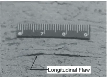
Figure 8. Longitudinal flaw in spun cast pipe. (City of Ottawa)
Figure 9. Cross-section of longitudinal flaw. (City of Ottawa)
The same pipe also had lumps of metal standing proud of the pipe surface (Figure 10). Normally molten metal would be spread out by the spinning process. The presence of the lumps suggests that the pipe metal was cooler than desirable during the casting process, allowing the lumps to solidify in place.
Changes in the pipe wall thickness can also weaken cast iron pipes. Pit cast pipes often have non-uniform thickness around the circumference of the pipe due to the inner sand core of the mould used to make the pipe being off-centre from the outer mould. These differences can be quite large, with a variation from 8 mm thickness at one side of the pipe to 14 mm at the other. Spun cast pipes do not
experience this type of problem due to the nature of the casting process, which evenly distributes the molten metal around the pipe wall. However the pipe shown in Figures 7 to 10 also had a wall thick-ness that varied along the length of pipe, changing from 18 mm to 15 mm over a 2 m distance. This amount of change was significant since the maxi-mum operating pressure allowed for the pipe under the applicable standards could be significantly less for the thinner walled pipe. This latter type of manufacturing defect could only be produced by a reduction in the amount of metal per second flowing onto the pipe mould.
Figure 10. Lumps of metal on pipe surface. (City of Ottawa)
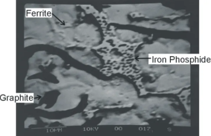
A final type of manufacturing flaw observed in a number of cast iron pipes is the presence of iron phosphide networks throughout the pipe metal (Figure 11). Phosphorus was added to molten cast iron in order to lower the melting point of the metal and its viscosity. This meant that lower casting temperatures could be used, reducing the total cost
Figure 11. Portion of iron phosphide network within pipe metal. (City of Moncton)
of manufacture. However, the presence of phospho-rus can also produce the type of network shown in Figure 11. This iron phosphide compound is even more brittle than gray cast iron and its presence weakens the pipe. Most modern steel and cast iron manufacturing attempts to minimise the phosphorus content, with specifications calling for a value that depends on the quality of the steel but is typically
below 0.1 percent by weight (wt%) and often below 0.03 wt%. Gray cast iron pipes may have phospho-rus contents as high as 0.9 wt% and are often in the range of 0.4-0.6 wt.%
4.3 Excessive Forces
Most observed pipe failures are due to a combina-tion of some form of damage or manufacturing flaw and applied forces from the pipe’s environment. However, it is also possible for pipes to fail without the presence of either corrosion pitting or a manu-facturing flaw at the point of failure. In some cases damage elsewhere along the pipe may contribute to the failure. An example of this happening would be where the pipe has failed in tension due to ground movement forces being transferred to the pipe by corrosion pitting. In other cases the applied forces may cause the pipe to fail even without any previous damage to the pipe.
These failures may be particularly perplexing to the practitioner, since they have no apparent cause. In addition, this type of failure has sometimes been observed where there has been no apparent addi-tional loading to the system (i.e. no truck loads, frost loads, changes in temperature or changes in water pressure that might have affected the pipe and caused the failure). Such an event may result in re-placement of the failed pipe and little further analy-sis.
However, there is always a cause for pipe fail-ures. If no defects or corrosion pits are found on the failed pipe, the most likely cause is that the forces applied to the pipe have exceeded its resistance ca-pacity. These forces may have built up gradually over time and be difficult to detect, but their size and direction can be determined by the nature of the failure mode observed in the pipe. They are often produced by ground movements and may have originated at a significant distance from the failed pipe. Failure may occur at a change in pipeline di-rection at a thrust block, for instance, when the ground movement that caused the applied forces happened farther away along the line.
A major question related to this type of failure is whether the forces on the pipeline were relieved by the failure and the subsequent replacement process. If they were not, the pipeline should be assumed to be at a higher than normal risk of further failures. Further research is required to determine the best way of making this assessment. One part of the pro-cess is the establishment of the forces that were likely to be responsible for the failure itself. This determination will require investigating the failure mode, the mechanical strength of the pipe and also the manner in which the pipeline was designed. In some cases the resistance capacity of the line may have been overestimated by mistakes in the
assump-tions made about ground cover, maximum truck loads or maximum water pressure experienced by line. It is also possible that installation procedures that are now recognised as incorrect were used on early pipelines. An example of the latter problem was the use of wooden blocks under the pipe to raise it above the floor of the trench. This approach was later recognised to contribute to pipe failures due to forces being concentrated on the pipe at the blocks, rather than distributed along the length and width of the pipe by the bedding material. It is important to recognise, however, that failures due to excessive forces can also take place even when there are no er-rors in the design and installation of the pipeline.
4.4 Human error
Design problems are one type of human error that can contribute to pipeline failures. However, there are other practices during construction and after that can also promote or cause pipe failures. In particu-lar, some types of corrosion induced failures have been identified as being due to poor installation or movement techniques. Figure 12 shows an example of a pipe that failed due to a large blow out of the side of the pipe. This pipe had a pair of very long corrosion pits that appear to have formed where the black coating on the pipe was scratched during in-stallation. Some additional scratches could also be seen on the pipe. The coating is also seen on ductile iron pipe and is a natural iron oxide byproduct of the manufacturing process that provides some corrosion protection to the pipe. Both spun cast gray
Figure 12. Elongated corrosion pits caused by scratching pipe. (City of Ottawa)
iron and ductile iron pipes have been observed to corrode without noticeable coating damage, but damage to the coating enhances the probability of significant corrosion in the damaged area. In the case shown in the figure, the long thin pits corroded to the point where the metal was paper thin at the bottom of the pit. A pressure surge caused the pipe to fracture along the pit, followed by a full blow out. Similar damage has been observed on ductile iron pipes from the City of Toronto. In this case an un-padded chain was placed around the pipe when it was being moved. Each link of the chain damaged
the pipe coating, resulting in a series of corrosion pits located around the circumference of the pipe (see Figure 1 for a sketch of this failure).
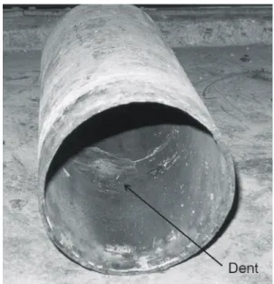
Another common source of failures due to human error is third party damage. Excavations made on or near pipelines without accurate knowledge of their location frequently causes pipeline damage or failure (Figure 13). This type of failure is common to all buried utilities, including both pipelines and other services such as telephone and television cabling.
Figure 13. Dent and hole in ductile iron pipe due to third party damage. (City of Toronto)
Sometimes problems can be perpetuated through simply following a water utility’s standard operating procedures. Figure 14 shows two pieces of a single pipe that experienced four distinct failures in the length shown. The back of the left pipe section was connected to the front of the right one by the clamp that is shown in the picture. Each of the failures was associated with corrosion pitting. These failures ap-pear to have taken place over a significant length of time, with the response to the first three cases being to place a stainless steel clamp over the damaged area. The pipe was not removed until the very long corrosion pit on the left section developed.
An examination of the damage to the pipe makes it clear that it was located in a very corrosive envi-ronment. The stainless steel clamps held the pipe together, but did not prevent further corrosion in a nearby location. In fact, a number of pipe failures observed by NRC occurred next to previous failures covered by stainless steel clamps. It is possible that some aspect of the repair procedure itself may be re-sponsible for the subsequent failures. More research is required to investigate this possibility.
This result suggests that alternate approaches to simple clamping for dealing with corrosion related failures may be desirable. One method used by some cities is to add a sacrificial anode to the pipe at the site of each failure. This should protect the pipe for the duration of the anode’s life. The anodes can
also be checked and replaced if necessary on a scheduled basis, rather than through emergency re-pairs.
Figure 14. Multiple failures on same pipe. (City of Toronto)
5 MULTIPLE EVENT FAILURES
Until recently, most mechanical failures of gray cast iron pipe were assumed to have occurred in a single event, with the pipe cracking to the point of failure due to one incident of applied forces exceeding the strength of the pipe material. Recent work at NRC has shown that many circumferential and bell split type failures occur as a series of multiple events (Makar, 2000). In these cases the pipe cracks part way through and may start leaking water. If the damage is not detected, a second or even third cracking event may take place, with the process continuing until the pipe fails completely or is re-moved from service due to a leak detection cam-paign.
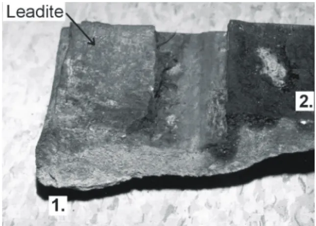
Figures 15 and 16 show two examples of multiple event failures. Their role in a pipe failure can be detected by carefully examining the fracture surface of the pipe. In the case of the pipe shown in Figure 16, only about 80% of the pipe circumference had been cracked through at the time it was removed from service. The intact circumference, labeled as region 3 in the figure, was broken in the laboratory using a stress testing machine. Examination of the entire fracture surface afterwards showed that two cracking episodes had taken place while the pipe was in use. Region 1 was covered with a relatively thick layer of corrosion products that had an orange colour and regions of gray material. The regions la-beled 2 in the figure had a much thinner layer of cor-rosion product with a dark red colour. The gray col-our of the graphite flakes that give gray cast iron its name could also be seen below the corrosion prod-ucts.
Although the pipe in Figure 16 clearly shows that not all circumferential failures require complete cracking around the pipe, visual identification of dif-ferent cracking episodes can be very subjective in nature. Further evidence for this phenomena is pro-vided by elemental analysis of the fracture surface.
Figure 15. Multi-event circumferential failure. “1” indicates the first cracking event, “2” indicates the second cracking event and “3”indicates the region that was intact until broken in the laboratory. (City of Toronto)
Figure 16. Multi-event bell splitting failure. “1” indicates the start of the first cracking event at a small corrosion pit while “2” indicates the start of the second cracking event. (City of Ottawa)
In the case of Figure 16 the visual examination showed evidence of two cracking episodes, with one region near the bell having thick corrosion products and an orange-gray colour and the other region closer to the end of the crack having thin corrosion products with a dark red colour. An elemental analy-sis shows the presence of a number of elements on both regions of the fracture surface that are not pres-ent in the pipe metal. These elempres-ents were therefore acquired from the surrounding soil. However, the region with thicker corrosion products showed the presence of sulphur, aluminum, potassium and a high quantity of calcium, while the region with the thinner layer of corrosion products showed consid-erably smaller amounts of the last three elements and no sulphur at all. This difference indicates that the fracture surface under the thicker layer had been exposed to the surrounding soil for a longer period of time than that under the thinner layer, providing
further evidence for a multi-event cracking process. Elemental analyses have been done for other frac-ture surfaces with similar results.
The cause of the multi-event fractures is unclear. Normally brittle fractures would be expected to propagate quickly across an entire object. More re-search, including both finite element modelling and fracture mechanics studies, will be necessary to completely understand this aspect of cast iron be-haviour.
6 THE BATHGATE MAIN – A CASE STUDY NRC was asked to conduct a failure analysis on a broken 410 mm water main in the summer of 2000 by the Regional Municipality of Ottawa-Carleton (now part of the City of Ottawa). This main had experienced a spiral failure (Figures 3 and 17) and appeared to have failed in a brittle manner. How-ever, the Region’s records showed the pipe as being ductile iron rather than gray cast iron. The unusual failure mode, the uncertainty in the records and the need to determine the vulnerability of the rest of the line led to the need for the failure analysis.
The sample delivered by the Region to NRC con-sisted of only half the failed pipe. In addition, a section of the pipe at the point where the crack likely initiated was missing. These missing sections of pipe meant that the exact cause of the failure could not be determined. However, it was possible to ex-amine the rest of the pipe and determine its quality.
Figure 17. Medium diameter pipe failure. (City of Ottawa)
The first step in the examination was to cut up the pipe and expose the fracture surface. No evidence for a multi-event failure was seen, but the fracture surface did show a change in the direction of the fracture part way through the pipe (Figure 18). This change in the direction of the surface had not been seen in other pipes that had been investigated by NRC.
Subsequent investigation did not identify any sig-nificant areas of corrosion on the fracture surface or on the pipe in general. However, a large number of
manufacturing defects were found. Numerous small pores were seen in the metal of the pipe and along the pipe surfaces. Each of the casting defects shown in Figures 7 to 10 were found on this pipe. As noted earlier, the longitudinal flaws in Figures 8 and 9 oc-curred frequently on the outer pipe surface. This pipe also experienced the change in wall thickness mentioned earlier.
As shown in Figure 9, the microstructure of the pipe was investigated in order to determine the type of pipe. The presence of graphite flakes in the metal, rather than spheres showed that it was gray cast iron. An elemental analysis confirmed that the pipe metal did not have the small amount of magnesium neces-sary to produce ductile iron. The microstructural analysis did show that the type and form of the graphite flakes in the pipe changed part way through the pipe wall. This change was responsible for the change in the fracture surface shown in Figure 18.
The mechanical properties of the pipe were also investigated, with five tensile tests and seven four point bending tests being conducted on samples from the failed pipe. Multiple tests have been found to be necessary due to the high variability of gray cast iron. Some pipes have shown a variation of as much as 100% between the weakest sample and the strongest (Rajani, Makar and McDonald, 2001). In this case the samples were all taken from sections of pipe without manufacturing defects. The tensile tests all showed pipe strengths above the 124 or 145 MPa called for by the two standards (ASA 1953, AWWA 1967) that may have been applicable to the manu-facture of this pipe. However, one of the four point bending tests produced a modulus of rupture signifi-cantly below that allowed by either standard (224 MPa versus 276 MPa or 310 MPa). Six of the seven tests were below the 310 MPa standard.
Figure 18. Change in fracture surface along spiral crack. (City of Ottawa)
A second pipe was removed from the line to act as a control sample for the investigation. It did not show any of the manufacturing defects identified on the failed pipe. The mechanical tests conducted on the control pipe also showed values that were con-sistently above those required by the standards.
The analysis concluded that the failure was due to the manufacturing defects in the pipe. The inherent
resistance of the pipe to bending was marginal at best compared to the values required by the applica-ble standards. The frequency of the observed defects was such that there was a very high likelihood of one occurring at the failure site. The combination of a weak pipe material and an inclusion, longitudinal flaw or cluster of pores lowered the pipe’s resistance capacity to point where the failure occurred.
7 CONCLUSIONS
Cast iron pipe failures are more diverse and complex than is usually appreciated by the water industry. Failure modes include not only corrosion blow outs and circumferential breaks, but also include longitu-dinal cracking, bell splitting, bell shearing and spiral cracking. The causes of failure go beyond corrosion and mechanical loading to include manufacturing defects and a variety of human factors. Many fail-ures also occur as multiple events, rather than as a single cracking episode.
Understanding the nature and causes of pipe fail-ures is important in making decisions about pipeline rehabilitation and replacement. Pipeline failures are normally unexpected and often produce emergen-cies. This is especially the case for medium and large diameter lines, which may supply water to large numbers of people. A water utility’s major goal in resolving such a failure situation is naturally to prevent water damage to the area around the pipe and restore water supply as soon as possible. How-ever, gathering the information and samples neces-sary to complete a failure analysis should be consid-ered a necessary part of the repair process. Conducting an engineering analysis after a major pipeline failure is essential to determining the risk of a subsequent failure on the same line. The complex nature of pipeline failures and the inherent variabil-ity of gray cast iron pipes mean that the information about the pipe and its failure necessary for the engi-neering analysis can only be acquired by the failure analysis process.
ACKNOWLEDGEMENTS
Pipes analysed in this work were provided by the City of To-ronto through the Civil Engineering Department of the Univer-sity of Toronto, by the Regional Municipality of Ottawa-Carleton (now part of the City of Ottawa), and the City of Moncton. The assistance of Professor Jeffrey Packer and Micheal Seica of the University of Toronto in providing access to the City of Toronto pipes is gratefully acknowledged. The elemental analysis in this paper was carried out by Jeffrey Fraser, Ed Quinn and Jim Margeson, all employees of the Na-tional Research Council Canada. Figures 7 to 10 were photo-graphed by Jim Margeson.
REFERENCES
ASA (American Standards Association), 1953. American Standard Specifications for cast-iron pipe centrifugally cast in metal molds, for water or other liquids. A21.6-1953/AWWA C106-53
AWWA (American Water Works Association) (1975). USA Standard for Thickness Design of Cast-Iron Pipe. USAS A21.1-1967/AWWA H1-67, Denver, Colorado.
De Rose, P.J. and Parkinson, R.W., 1985, Corrosion of Ductile Iron Pipe, Report TR241, WRc Engineering, Water Re-search Centre, Swindon, United Kingdom.
Fitzgerald, J. H., 1968, Corrosion as a Primary Cause of Cast-Iron Main Breaks, Journal of the American Water Works Association, vol. 60., no. 8, p.882.
Kirmeyer, G. J.,Richards, W., and Smith, C.D., 1994. An As-sessment of Water Distribution Systems and Associated Research Needs, American Water Works Association Re-search Foundation, Denver, Colorado.
Makar, J.M., 2000, A preliminary analysis of failures in grey cast iron water pipes, Engineering Failure Analysis 7, pp. 43-53.
Makar, J.M. and Rajani, B.B., 2000, Grey Cast Iron Pipe Met-allurgy, Journal of Materials in Civil Engineering, vol. 12, no. 3, pp. 245-253, August.
Rajani, B.B., Zhan, C. and Kuraoka, S., 1996. Pipe-soil inter-action analysis of jointed water mains., Canadian Geotech-nical Journal, Vol. 33, No. 3.
Rajani, B.B., Makar, J.M. and McDonald, S., 2001, The me-chanical properties of grey cast iron mains, to be submitted to the Journal of Construction Materials
Romanoff, M., 1964, Exterior Corrosion of Cast-Iron Pipe, Journal of the American Water Works Association, vol. 56, no. 9, p. 1129.
Talbot, A.N., 1926, Strength Properties of Cast Iron Pipe Made by Different Processes as Found by Tests, Journal of the American Water Works Association, Vol. 16, July, pp.1-44. Zamanzadeh, M., et. al., 1990, Analysis of Failures in Water