Publisher’s version / Version de l'éditeur:
Journal of Materials in Civil Engineering, 12, Aug. 3, pp. 245-253, 2000-08-01
READ THESE TERMS AND CONDITIONS CAREFULLY BEFORE USING THIS WEBSITE.
https://nrc-publications.canada.ca/eng/copyright
Vous avez des questions? Nous pouvons vous aider. Pour communiquer directement avec un auteur, consultez la première page de la revue dans laquelle son article a été publié afin de trouver ses coordonnées. Si vous n’arrivez pas à les repérer, communiquez avec nous à [email protected].
Questions? Contact the NRC Publications Archive team at
[email protected]. If you wish to email the authors directly, please see the first page of the publication for their contact information.
NRC Publications Archive
Archives des publications du CNRC
This publication could be one of several versions: author’s original, accepted manuscript or the publisher’s version. / La version de cette publication peut être l’une des suivantes : la version prépublication de l’auteur, la version acceptée du manuscrit ou la version de l’éditeur.
For the publisher’s version, please access the DOI link below./ Pour consulter la version de l’éditeur, utilisez le lien DOI ci-dessous.
https://doi.org/10.1061/(ASCE)0899-1561(2000)12:3(245)
Access and use of this website and the material on it are subject to the Terms and Conditions set forth at
Gray cast-iron water pipe metallurgy
Makar, J. M.; Rajani, B. B.
https://publications-cnrc.canada.ca/fra/droits
L’accès à ce site Web et l’utilisation de son contenu sont assujettis aux conditions présentées dans le site LISEZ CES CONDITIONS ATTENTIVEMENT AVANT D’UTILISER CE SITE WEB.
NRC Publications Record / Notice d'Archives des publications de CNRC: https://nrc-publications.canada.ca/eng/view/object/?id=56a9ca3c-dc31-47e4-9b00-c0264c850ce9 https://publications-cnrc.canada.ca/fra/voir/objet/?id=56a9ca3c-dc31-47e4-9b00-c0264c850ce9
Gray cast-iron water pipe metallurgy
Makar, J. M.; Rajani, B. B.
A version of this paper is published in / Une version de ce document se trouve dans : Journal of Materials in Civil Engineering, v. 12, no. 3, August 2000, pp. 245-253
www.nrc.ca/irc/ircpubs NRCC-44241
Grey Cast Iron Water Pipe Metallurgy
J. M. Makar* and B. Rajani
Institute for Research in Construction National Research Council
1500 Montreal Road, Ottawa, Ontario K1A OR6 Canada
Abstract:
The results of a metallographic study of grey cast iron water pipes are reported. These
pipes had been installed between 1885 and 1973 in eight different water systems. Each pipe had
been extracted during scheduled maintenance or failure repairs to provide data for a larger study
to produce a methodology for determining the residual life of grey cast iron pipes. This
metallographic study was conducted to determine the causes of variations in the mechanical
properties of these pipes.
Pit cast and spun cast pipes were found to have distinctly different types of graphite
flakes, flake sizes and metallic matrices. These differences were directly responsible for the
variations in the mechanical properties between the two types of pipes, with the larger flake sizes
of the pit cast pipes in particular producing weaker material. Examples of anomalous pipes that
did not have the standard appearance of either type of manufacture were also found and the
reasons for their appearance identified.
The results of the study show that the metallurgy of the pipes may be a major
contributing factor along with external forces such as corrosion or poor installation practices.
Metallographic analysis can therefore assist water utilities in making decisions on repairs,
rehabilitation and replacement.
*
Introduction:
Although grey cast iron pipe is no longer manufactured for use by the water industry,
these pipes are the most common form of piping in service throughout North America
(Kirmeyer, Richards and Smith, 1994). The age of grey cast iron pipes in use in the ground
ranges from more than 120 to less than 30 years old. As a result of the aging of these pipes and
their extensive use, there is considerable interest in understanding how and why they fail. A
complete understanding of the failure process would enable the operators of water systems to
predict pipe breakages and aid in the scheduling of repairs and replacement. Pipe failures are a
complex process that depends on corrosion, applied external forces and pipe metallurgy and
mechanical properties. The external factors causing pipe failures have been described elsewhere
(Rajani, B., Zhan, C. and Kuraoka, S., 1996), as has the typical appearance of those failures
(Makar, 1999a, 1999b). While knowledge of the failure process is still incomplete, it is known
that the metallurgy of these pipes plays an important role in their failure mechanisms. Grey cast
iron is brittle in nature and the types of failures typically encountered by water system operators
(longitudinal breaks, splitting at the bell, circumferential breaks) reflect that brittleness (Makar,
1999b). However, all grey cast irons are not the same. The quality of the pipe depends both its
age and source. In addition, two different manufacturing methods (pit or vertical and centrifugal
or spin casting) were used to make in-service grey cast iron pipes (Cast Iron Pipe Research
Association, 1952).
Previous workers(Allen, 1933, La Que, 1964, Sears, 1968, Jakobs, 1985, De Rose and
Parkinson, 1985) have investigated the metallurgical properties of grey cast iron pipes.
However, the reported results do not appear to describe the pipe metallurgy using ASTM
pipe samples, while other authors (La Que, 1964, Sears, 1968, Jakobs, 1985) compare one form
of grey cast iron pipe to ductile iron piping. Little work has been done to directly compare the
two forms of grey cast iron pipe to each other. One British report(De Rose and Parkinson, 1985)
that does present both forms of grey cast iron pipe in order to compare them to ductile iron pipe
shows photomicrographs of vertical cast iron pipe that do not appear to be typical of those found
in North America.
The work reported here is part of a larger American Water Works Association Research
Foundation/National Research Council Canada project to develop a methodology to estimate the
residual life of grey cast iron pipes. An overall description of the research project is given
elsewhere (Rajani, B. and Makar, J., 1999, Rajani, et. al., 1999). In summary, the research
approach used mechanical testing of pipes from 16 different North American cities in
conjunction with fracture mechanics, corrosion rates and non-destructive examination to develop
an approach to find safety factors for in-service pipes and to predict their expected residual life.
The samples used in the study were exhumed from the ground by each water utility during
scheduled repairs and replacement. It was apparent from the results of the mechanical tests that
distinct differences existed between the mechanical properties of the pit cast and the spun cast
pipes (Rajani, Makar and MacDonald, 2000). Further differences were observed between the
mechanical properties of the majority of the spun cast pipes and those from the City of
Winnipeg. These differences and the lack of a systematic comparison between the two classes of
grey iron pipe based on ASTM standards led to the work described below.
While the results presented here are important for explaining the mechanical behaviour,
they can also be directly applied by water industry professionals in two ways. First, samples
the precise age is impossible to determine, the approximate time period (pit cast versus spun
cast) can readily be found. In general, such sampling should be used in cases where there are
grounds for suspicion that the age attributed to the pipe is incorrect or unknown, such as
anomalously high break rates, missing records and dates of road construction that differ from the
recorded time of pipe installation. Knowing the correct age for the pipes will help the system
operator to determine when rehabilitation or replacement should be scheduled. The second
application is in explaining pipe behaviour that is far outside the expected bounds, especially in
cases where pipes are much weaker than would be expected. Metallurgical examinations can
indicate if the problem is due to the manufacturing of the pipes themselves. This type of
examination therefore provides a means for determining if replacement of an entire section of
pipe installed at the same time is warranted. Examples of both applications will be given below.
Cast Iron Metallurgy
Reviews of the metallurgy of grey cast irons in general can be found in the American
Society for Metals (ASM) Metals Handbook series (American Society for Metals, 1985, 1988,
1990) and in the Iron Castings Handbook (Iron Castings Society, 1981). The manufacture of
grey cast iron pipe is also described in detail in the Cast Iron Pipe Research Association’s
Handbook of Cast Iron Pipe for Water, Gas, Industrial and Sewer Usage (Cast Iron Pipe
Research Association, 1952). The summary below is drawn from those texts.
Both steels and cast irons are composed of iron alloyed with relatively small percentages
by weight of carbon. However, cast irons differ from standard steels by having significantly
higher carbon (C) and silicon (Si) contents. Steel typically has less than 1.2 weight percent (wt.
to 4.5 wt. % C and 1 to 3 wt. % Si. Cast irons also often have higher sulphur (S) and phosphorus
(P) contents, while manganese is an important additive in both metals.
The extra carbon and silicon in cast iron is added primarily to lower the melting point of
the metal. As an example, steel made with 0.86 wt. % C has a melting point of approximately
1470oC while a cast iron alloy with 4.3% C has a melting point of about 1150oC. This difference
and the enhanced fluidity of the metal that accompanies it is enough to make the cast irons easy
to cast into complicated shapes such as pipes and fittings.
Sulphur, by contrast, is an unintentional addition to iron or steel and, especially in more
modern pipes, is either removed or controlled by the addition of manganese. Sulphur without
manganese tends to form brittle iron sulphide at the boundaries of the grains in the metal. This is
more of a problem in steels, where the inclusions will cause cracks during rolling and other
forming, but can also be detrimental to cast irons. When manganese is present manganese
sulphide (MnS) is formed in the centre of the grains as inclusions instead and is relatively
harmless.
Phosphorus, like sulphur, can be detrimental to the performance of steels and cast irons.
It forms brittle iron phosphide (steadite) inclusions at the grain boundaries, but if more than
about 0.5 wt. % phosphorus is present these inclusions can form a continuous, brittle network
through out the metal. However, phosphorus can also have some beneficial effects on cast iron.
It can be deliberately added to the molten metal in order to promote abrasion resistance. It also
increases the fluidity of the molten metal, which means that casting temperatures can be
somewhat lower than might otherwise be required. Modern manufacturing processes ensure that
cast irons and steels have low phosphorus levels, except where special purpose products are
The basic material of cast iron consists of metal and graphite flakes. The size and the
shape of the graphite flakes and the exact type of metal depend on the manufacturing process.
The metal in cast irons can be either ferrite (almost pure iron) or pearlite (alternating bands of
ferrite and iron carbide in a single grain). Very slow cooling tends to produce very large graphite
flakes and ferrite, moderate cooling produces pearlite and somewhat smaller flakes and very
quick cooling produces ferrite and very fine flakes. The tendency to produce pearlite or ferrite is
also affected by the alloying elements in the cast iron. The shape of the graphite flakes is also
affected by the cooling rate and other processing.
The creation of graphite flakes as cast iron cools is unavoidable, but it is also detrimental
to the strength of a pipe. Flat flakes act as natural crack formers, which means that grey cast iron
tends to produce brittle fractures that travel along the flakes (Sun and Wang, 1990). The grey
colour of alloy’s fracture surface that gives it its name is produced by these flakes, not by the
metal grains (American Society for Metals, 1985). Modifying the shape or size of these flakes
can improve the material’s mechanical properties. The most extreme example is ductile iron,
where the addition of small amounts of magnesium causes the graphite to form small spheres
rather than a continuous network of flakes. As a result ductile iron is both stronger and tougher
than grey cast iron while still being readily castable.
The manufacture of cast iron pipes
Many older North American water distribution systems include pipes installed during the
previous century. Two major shifts in the technology of casting iron pipes have occurred since
that time (pit cast grey iron to spun cast grey iron to spun cast ductile iron) and there have
undoubtedly also been many smaller improvements and changes between those shifts. These
(American Water Works Association, 1908, American Standards Association, 1939a, 1939b,
1953 a, 1953b) governing the manufacture of cast iron pipes since the turn of the century. It is
therefore necessary to examine not only the current state of the art, but also past practices, in
order to understand the differences in the mechanical behaviour of cast iron pipes.
The earliest pipes in this study were pit or vertically cast. A series of upright sand molds
were created in a pit, and the molten cast iron was poured into them. When the metal had cooled
sufficiently, the molds were removed and the pipe rolled free, cleaned, inspected and tested (Cast
Iron Pipe Research Association, 1952). The specifications 7C.1-1908 (American Water Works
Association, 1908) and A21.2 (American Standards Association, 1939a) applied to the
manufacture of pit cast pipe, while the recommended practice A21.1 (American Standards
Association, 1939b) applied to its design. Other standards have also been issued over the years,
frequently in the form of updates to the above.
The technology to produce what are known as spun or horizontally cast pipes was
developed in 1914 (Longmuir, P., 1939) and was introduced commercially over the next two
decades. The mold was made of sand or metal, with the outside of the metal molds being cooled
to prevent damage from the molten metal that is poured into them to form the pipe (Cast Iron
Pipe Research Association, 1952). In either case the mold lay horizontally and was spun as the
metal was poured into it, with centrifugal force causing the metal to coat the inside surface of the
mold, rather than pooling in its bottom. The pipes cast in metal molds initially have higher
residual stress levels due to rapid cooling of the metal against the mold walls, but were heat
treated to remove those stresses. It does not appear that heat-treating was used on those pipes
1953a) and A21.8 (American Standards Association, 1953a) and their updates cover the
manufacture of spun cast pipe in metal and sand molds, respectively.
Experimental Details
Eighteen samples were cut from thirteen pipes for this phase of the examination. These
pipes were chosen to represent a range of mechanical properties and geographical regions. A list
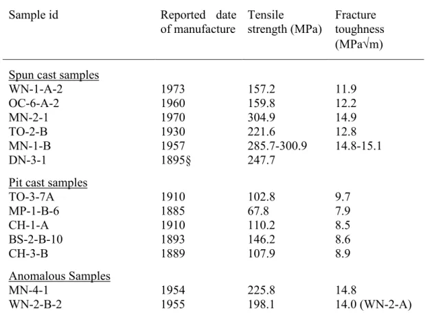
of pipes, their tensile strengths and their fracture toughnesses is given in Table 1. Details of the
test methods and a more extensive discussion of these properties in gray cast iron pipes will be
given in a future paper (Rajani, Makar and McDonald, 2000). Each of the samples was
approximately 10 mm (0.4 in.) long and wide and the same thickness as the pipe. They were
mounted in plastic and polished for examination according to standard metallurgical practice.
The samples were polished and microphotographed so that the type, form and size of the graphite
flakes could be determined according to ASTM standard A247-67 (American Society for Testing
and Materials, 1998a). The samples were then etched to expose grain boundaries and structure
for analysis. The grain size of the samples with more than 50% ferrite was determined at this
time according to ASTM E112-88 (American Society for Testing and Materials, 1998b) . It
should be noted that cast iron samples can be difficult to properly prepare for examination, since
the graphite flakes can be pulled out of the matrix by improper polishing techniques. Different
etchants are also recommended depending on whether the sample is ferritic or pearlitic.
Recommended procedures for preparing cast iron for examination are summarised in the Metals
Handbook Desk Edition(American Society for Metals, 1985).
Metal from each sample was then analysed to determine its chemical composition. The
method of analysis depended on the element that was being measured. Silicon was determined
resulting silica was dehydrated by evaporation with perchloric acid. Silica (plus any impurities)
was filtered and weighed. The silica was then volatilized with hydrofluoric acid and the
impurities weighed, with the silicon determined from the weight difference. Magnesium,
manganese and phosphorus contents were determined by using inductively-coupled plasma
atomic emission spectrometry (ICPAES) following dissolution of the samples with a multiple
acid digestion involving hydrochloric, nitric and perchloric acids. Carbon and sulphur were
determined by combustion analysis using LECO instruments.
The final type of tests used on these samples was Vickers Microhardness measurements.
This test was used instead of the Rockwell B tests called for in the AWWA standards for the
manufacture of cast iron pipe as it allowed multiple tests to be made on the surface of the same
small sample to check the variation in hardness from the inside to the outside of the pipe.
Results and Discussion
The samples have been divided into three groups as a result of the analysis. These include
spun cast samples, pit cast samples and anomalous samples. The former two types have been
identified both by the reported age of burial of the pipes and by common metallurgical
behaviour. The anomalous samples represent pipes that do not appear to fit the typical
characteristics of either group. With the exception of Figure 8, the photomicrographs shown in
this paper are from the centre of the pipes, where the metallurgical behaviour is the most
consistent and easily identifiable.
(a) Graphite flakes
All of the samples examined showed only flake graphite (ASTM form VII) (American
Society for Testing and Materials, 1998a), with the exception of sample WN-1-A2, which may
thin individual flakes. It is typical for grey cast irons and was expected to be observed in these
pipes. If temper graphite is present in sample WN-1-A2 it may indicate that the sample was
given a longer heat treatment after its initial cooling than the other spun cast pipes received
(American Society for Metals, 1985).
While all of the samples showed the same flake form, the type of flakes varied
consistently between spun cast and pit cast pipe. Table 2 shows the standard ASTM flake types,
while Table 3 shows the forms, types and sizes of the flakes in the individual samples. Type D
graphite is the most common form in the spun cast pipes and was consistently found in the
central region of each sample (Figure 1). The majority of the outer and inner surfaces of these
samples also showed type D graphite, although in some cases type A or C was also seen. The
presence of type D graphite generally means that the metal has been rapidly cooled, which is
exactly what would be expected in a spun cast pipe manufactured in a metal mold. Flake sizes in
these pipes range from 4 to 8, but the largest flake sizes are generally on the inside surfaces of
the pipes, where the metal would have cooled the slowest. The central area of the pipe usually
has significantly smaller flake sizes (7 to 8).
In contrast, the pit cast samples did not show any evidence of type D graphite. The
central regions of the pipes are either type A (Figure 2) or type C (Figure 3), while the exterior of
the pipe can be A, B or C. The flake sizes in these pipes are also noticeably larger than those of
the spun cast pipes, ranging from size 3 to 5 according to ASTM A247. The central area of the
pipe has flakes of the same size as the rest of pipe (3 to 4). These flake types and sizes are likely
to have been produced by the slower cooling rates experienced by the pit cast pipes during
An examination of the work done previously in the United Kingdom (de Rose and
Parkinson, 1985) suggests that type B flakes are typical of pit cast grey iron pipes manufactured
in that country. This is clearly not the case in North America, which indicates that there may
have been differences in the manufacturing techniques used in each region.
The clear differences between metallography of the two classes of North American pipes
suggest that this type of metallurgical analysis can provide a relatively simple method of
discriminating between them where records are missing or suspect. An example of its use is for
sample DN-3-1, which was recorded as being from 1894 (Figure 4). This sample has type D
graphite with very small flakes in the pipe center. The appearance of this pipe indicates that it is
really a spun cast pipe and that the records for the pipe may not have been updated when it was
installed. The mechanical properties of this sample also correspond to those that would be
expected from a recent, spun cast pipe.
The other two anomalous samples, MN-4-1 and WN-2-B2, do not clearly fit into either
category of pipe. Both samples are dated to the time period when spun cast grey iron pipes were
manufactured and both pipes show mechanical strengths typical of that period as well. However,
MN-4-1 only shows type D graphite on the outside surface of the pipe (next to the mold),
showing A in the central region and inside surfaces. The flake sizes are also anomalous, being
size 8 on the outside, but sizes 5 to 6 on the inside. The small flake size and type D graphite on
the outside of the pipe suggest that this pipe was cast in a horizontal mold, but the type A
graphite with larger flake sizes indicates that the rest of the pipe metal may not have solidified as
rapidly as the outside region. WN-2-B2 shows very large flakes, but in each region these flakes
(b) Grain structure
Etching the samples to examine the structure of the iron grains showed that the metallic
grains in the spun cast samples (including DN-3-1) were predominantly ferrite, with only
occasional small grains of pearlite. Figure 6 shows a typical example of the etched surface of a
spun cast pipe. The thin black lines between the grey metal are the boundaries of the individual
grains. The etching process widens the apparent size of the graphite flakes in these
microphotographs because the acid used preferentially attacks the graphite.
By contrast, all of the pit cast samples showed significant amounts of pearlite (Figure 7).
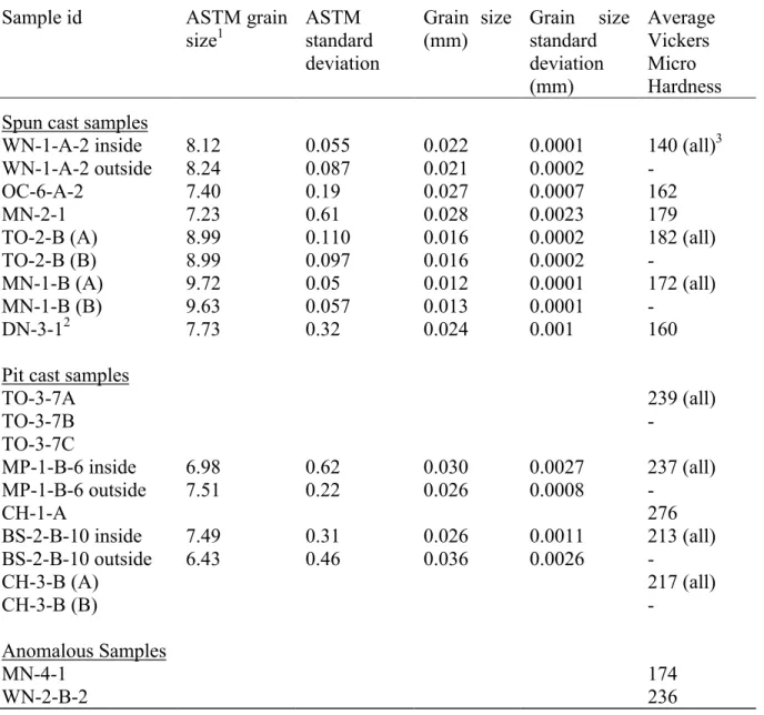
In many cases the pearlite was common enough that the grain sizes in the sample could not be
analysed by the LECO analyser. This instrument relies on the contrast between etched grain
boundaries and the grain itself to measure the grain sizes. If a region of the sample does not have
lower than 50% pearlite, grain size can not be accurately measured. These large amounts of
pearlite are common in many cast irons. Table 4 shows which of the pit cast samples had so
much pearlite that their grain size could not be measured (except WN-2-B2, where the presence
of iron phosphide prevented the measurement). Table 4 also shows the measured grain sizes for
the remaining samples. The grain sizes of the pit cast samples are larger than those of the spun
cast samples, which would be expected since the latter type of pipe was cooled more quickly
during casting than the former, allowing less time for the individual grains to grow in size.
The amount of pearlite and ferrite in an individual sample depends both on the initial
matrix of graphite flakes and the cooling rate of the sample. During the cooling process, carbon
atoms will diffuse through the metal to the graphite flakes. The very fine type D graphite matrix
in spun cast grey iron permits most of the carbon in the surrounding metal to diffuse into the
removed from the metal grains and only ferrite remains. The initial graphite flakes in the pit cast
pipes are both larger and more widely spaced. As a result carbon will diffuse primarily from the
area immediately surrounding the flake, leaving some or all of the more distant grains as pearlite.
This effect is seen in Figure 7. However, if the pipe cools very slowly, the carbon in the grains
will still have time to enter the graphite flakes. The examples of the pit cast iron that have both
bulk pearlite and ferrite present (such as MP-1-B or BS-2-B) are therefore the pipes with slowest
cooling rates.
Cooling rates are also likely responsible for the structure of sample WN-2-B. While
Type A and C graphites are produced by slow cooling rates and type D by very fast cooling
rates, type B flake graphite is produced by an initial quick cooling followed by a rise in
temperature as the molten metal starts to solidify (Loper, 1990). The result is very fine flakes at
the centre of each rosette with the flake size growing towards the outside of the pattern. As is the
case with the pit cast pipes, carbon is removed from the metal matrix into the graphite (Figure 8),
leaving ferrite near the graphite with surrounding regions of pearlite.
An examination of another sample, WN-3-1, from the same city and approximate time
period shows a similar rosette graphite pattern. In addition, the mechanical analysis of the spun
cast pipes from this city11 shows that they in general have a lower tensile strength than pipes
from the other cities that contributed to the project. These observations suggest that the graphite
structure is due to the standard procedures used by the pipe supplier, rather than an error during
the manufacturing of a single pipe. One possible explanation for the metallography of this pipe
is that it was made by spin casting using a sand mold rather than a metal mold.
The etched metallograph of the sample MN-4-1 revealed a different phenomenon. In this
9 shows a scanning electron microscope image at high magnification. Other samples showed
evidence of the presence of iron phosphide, but this was the only sample that showed a network
of the material throughout the sample. The chemical analysis of the pipe metal (Table 5) shows
a high phosphorus content. This percentage of phosphorus (0.62 wt. %) is often present due to
the deliberate addition of the element to the molten metal to improve its fluidity. The high
phosphorus content suggests that the metal in the pipe may not have been raised to as high a
temperature as would normally be the case during the spin casting process, with the phosphorus
being added to compensate for the lower temperature. The presence of the phosphorus is also
likely responsible for the change in the flake type from D to A across the sample towards its
inner surface, since phosphorus is effective in promoting the formation of graphite.
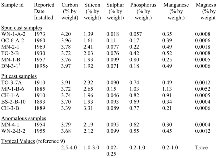
(c) Chemistry
The differences between the pit cast and spun cast samples are not as clear in Table 4 as
they are from the microstructure results. With the exception of the sample CH-3, where the
lowest carbon content of 3.39% is compensated for by the highest silicon content (3.31%), all of
the samples have carbon contents between 3.68 and 4.2 percent by weight. The silicon variation
is somewhat larger (1.39 to 3.31% by weight), but no real difference between the pit cast and
spun cast samples can be seen. The same is also true of the sulphur, magnesium and manganese
content in the samples. One alloying element that does vary more consistently between the two
types of pipe is phosphorus, which is generally below 0.5% by weight for the spun cast pipes and
above 0.6% by weight for pit cast pipes. The exceptions are the anomalous samples, MN-4-1 and
WN-2-A, and one of the spun cast pipes, MN-1. It is noteworthy that MN-1 and MN-4-1, both
pipes from the same city and with similar chemistry and ages, have different microstructures. If
very slight change in chemistry or manufacturing technique may have significant effects on the
microstructure and mechanical properties of a grey cast iron pipe. However, it may be
impossible to determine if this is the case. While records exist of the basic manufacturing
techniques, many municipalities do not have complete historical records of the source of their
pipes. Many local pipe manufacturing companies no longer exist and the ones that do no longer
produce this type of pipe.
(d) Vickers microhardness measurements
The microhardness measurements showed that spun cast samples were noticeably softer
than the pit cast samples. Table 5 gives the average results for the 10 measurements made across
each sample. The difference between the two types of pipe reflects whether ferrite or pearlite is
predominant in each sample. While the presence of graphite flakes caused significant variations
in the hardness measured across each sample, no consistent trends in hardness were seen.
Conclusions
Although a relatively small number of samples were examined, the results indicate that
spun and pit cast pipes can be differentiated by their type of graphite flakes, the size of those
flakes and the metallic matrix of the pipe. Spun cast pipes typically have type D flakes, a ferritic
matrix and small flake sizes (7-8) in the central region. Pit cast pipe typically has C or A type
flakes in the central region, a significant presence of pearlite, and large flake sizes (3-4) in the
central region. Of the three samples originally labelled as anomalous, one, DN-3-1, was
identified as a spun cast pipe that appears to have been incorrectly dated. The two remaining
anomalous samples were both tentatively identified as being spun cast pipes that were produced
There are significant differences between the strengths and fracture toughnesses of pit
cast and spun cast grey iron. These differences are directly attributable to microstructure of the
metal. The carbon flakes in grey cast iron act as crack formers, i.e., where cracks will initiate
when the pipe is placed under stress. The much larger graphite flakes in the pit cast pipe make it
easier for cracks to start and propagate through the metal, reducing the mechanical strength.
Knowing whether the pipe is pit or spun cast can therefore provide a simple initial determination
of its quality.
Metallography can also differentiate between typical and anomalous pipes. In the
examples discussed above, one anomalous sample had excessive phosphorus content and a
network of iron phosphide inclusions, while a second anomalous sample had large B type
graphite flakes, which suggests that the pipe was cooled more slowly than standard spun cast
pipes. The metallurgy of the latter pipe may explain the lower mechanical strengths of the pipes
from the source city. Further work will be necessary to confirm these conclusions.
The examples demonstrate that metallurgical analysis can provide a tool for water
utilities to understand the reasons behind grey cast iron pipe failures in their water distribution
systems. In some cases the metallurgy of the pipes may be a major contributing factor along
with external forces such as corrosion or poor installation practices. This understanding can
therefore lead to better, more economical decisions on scheduling pipe replacement and on pipe
repair and rehabilitation strategies.
Acknowledgements
This research was funded by a joint research project between the American Water Works
Association Research Foundation and the National Research Council Canada. The support of
Chicago, Boston, Moncton, Denver and Minneapolis and the Regional Municipality of
References
Allen, R.M., 1933. Microstructure of Irons in Impact Investigation, Report of Subcommittee XV
on Impact Testing of Committee A-3 on Cast Iron, Proceedings of the American Society on
Testing Materials, vol. 33, part 1.
American Society for Testing and Materials, 1998. Test method for evaluating the microstructure
of graphite in iron castings, ASTM 247-67, vol. 01.02
American Society for Testing and Materials, 1998. Test methods for determining the average
grain size, E112-96, vol. 03.01
American Standards Association, 1939. American Standard Specifications for Pit Cast Pipe for
Water and Other Liquids, A21.2 –1939
American Standards Association, 1939. Manual for the Computation of Strength and Thickness
of Cast Iron Pipe, A21.1.-1939/AWWA C101-39
American Standards Association, 1953. American Standard Specifications for cast-iron pipe
centrifugally cast in metal molds, for water or other liquids. A21.6-1953/AWWA C106-53.
American Standards Association, 1953. American Standard Specifications for cast iron pipe
American Water Works Association, 1908. Standard Specifications for Cast Iron Water Pipe
and Special Castings, 7C.1 –1908
ASM (American Society for Metals), 1985. Metals Handbook, Desk Edition, ASM, Metals
Park, Ohio.
ASM (American Society for Metals), 1988. Metals Handbook, 9th edition, volume 15: Casting,
ASM, Metals Park, Ohio.
ASM (American Society for Metals), 1990. Metals Handbook, 10th edition, volume 1:
Properties and Selection: Irons, Steels and High Performance Alloys, ASM, Metals Park, Ohio
Cast Iron Pipe Research Association. 1952. Handbook of Cast Iron Pipe for Water, Gas, Sewage
and Industrial Services. Chicago, Illinois.
De Rose, P.J. and Parkinson, R.W., 1985. Corrosion of Ductile Iron Pipe, Report TR241, WRc
Engineering, Water Research Centre, Swindon, United Kingdom.
Iron Castings Handbook, 1981. Iron Castings Society, Inc.
Jakobs, J.A., 1985. Underground Corrosion of Water Pipes in Canadian Cities – Case: The City
0SQ81-00096, Canadian Centre for Mineral and Energy Technology, Energy, Mines and
Resources Canada. Canadian Government Publishing Centre, Ottawa, Canada).
Kirmeyer, G. J., W. Richards, and C. D. Smith, 1994. An Assessment of Water Distribution
Systems and Associated Research Needs, American Water Works Association Research
Foundation, Denver, Colorado.
La Que, F. L., 1964. Corrosion Characteristics of Ductile Iron, Journal of American Water
Works Association, vol. 56, no. 11, p. 1433.
Longmuir, P., 1939. Cast Iron Pipe, Charles Griffin and Co Ltd., London.
Loper, Jr., C. R., 1990. Structure and Property Control of Cast Iron, Physical Metallurgy of Cast
Iron IV, Proceedings of the Fourth International Symposium on the Physical Metallurgy of Cast
Iron, Tokyo, Japan, September 4-6, 1989, Materials Research Society, Pittsburgh, Pennsylvania.
Rajani, B., et. al., 1999. Investigation of Grey Cast Iron Mains to Develop a Methodology for
Estimating Service Life, Report to be published by the American Water Works Association
Research Foundation, Denver, Colorado.
Rajani, B., and Makar, J., 1999. A Methodology to Estimate Residual Life of Grey Cast Iron
Rajani, B., Makar, J. and McDonald, S., 2000. Mechanical Properties of Grey Cast Iron Water
Mains, paper to be submitted to the Journal of Construction Materials.
Rajani, B., Zhan, C. and Kuraoka, S., 1996. Pipe-soil interaction analysis for jointed water
mains. Canadian Geotechnical Journal, 33(3): 393-404.
Sears, E.C., 1968. Comparison of the Soil Corrosion Resistance of Ductile Iron Pipe and Gray
Cast Iron Pipe, Materials Protection, pp. 33-36, October.
Sun, G.X. and Wang, Y.M., 1990. The role of Dendrites and Eutectics in the Fracture of Gray
Iron, Physical Metallurgy of Cast Iron IV, Proceedings of the Fourth International Symposium
on the Physical Metallurgy of Cast Iron, Tokyo, Japan, September 4-6, 1989, Materials Research
Sample id Reported date of manufacture Tensile strength (MPa) Fracture toughness (MPa√m) Spun cast samples
WN-1-A-2 1973 157.2 11.9 OC-6-A-2 1960 159.8 12.2 MN-2-1 1970 304.9 14.9 TO-2-B 1930 221.6 12.8 MN-1-B 1957 285.7-300.9 14.8-15.1 DN-3-1 1895§ 247.7
Pit cast samples
TO-3-7A 1910 102.8 9.7 MP-1-B-6 1885 67.8 7.9 CH-1-A 1910 110.2 8.5 BS-2-B-10 1893 146.2 8.6 CH-3-B 1889 107.9 8.9 Anomalous Samples MN-4-1 1954 225.8 14.8 WN-2-B-2 1955 198.1 14.0 (WN-2-A) 1 MPa = 145 psi; 1MPa√m = 0.92 ksi √in; §: date corrected to 1925
WN = Winnipeg, Manitoba, OC = Regional Municipality of Ottawa-Carleton, Ontario, MN= Moncton, New Brunswick, TO = Toronto, Ontario, DN = Denver, Colorado, MP = Minneapolis, Minnesota, CH = Chicago, Illinois, BS = Boston, Massachusetts
Flake type Flake description
Type A Uniformly distributed, apparently randomly oriented flakes Type B Rosette pattern of graphite flakes
Type C Randomly oriented flakes of widely varying sizes
Type D A very fine pattern of flakes surrounding areas without graphite
Type E Graphite flakes have preferred orientation and appear in a quasi-regular pattern
Sample id ASTM graphite flake type1 ASTM graphite form2 ASTM graphite Size3 Inner Edge Centre Outer Edge Inner Edge Centre Outer Edge Inner Edge Centre Outer Edge
Spun cast samples
WN-1-A-2 C C/D - VII VII III 4-5 7-8 7-8 OC-6-A-2 D/A D D VII VII VII 5-6 7-8 7 MN-2-1 D/A D A VII VII VII 6 8 7-8 TO-2-B (A) D D D VII VII VII 6 7 7 TO-2-B (B) D D D VII VII VII 7 7 6 MN-1-B (A) A D D VII VII VII 5 - 7 MN-1-B (B) A D D VII VII VII 5 - 7 Pit cast samples
TO-3-7A A A A VII VII VII 3 3 3
TO-3-7B C C C VII VII VII 4 4 5
TO-3-7C A A C VII VII VII 3-4 4 3-4
MP-1-B-6 B C B VII VII VII 4 4 4
CH-1-A B C B VII VII VII 4-5 3 4
BS-2-B-10 B C B VII VII VII 4 3 5 CH-3-B (A) A A A VII VII VII 3 3 3 CH-3-B (B) A A A VII VII VII 3 3 3 Anomalous Samples
DN-3-1 C/D D D VII VII VII 4/8 8 7 MN-4-1 A A D VII VII VII 5-6 5-6 8
WN-2-B-2 B B B VII VII VII 4 3 5
1
See Table 2 for flake type definitions.
2
In ASTM A247 the flake form refers to the actual shape of the flake, which may be I) spheroidal graphite; II) imperfect spheroidal graphite; III) temper graphite; IV) compact graphite; V) grab graphite; VI) exploded graphite or VII) flake graphite. Pictures of both the flake types and forms can be found in the standard.
3
In ASTM A247 the sizes refer to a range of values as measured at 100x magnification that vary geometrically from 1 mm to 128 mm. Size 3 corresponds to approximately 16-32 mm at this magnification, size 4 to 8-16 mm, size 5 to 4-8 mm, size 6 to 2-4 mm, size 7 to 1-2 mm and size 8 to 0-1 mm.
Sample id ASTM grain size1 ASTM standard deviation Grain size (mm) Grain size standard deviation (mm) Average Vickers Micro Hardness Spun cast samples
WN-1-A-2 inside 8.12 0.055 0.022 0.0001 140 (all)3 WN-1-A-2 outside 8.24 0.087 0.021 0.0002
-OC-6-A-2 7.40 0.19 0.027 0.0007 162 MN-2-1 7.23 0.61 0.028 0.0023 179 TO-2-B (A) 8.99 0.110 0.016 0.0002 182 (all) TO-2-B (B) 8.99 0.097 0.016 0.0002
-MN-1-B (A) 9.72 0.05 0.012 0.0001 172 (all) MN-1-B (B) 9.63 0.057 0.013 0.0001
-DN-3-12 7.73 0.32 0.024 0.001 160
Pit cast samples
TO-3-7A 239 (all) TO-3-7B -TO-3-7C MP-1-B-6 inside 6.98 0.62 0.030 0.0027 237 (all) MP-1-B-6 outside 7.51 0.22 0.026 0.0008 -CH-1-A 276 BS-2-B-10 inside 7.49 0.31 0.026 0.0011 213 (all) BS-2-B-10 outside 6.43 0.46 0.036 0.0026 -CH-3-B (A) 217 (all) CH-3-B (B) -Anomalous Samples MN-4-1 174 WN-2-B-2 236 1
According to ASTM standard E112, on a standard 100x magnification. Note that a smaller ASTM number means a larger grain size. The samples that do not have grain sizes shown had less than 50% ferrite content and could not be measured by the Leco Analyser.
2
Considered to be spun cast pipe after microstructural analysis.
3
Average values labelled “all” include the measurements made for all of the samples checked from the same pipe.
Sample id Reported Date Installed Carbon (% by weight) Silicon (% by weight) Sulphur (% by weight) Phosphorus (% by weight) Manganese (% by weight) Magnesium (% by weight) Spun cast samples
WN-1-A-2 1973 4.20 1.39 0.018 0.057 0.35 0.0008 OC-6-A-2 1960 3.96 1.61 0.11 0.17 0.39 0.0006 MN-2-1 1969 3.78 2.41 0.077 0.22 0.49 0.0018 TO-2-B 1930 3.72 2.03 0.076 0.42 0.52 0.0008 MN-1-B 1957 3.76 1.93 0.099 0.80 0.25 0.0005 DN-3-11 1895§ 3.97 1.92 0.071 0.18 0.49 0.0006 Pit cast samples
TO-3-7A 1910 3.91 2.32 0.090 0.74 0.49 0.0012 MP-1-B-6 1885 3.72 2.65 0.15 1.03 1.13 0.0052 CH-1-A 1910 3.74 1.96 0.046 0.82 0.91 0.0005 BS-2-B-10 1893 3.70 1.93 0.093 0.69 0.34 0.0004 CH-3-B 1889 3.39 3.31 0.089 0.77 0.21 0.0006 Anomalous samples MN-4-1 1954 3.79 2.19 0.095 0.62 0.30 0.0004 WN-2-B-2 1955 3.68 2.12 0.099 0.55 0.45 0.0012 Typical Values (reference 9)
2.5-4.0 1.0-3.0 0.02-0.25
0.2-1.0 0.2-1.0 Trace
1
Considered to be spun cast pipe after microstructural analysis; §: date corrected to 1925 Note: all measurements accurate to four decimal places.
Figures
1. Spun cast sample OC-6-A2 polished to show Type D graphite flake networks (100x magnification).
6. Spun cast sample DN-3-1 etched to show grain boundaries (100x magnification). Black areas are networks of graphite flakes, grey areas, including those within the graphite flake networks, are ferrite. The grain boundaries are the fine lines that divide the ferrite and indicate the edges of individual grains.
7. Pit cast sample TO-3-7 etched to show pearlite (100x magnification). Black areas are graphite flakes, grey areas are pearlite.
Graphite
8. Anomalous sample WN-2-B etched to show pearlite (100x magnification, outside edge of sample). Black areas are etched graphite flakes, light grey areas are ferrite grains and medium grey areas are pearlite grains.
Rosette Graphite
Pearlite Ferrite
9. Scanning electron micrograph of sample MN-4-1. Dark areas are etched graphite flakes, background is ferrite grains, raised “porous” areas are iron phosphide. 2350x magnification
Graphite Ferrite