How to build
safer houses
with confined
masonry
masonry
A guide
for masons
o build s
afer hous
es with conf
ined mas
onry
A gui
de
for
masons
Low-rise buildings in earthquake-prone areas in many parts of the world are often constructed by self-taught masons and contractors. How to build safer
houses with confi ned masonry: a guide for masons is an essential ‘how to’
handbook bringing together a collected knowledge of earthquake-resistant construction techniques indispensable for masons and construction workers. The guide focuses on ‘confi ned masonry’, a construction system consisting of masonry walls (built fi rst) and horizontal and vertical reinforced concrete elements (poured in subsequently) that confi ne the masonry wall panels on all four sides. This method has been developed by practitioners rather than engineers and responds well to the technical and fi nancial capacities of self-builders.
This easy-to-read pocket guide combines detailed illustrations and images with clear instructions to address construction issues. The guide acts as an ideal companion for masons, construction workers, contractors, technicians, architects and students of architecture and civil engineering completing practical training on building sites.
Nadia Carlevaro and Guillaume Roux-Fouillet are architects and the founders
of mobilstudio. They have 10 years of humanitarian experience with the Swiss Agency for Development and Cooperation (SDC) and other organisations in designing and training on earthquake- and cyclone-resilient buildings in Myanmar, Haiti, the Philippines, Nepal and Ecuador. Tom Schacher is an architect with 20 years of humanitarian experience as a technical expert with SDC in Kenya, Rwanda, Turkey, Ethiopia, Iran, Pakistan, Haiti and Ecuador. He has developed manuals and training materials for construction workers on locally appropriate earthquake-resistant construction techniques.
‘ This book warrants wide international dissemination to educate masons and others in the safest way to build houses using the most commonly available construction materials, reinforced concrete and masonry.’
Andrew Charleson, Associate Professor in Building Structures, Victoria University of Wellington
Nadia Carlevaro,
Guillaume Roux-Fouillet
and Tom Schacher
How to build safer houses
with confined masonry
‘This book is a great example of something good emerging from the tragedy of the 2010 Haiti earthquake. The existing reinforced concrete and masonry construction was essentially destroyed. So now, the safe alternative – confined masonry is explained in a way that masons can engage with. In a step-by-step detailed approach readers are instructed in how to build a house in confined masonry.
With its focus upon the practical skills and orientation of its readership almost all the content of the book is conveyed, not through text, but through attractive and well-annotated drawings. Even when communicating technical principles, a simple analogy gets the messages across.
This book warrants wide international dissemination to educate masons and others in the safest way to build houses using the most commonly available construction materials, reinforced concrete and masonry.’
Andrew Charleson, Associate Professor in Building Structures, Victoria University of Wellington
‘This unique guide illustrates construction of low-rise confined masonry buildings in a simple and user-friendly manner, and is expected to be an invaluable resource for house owners and builders of confined masonry houses in earthquake prone regions of the world.’
Dr. Svetlana Brzev, Chair, Confined Masonry Network, Earthquake Engineering Research Institute
How to build safer houses
with confined masonry
A guide for masons
Nadia Carlevaro, Guillaume Roux-Fouillet and Tom Schacher
www.practicalactionpublishing.org
© Swiss Agency for Development and Cooperation, 2018
First published by Swiss Agency for Development and Cooperation and Earthquake Engineering Research Institute 2015
This edition published by Practical Action Publishing 2018
The moral right of the authors to be identified as authors of the work have been asserted under sections 77 and 78 of the Copyright Designs and Patents Act 1988.
This open access book is distributed under a Creative Commons Attribution Non-Commercial Share Alike 4.0 International Licence.
Product or corporate names may be trademarks or registered trademarks, and are used only for identification and explanation without intent to infringe. A catalogue record for this book is available from the British Library.
A catalogue record for this book has been requested from the Library of Congress.
ISBN 978-185339-989-3 paperback ISBN 978-185339-988-6 hardback ISBN 978-178044-988-3 library pdf ISBN 978-178044-989-0 epub
Citation: Carlevaro, N. Roux-Fouillet, G and Schacher, T., (2018) How to build
safer houses with confined masonry: A guide for masons, Rugby, UK: Practical
Action Publishing <http://dx.doi.org/10.3362/9781780449883>
Since 1974, Practical Action Publishing has published and disseminated books and information in support of international development work throughout the world. Practical Action Publishing is a trading name of Practical Action Publish-ing Ltd (Company Reg. No. 1159018), the wholly owned publishPublish-ing company of Practical Action. Practical Action Publishing trades only in support of its parent charity objectives and any profits are covenanted back to Practical Action (Charity Reg. No. 247257, Group VAT Registration No. 880 9924 76). The views and opinions in this publication are those of the author and do not represent those of Practical Action Publishing Ltd or its parent charity Practical Action. Reasonable efforts have been made to publish reliable data and information, but the authors and publisher cannot assume responsibility for the validity of all materials or for the consequences of their use.
Cover photo: A mason at work Cover design: RCO.design
Credit: www.123RF.com Photographer: Patricia Hofmeester - The Netherlands Typeset by vPrompt eServices, India
Printed in the United Kingdom
Contents
Preface x Acknowledgments xi About the authors xii
INTRODUCTION 01 1. THE MASON’S WORLD 03
Masonry tools 1 04
Masonry tools 2 05
Formwork tools 06
Steel reinforcement tools 07
Quality of materials 08
Storage of building materials on site 09
Construction site protection 10
2. CONFINED MASONRY FOR TWO-STOREY
HOUSES 11
Confining elements (ties) 12
A strong house 13
Shape of the house 14
Shear walls 15
Seismic gap 16
Vertical continuity of walls 17
3. FINDING AN ADEQUATE LOCATION 19
Site selection: where to build 20
Flood-related hazards 21
Building on a slope 22
http://dx.doi.org/10.3362/9781780449883.000
Tracing a right angle (3:4:5) 25 Layout 26 5. STONE FOUNDATION 27 Excavation 28 Foundation dimensions 29 Special foundations 30 Stepped foundations 31
Stone masonry construction 32
Reinforced concrete strip footing 33
Curing and ground floor 34
Placing sewage pipes 35
6. REINFORCED CONCRETE TIES 37
Types of steel rebars 38
Stirrups 39
Alternate stirrup positions 40
Stirrup spacing 41
Lap length 42
Tie-beam: T-connection 43
Tie-beam: L-connection 44
Tie-beam to tie-column connection 45
Protection of rebar ends 46
7. FORMWORK 47
Formwork for ties 48
Vertical formwork 49
Horizontal formwork 50
Spacers – 1 51
Spacers – 2 52
8. CONCRETE 53
Concrete mix (1:2:3) 54
Mixing concrete 55
Concrete test 56
Slump test 57
Pouring and compacting concrete 58
Compacting with a vibrating needle 59
Curing the concrete elements 60
Ensure good-quality concrete 61
9. BRICKS AND BLOCKS 63
Which clay bricks to use 64
Brick test 65
Which concrete blocks to use 66
Block test 67
Concrete mix for blocks (1:4:3) 68
Making the blocks 69
10. MASONRY WALLS 71
Cement mortar mix (1:4) 72
Cement–lime mortars 73
Masonry walls height 74
Masonry bonds 75
Toothing 76
Preparing the masonry units 77
Good masonry practice – 1 78
Good masonry practice – 2 79
Placing pipes in walls 80
Door reinforcement 83
Reinforcement of small windows 84
Reinforcement of large windows 85
Horizontal reinforcements (seismic bands) 86
Seismic bands 87
Connections 88
Reinforcement of small windows 89
Reinforcement of large windows 90
Creating shear walls using vertical reinforcements 91
Shear walls with horizontal bands 1 92
Shear walls with horizontal bands 2 93
12. SLAB 95
Placing of slab reinforcement 96
Hollow block slab: formwork 97
Hollow block slab: main reinforcement 98
Hollow block slab: secondary rebars 99
Placing pipes in hollow block slabs 100
Preparing the slab for concrete 101
Pouring the concrete 102
13. LIGHT ROOF 103
Roof shape 104
Gable wall 105
Roof structure – trusses 106
Cyclones 107
Fastening of the veranda framing 108
Fastening of the roof structure 109
Bracing 110
14. RETAINING WALLS 111
Where to build with retaining walls 112
Rule 1 – Wall footing 113
Rule 2 – Slope of the wall (5:1) 114
Rule 3 – Dimensions of the wall 115
Rule 4 – Placing the stones 116
Rule 5 – Through-stones (or bands) 117
Rule 6 – Drainage 118
Retaining wall – Confining elements 119
Gabion retaining walls 1 120
Gabion retaining walls 2 121
15. CONSTRUCTION DRAWINGS 123
Reading plans 124
Reading sections 125
Plan dimensions 126
Section dimensions 127
This guide was originally developed by the Competence Center for Reconstruction of the Swiss Agency for Development and Cooperation (SDC) after the devastating January 2010 Haiti earthquake.
It was developed as a resource for the mason training programme for developing confined masonry construction skills. This training was launched as a response to the urgent need to establish an earthquake-resistant construction practice in Haiti. Its main purpose was to improve workmanship in areas where housing re-construction occurred without technical input.
This guide is regularly used at construction sites and as a resource material for mason training programmes. It offers simple but essential advice on building safer houses using the confined masonry construction technique.
This version of the Guide was adapted by SDC together with members of the Confined Masonry Network of the Earthquake Engineering Research Institute (EERI) for use in various countries and regions of the world.
It is hoped that this resource, originally developed in Haiti, will be useful in other countries facing similar challenges. It is intended for use by local governmental and non-governmental organizations, international humanitarian and development agencies, and most importantly skilled and unskilled masons around the world.
All illustrations are by the authors and by other architects of the Competence Centre for Reconstruction of the Swiss Agency for Development and Cooperation (SDC) in Haiti, Martin Siegrist and Dorothée Hasnas.
We would like to thank those who gave their time and expertise to review this book: Dr Svetlana Brzev and Eng Tim Hart of the Confined Masonry Network (EERI); Marjorie Greene and Maggie Ortiz of EERI; Dr Andrew Charleson of the World Housing Encyclopedia (EERI) and Earthquake Hazard Centre.
ACKNOWLEDGMENTS
Nadia Carlevaro and Guillaume Roux-Fouillet are architects
and the founders of mobilstudio, with a decade of humanitarian experience in designing and training on earthquake and cyclone-resilient buildings in Myanmar, Haiti, the Philippines, Nepal and Ecuador. Both work regularly as construction and planning experts for the Swiss Agency for Development and Cooperation (SDC), the International Federation of the Red Cross and Red Crescent (IFRC) and the United Nations Refugee Agency (UNHCR).
Tom Schacher is an architect working regularly with the
Swiss Agency for Development and Cooperation and has previously developed manuals and training materials for construction workers on locally appropriate earthquake- resistant construction techniques.
INTRODUCTION
How to Build Safer Houses with Confined Masonry is intended
for the training of masons in the technique of confined masonry. It can be used as a guide on construction sites or as a training resource. It is presented in a simple manner and explains in a step-by-step sequence how to build a one or two-storey confined masonry house.
The guide was developed for masons working in countries with very limited financial and technical resources. The recommendations are intended to be conservative (on the safe side) and to ensure the safety of the occupants.
This guide needs to be adapted according to the type and quality of locally available materials and local capacities. The technical recommendations contained in the guide should be in compliance with local construction codes and other regulations (where available).
Illustrations included in the guide may be adapted to suit the local culture and perceptions and to ensure good acceptance. The text may be translated into a local language which the masons are able to read and understand.
While the authors have tried to be as accurate as possible, they cannot be held responsible for construction that might be based on the material presented in this guide. The authors and their organizations disclaim any and all responsibility for the accuracy of any of the material included in the guide.
1. THE MASON‛S WORLD
http://dx.doi.org/10.3362/9781780449883.001
guide book tape measure straight edge level
Masonry tools 1
trowel float hammer chisel club hammer
pencil plumb line string nail chalk line
aluminium screed machete screen (05, 03)
THE MASON‛S WORLD
Masonry tools 2
bucket mixing box cone for
slump test big brush
transparent water
hose 10–20 m pickaxe shovel rammer
grinder needle vibrator
guide book tape measure straight edge level
Formwork tools
crowbar axe saw plane
pencil plumb line string nail hammer chisel
guide book tape measure straight edge level
THE MASON‛S WORLD
Steel reinforcement tools
plastic pipes of hacksaw rebar chain bolt
hammer wire twister
or pincer pliers tin snips chisel
pencil chalk plumb line string nail
Quality of materials
The quality of materials is essential to ensure safe construction
Blocks and bricks: (ch. 9)
minimal size and strength
Water: clean and
not salty
Sand: river sand,
washed and dry Cement: portland cement, new and dry bags
Gravel: crushed or round,
from hard rock and clean, well-graded, max size 18–20 mm
Steel bars: standard size,
ribbed steel, grade 60 new and not corroded
THE MASON‛S WORLD
Storage of building materials
on site
Store cement bags away from the sun and protected from humidity.
Do not place on the ground.
Store wood and steel bars in a dry environment. Do not place on the ground.
Construction site protection
Do not forget that health and security concerns everybody, starting with yourself
If people are injured on a construction site, wash the wound with clean water and soap
and go to a doctor. helmet without helmet without gloves unprotected legs gloves
boots shoes or sandals
long trousers security glasses
YES
NO
2. CONFINED MASONRY FOR
TWO-STOREY HOUSES
http://dx.doi.org/10.3362/9781780449883.002
NO
NO
YES
Confining elements (ties)
Confining the walls is like holding a pile of books together with a string: they
can still move but they will not fall apart.
Horizontal ties (tie-beam) and vertical ties (tie-column).
only tie-beams only tie-columns
CONFINED MASONRY FOR TWO-STOREY HOUSES
A strong house
All walls and openings should be confined to ensure stability during an earthquake.
Confining elements: (chapters 6–8) tie-column and tie-beams
(plinth beam and ring beam)
Anchoring bands and opening reinforcement: (chapter 11)
seismic bands (lintel and sill bands) and vertical reinforcement
max 4.5 m max 4.5 m max 4.5 m max 4.5 m m ax 3 m ring beam lintel band sill band window vertical
reinforcement vertical door
band shear wall plinth beam window vertical band tie-columns tie-beams tie-beams
Shape of the house
Maximum ratio 1:3.
Openings are
too big. Free standing wall without any tie.
3 1
Each facade must have at least one tied wall without openings. These are shear walls.
Shape of the house
CONFINED MASONRY FOR TWO-STOREY HOUSES
YES
YES
NO
Shear walls
Full shear wall
Opening is too big, crossing the diagonals: not a shear wall.
Opening is small and outside the diagonals: it is a shear wall.
Shear walls are walls without windows or with a small window outside of the diagonals of the wall
YES
YES
NO
Seismic gap
Avoid complex shapes by creating seismic gaps. Simple shape: BETTER
Minimum 10 cm (better 45–60 cm)
Complex shape: WORSE
CONFINED MASONRY FOR TWO-STOREY HOUSES
NO
YES
Vertical continuity of walls
Walls must be placed continuously, one on top of the other from ground to the roof.
Cantilevered
The opening
is too large. No vertical continuity
between the upper and lower wall.
3. FINDING AN ADEQUATE
LOCATION
http://dx.doi.org/10.3362/9781780449883.003
Site selection: where to build
Keep enough distance on each side of the house.
YES
Don’t build on embankments. Don’t build on fresh embankments.NO
NO
Don’t build too close to a cliff.
Don’t build on stilts.
NO
NO
Don’t build at the foot of a cliff.NO
Flood-related hazards
Don’t build at the bottom of a canyon.
NO
Don’t build near a river.
NO
Don’t build near the ocean
NO
FINDING AN ADEQUATE LOCATION
Building on a slope
Don’t build against a retaining wall.
NO
Don’t build on top of a retaining wall.
NO
Build between retaining walls.
YES
4. LAYOUT
http://dx.doi.org/10.3362/9781780449883.004
Site preparation
Remove the topsoil and the excavated material, and place it in two (or more) different heaps, away from the excavated area.
Check whether the ground is level by using a transparent hose filled with water.
water level
LAYOUT
Tracing a right angle (3:4:5)
3m 4m 5m 3 4 5 30 cm 40 cm 50 cm 60 cm 80 cm 100 cm 90 cm 120 cm 150 cm 1,5 m 2 m 2,5 m 2,1 m 2,8 m 3,5 m 3 m 4 m 5 m 3 ft 4 ft 5 ft 6 ft 8 ft 10 ft 9 ft 12 ft 15 ft 4 5 4 3 3 3 21 12 1 2
Layout
1m
1m
Place the batter boards 1 m outside the trenches.
batter board nail
marking strings Drive in nails in order to
fix the exact position of the strings. A A' B B' It is a rectangle if:
• each diagonal is of the same length, and if
• the opposite sides measure the same (A=A’, B=B’).
5. STONE FOUNDATION
http://dx.doi.org/10.3362/9781780449883.005
Excavation
Place the soil you have dug up at a minimum of 60 cm away from the trenches,
to avoid its falling back into the excavation.
NO
YES
Minimum 60 cm.
WARNING: dig until you reach firm soil and then build the foundation to the proper width.
He igh t Width 15 cm Foundation height:
hard soil: min 30 cm
rammed soil: min 50 cm
soft soil: min 80 cm
Foundation width:
hard soil: 40 cm
rammed soil: 60 cm
soft soil: 70 cm
STONE FOUNDATION
Foundation dimensions
30 -5 0 c m 10-20 cm topsoil 40 cm Hard soil height: 30-50 cm width: 40 cm 5 cm lean concrete 50 -8 0 c m 10-20 cm 50 cm Rammed soil height: 50-80 cm width: 50 cm strip footing: 50 cm compacted soil 15 cm Soft soil height: min 80 cm width: 50 cm strip footing: 70 cm 10-20 cm m in 8 0 c m Warning!Height above the ground:
Special foundations
If the part above ground is higher than 20 cm, then the foundation acts as a retaining wall.
Do not exceed 40 cm above the ground.
Avoid building in a flood-prone area! The external face of
the foundation wall
must be inclined. house floor
ground level
Foundation height:
rammed soil: min 50 cm
soft soil: min 80 cm
Foundation width:
rammed soil: min 60 cm
soft soil: min 70 cm
30 -4 0 c m 50 -8 0 c m 60-70 cm
STONE FOUNDATION
If you build on a slope, the foundation must be stepped,
keeping the bottom of the trench always horizontal.
Avoid building parallel to the slope!
Stepped foundations
min. 50 cm min. 50 cm min. 50 cm min. 10 cm min. 10 cmStone masonry construction
Do not place the stones vertically.
Place all the stones in a horizontal position.
Place through-stones:
Horizontally: at least every 1 m Vertically: at least every 50 cm
Place through-stones Place through-stones
(view in plan) (view in section)
NO
1 m 1 m
YES
STONE FOUNDATION
Reinforced concrete strip footing
A strip footing is a must for soft soil conditions.
It is also recommended for other soil conditions.
strip footing spacer Strip footing: Width 40 cm = 4 rebars Width 50 cm = 4 rebars Width 70 cm = 5 rebars
Before pouring the concrete, make sure the reinforcement is perfectly vertical. Leave a space around
the reinforcement for the concrete.
60 c m 40 c m 15 c m rebar 12 mm 5 cm 5 cm stirrups 10 mm @ 15 cm spacer
Curing and ground floor
Cure the foundation walls.
Wet every day for the three first days.
Always interrupt foundation work on a sloped line.
Build a ‘drainage pad’ under the floor to block ascending
humidity. foundation wall plinth beam good compacted soil 15-20 cm small stones on top of big stones 7-10 cm lean concrete strip footing flashing drainage pad
STONE FOUNDATION
Placing sewage pipes
The pipe must go through the foundation, under the plinth beam.
plinth beam bigger pipe
smaller pipe foundation
plinth beam
foundation
The pipe must not go through the plinth beam. For tolerance,
leave a hole larger than the sewage pipe,
using a larger diameter pipe. Don’t use empty cement bags.
NO
YES
6. ReinfoRced concRete
ties
http://dx.doi.org/10.3362/9781780449883.006
Types of steel rebars
Use ribbed steel for all rebars.
Smooth bars may only be used for stirrups.
For confined masonry Grade 60 should be used.
Always use standard rebars.
ProducerCountry of origin
Strength indication are written on the rebar. Rebars diameters (imperial and metric):
rebars: min Ø 10 mm better Ø 12 mm stirrups: min Ø 6 mm better Ø 8 mm
Rebar dimensions for vertical and horizontal ties Grade
Diameter
Do not use second-hand rebars.
imperial inch metric
#4 1/2 in. 12 mm
#3 3/8 in. 10 mm
– 1/3 in. 8 mm
#2 1/4 in. 6 mm
no
ReinfoRced concRete ties
Stirrups
Bend stirrup ends at 45°.
Possible stirrup types:
If stirrups are not bent at 45°, they will open during an earthquake. 6 cm (rebar 6 mm) 8 cm (rebar 10 mm)
no
no
Yes
45° 14 20 3 3YES
10 ØYou should alternate position of stirrup hooks.
Alternate stirrup positions
ReinfoRced concRete ties
When using 6 mm stirrups: place them at 15 cm instead of 20 cm, and 7.5 cm instead of 10 cm.
Stirrup spacing
Rules for 8 mm stirrup spacing:1. At the top and bottom of each tie-column and ends of tie-beams place the first stirrup
at 5 cm spacing,
then place stirrups
at 10 cm spacing over a length of H/6 (better 60cm). 2. Place stirrups at 20 cm spacing elsewhere. tie-column @10cm @20cm tie- beam seismic band plinth beam first @5cm first @5cm @2 0c m H /6 ( be tt er 6 0c m ) @1 0c m @2 0c m H
Lap length
The concrete keeps the rebars together like tight fists: the more fists we have (longer overlap)
the stronger the connection.
Lap length:
(overlapping)
50 x Ø
(50 times the diameter) for 10 mm rebar = 50 cm for 12 mm rebar = 60 cm min 50 Ø m in 5 0 Ø
tie wires only hold the rebars in place. They don’t add
strength to the connections!
(lap length) (la p l en gt h)
YES
YES
ReinfoRced concRete ties
Tie-beam: T-connection
Always: extend hooked bars from the inside to the outside.
Connection with
straight bars. Connection around the inner corner.
Lap length:
(overlapping)
50 x Ø
(50 times the diameter) for 10 mm rebar = 50 cm for 12 mm rebar = 60 cm
no
no
50 Ø 50 ØYES
Tie-beam: L-connection
Rebars must cross like the fingers of a hand.
Put an additional rebar around the outer corner.
Hooked bars from inside to inside. Connection with
straight bars.
extend hooked bars from the inside to the outside.
no
no
50 Ø 50 ØYES
ReinfoRced concRete ties
Tie-beam to tie-column connection
At the top of the wall bend the vertical rebars
into the tie-beam.
If you plan to build an upper floor (1st floor) in the future, leave 90 cm in order to create little columns which can be
used to fix guard rails.
one-storey building
90 c
m
90 c
m
Protection of rebar ends
protected rebar ends
Exposed rebars will rust and cannot be reused. Use the little columns to fix guard rails.
Protect rebars with lean concrete.
exposed rebar ends
no
no
YES
YES
7. FORMWORK
http://dx.doi.org/10.3362/9781780449883.007
Formwork for ties
Block walls: Brick walls: Tie = 20x20cm Tie = 20x20cm 20 c m 15 c m m in 1 5 c m m in 1 1 c m Tie = 20x20cm min 15x20cm Tie = 15x20cmSizes of tie-columns and tie-beams:
20 x 20 cm recommended / 15 x 20 cm minimum
20cm wall thickness: place formwork boards on both sides.
15cm wall thickness: Place a 1 inch board under the formwork board.
15-24cm wall thickness: place formwork boards on both sides.
15cm wall thickness: Place a 1 inch board under the formwork board.
FORMWORK
Vertical formwork
Formwork fixed with wires
Attention: with this type of formwork wait until the masonry is solid or the wires will move the bricks.
Horizontal formwork
Use wood planks to connect formwork. Don’t use tie wire. Formwork must be well fastened. Using small planks to keep the formwork apart ensuresmore precision and stability than wires.
Formwork must be well braced.
YES
NO
FORMWORK
Spacers – 1
Spacers are very important: they ensure that the rebars remain in the right place and are well covered by concrete. Don’t use stones to fix the rebars, use spacers instead.
3 cm 3 cm
wire loops
mould for spacers
3 cm 3 cm 3 c m 3 c m
Spacers – 2
Add spacers on all sides
to avoid rebars touching the formwork.
reinforced concrete slab
Alternate the position of the spacers around the stirrups.
joist and pan slab tie-beam tie-column
plinth beam
8. CONCRETE
http://dx.doi.org/10.3362/9781780449883.008
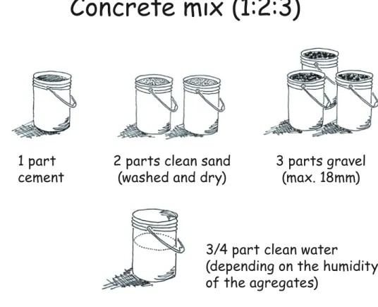
Concrete mix (1:2:3)
1 part cement
Table of various concrete mixes (by volume):
Note:
Concrete with a strength of 210 kg/cm2 corresponds more or less to 350 kg of cement per cubic meter of aggregates.
2 parts clean sand
(washed and dry) 3 parts gravel(max. 18mm)
3/4 part clean water
(depending on the humidity of the agregates)
Cement Sand Gravel Strength
minimum 1 2 4 180 kg/cm2
standard 1 2 3 210 kg/cm2
ideal 1.5 2 3 240 kg/cm2
CONCRETE
Mixing concrete
1. Make a pile with the gravel, the sand and the cement but without water.
2. Mix the pile without water and move it twice with a shovel.
3. Add the water and mix again.
Only add the water at the end.
1. Add half of the water and 1 part of gravel, mix 1 minute. 2. Add the cement and the rest of the agregates.
3. Add rest of the water slowly, mix 3-4 minutes (not more).
Mixing the concrete by hand:
Mixing with a concrete mixer:
Concrete test
QUICK TEST:
Take a handful of concrete. If you can form a nice ball, the concrete is perfect. If the concrete leaks through your fingers, it is too wet.
Concrete must be used in less than 90 minutes. Never ‘refresh’ dried concrete by adding water.
Don’t mix too much concrete at a time.
NO
ball of concrete
YES
CONCRETE
Slump test
SLUMP TEST PROCEDURE:
Use a standard steel cone:
NO
Workability mm Use
low 25-50 foundations with little reinforcement
medium 50-100 for compacted and vibrated concrete
high 100-150 parts with very congested
reinforce-1. Fill cone in 3 equal layers. 2. Tamp down each layer 25 times with a rod (rebar).
3. Lift the cone vertically and place next to the slump. 10 cm 30 c m 20 cm Interpretation of results: more than 15 cm 2.5 - 15 cm
YES
Pouring and compacting concrete
Never add water to make the concrete more liquid and ‘flow down better’.
Roughen up the top
surface of the plinth beam to increase bonding of the mortar for the wall.
Pour the concrete in layers of 30 to 60 cm and compact well with a rod and hammer, or better, with a vibrating needle.
CONCRETE
Compacting with a vibrating needle
By compacting the concrete with a vibrator needle, trapped air will rise to the surface in the form of air bubbles.
1. Insert the vibrating needle 10 cm into the previous layer.
3. Lift the needle slowly (air bubbles rise at a speed of 2.5 to 7.5 cm per second).
4. Don’t touch the reinforcement steel while vibrating.
5. Don’t use the needle to move the concrete sideways.
Advance at regular intervals following the action radius of the needle.
2. Leave the needle for not more than 5 to 15 seconds to avoid the concrete disintegrating.
NO
YES
Curing the concrete elements
Concrete needs water to harden.
After placing concrete, cure the concrete by wetting the formwork three times a day for three days.
Remove formwork only after three days.
After formwork is removed, cure the concrete for
seven days, and cover it with plastic sheets.
CONCRETE
Ensure good-quality concrete
Exposed rebars will rust.
Poor compaction:
the concrete is weakened.
9. BRICKS and BLOCKS
http://dx.doi.org/10.3362/9781780449883.009
Which clay bricks to use
Frog
Best brick:
solid burnt-clay brick with frogs.
Bad brick:
vertical holes more than 50% of surface area.
min 11 cm
(recommended 12.5-15 cm)
note: we recommend using 10MPa bricks.
Vertical holes should be less than 50% of the horizontal surface area.
Solid bricks are better than multiperforated ones.
Bad brick:
with horizontal holes (cannot carry weight). Good brick:
vertical holes less than 50% of surface area.
nO
nO
YES
YES
BRICKS and BLOCKS
Brick test
1. Bricks cannot be easily scratched by a knife.
2. Resists the ‘3 point test’: Person stands on a brick spanning two other bricks.
3. Bricks must give a ringing sound when struck
against each other. 1. regular in form
2. uniform colour 3. not warped
4. no visible flaws or lumps
Visual test: Physical test:
nO
nO
nO
nO
Which concrete blocks to use
Best block: 15-20 cm thick, solid block. Best block: 15-20 cm thick, with 4 holes.Only if excellent quality:
20 cm thick, with 2 holes.
Note: we recommend using 10MPa blocks. Satisfactory block: 18-20 cm thick, with 3 holes. min 15 cm thick recommended 20 cm. web thickness min 25mm voids less than 50%
YES
YES
YES
YES
BRICKS and BLOCKS
Block test
drop five blocks from 1.5 m height on a hard surface (concrete surface).
Acceptable quality:
(less than one broken) Bad quality: don’t buy (if more than one broken)
Blocks that dry in Test blocks before buying them
Check if blocks were cured in the shade.
nO
nO
Stored in the shade: good
YES
YES
YES
Concrete mix for blocks (1:4:3)
+
+
+
3. Add water and
mix again. add water only at the end.
4 parts clean sand 1 part
cement gravel (8-10mm)3 parts clean water3/4 part
1. Make a pile with the gravel, the sand and the cement but without water.
Sand should be crushed, washed and dried. Do not use marine beach sand.
1. Make a pile with the gravel, the sand and the cement but without water.
2. Mix the pile without water and move it twice with a shovel.
BRICKS AND BLOCKS
Making the blocks
Wait eight days before
using the blocks. If possible use a
vibrating machine Fill the molds with the mixture.
To compact the concrete, hit the mold with a shovel and a hammer.
Cure the blocks three times a day for minimum seven days Store the blocks in
To compact the concrete, hit the mold with a shovel and a hammer.
Cover the blocks with plastic sheets immediately.
10. MASONRY WALLS
http://dx.doi.org/10.3362/9781780449883.010
Cement mortar mix (1:4)
+
+
1 part cement Mix the mortar:
4 parts clean sand
(washed and dry) clean water3/4 part
Use 1:3 mix ratio
for 15cm or less wall thickness
1. Make a pile with the sand and the cement but without water.
2. Mix the pile without water and move it twice with a shovel.
3. Add the water and mix again.
Add the water only at the end.
MASONRY WALLS
Cement-lime mortars
Cement-lime mortar
has lower compressive strength than simple cement mortar but offers a better workability, higher elasticity,
and is more economical.
+
+
+
1 part
cement 0.5 part lime
* enough water to get a good workability 4.5 parts
clean sand parts clean about 3/4
water*
Recommended mortar mix proportions:
Cement Lime Sand
1 0.5 4.5
1 1 6
1 2 9
minimum ideal
Masonry walls height
The width of masonry unit defines the wall height. • Bricks: maximum height = 25 x wall width • Blocks: maximum height = 22 x wall width
• Maximum wall height in all cases: 3m
Bricks: H = 2 5 W Blocks: H = 2 2 W H = max. 3 m H W m ax : 2 75 c m m ax 3 00 c m bricks/blocks 15cm / 20 cm / 24 cm bricks 11cm
MASONRY WALLS
Masonry bonds
1/3 to 1/2 of block/brick
Solid wall = running bond – vertical joints are not continous.
Weak wall = stack bond –
NO
YES
Toothing
Distance from blocks or bricks: minimum 3 cm (same length as last joint of thumb).
Toothing:
with bricks 5 cm with blocks 5-10 cm
If toothing is too big, concrete cannot penetrate properly. Also, the weight of the concrete may cause bricks or blocks to break off during the pouring process.
Toothing too big.
NO
MASONRY WALLS
Preparing the masonry units
Soak the blocks in
water for a while... ... water them with a brush before use.
... or ...
... or ...
Good masonry practice – 1
Use a plank as guide to ensure the wall is in plumb and straight.
plinth beam
Place blocks one course at a time
level string
Cure the concrete with water before laying the blocks.
Joints: 10–15 mm = the width of the little finger
Important: fill vertical joints with mortar
MASONRY WALLS
Good masonry practice – 2
100 to 120 cm (5 to 6 blocks)
Don‘t build more than six courses of masonry per day. And then add a seismic band if needed.
plinth beam (tie-beam) foundation
1 course
Protect the wall in warm weather: mortar must not dry out in the sun.
Keep wall moist by pouring water on it three times a day for seven days and/or by covering them with a plastic
Placing pipes in walls
Place pipes in
service duct. in walls or in ties.Don't place pipes Place pipes in
block holes.
NO
YES
Dont break masonry to insert pipes.
Leave a space in the wall for electrical pipes. Once the pipes placed it will be filled with mortar.
The best ways to place pipes is on top of the plaster.
NO
YES
YES
YES
11. SEISMIC
REINFORCEMENTS
http://dx.doi.org/10.3362/9781780449883.011
Vertical reinforcement of openings
There are two types of reinforcements of openings, vertical and horizontal. They are equally valid.
For horizontal reinforcements see p. 86.
Place a vertical reinforcement on each side of every opening.
max 4.5m max 4.5 m m ax 3m max 4.5m max 4.5 m m ax 3m
openings with lintels
openings to the top
Make sure masonry is of excellent quality in walls without openings.
SEISMIC REINFORCEMENTS vertical door band plinth beam door lintel band
Door reinforcement
Hook the door vertical reinforcement rebars and lap 30 cm with the tie-beam rebars, under the stirrups. Do the same
with the lintel band and the vertical bands. tie-beam 30 cm < 90 cm vertical door band plinth beam vertical door band horizontal door reinforcement 30 cm 30 cm 30 c m
Reinforcement of small windows
For windows smaller than 90 cm. tie-beam plinth beam 30 cm vertical window reinforcement 30 cm 30 cm < 90 cm
Hook the window vertical reinforcement and lap 30 cm with the tie-beams reinforcement, into the stirrups.
Do the same with the horizontal reinforcement and the vertical bands.
30 cm
SEISMIC REINFORCEMENTS
Reinforcement of large windows
For windows larger than 90 cm.
90-150 cm window lintel vertical window band 30 cm min 15 cm 30 cm tie-beam window horizontal reinforcement plinth beam window lintel: reinforced seismic band stirrups at 15 cm spacing window vertical band formwork min 15 cm 30 cm
Horizontal reinforcements
(seismic bands)
Place horizontal reinforcements (seismic bands) below and above every opening. Bands should be placed about every 1.2 m.
max 1.2 m max 1.2 m max 1.2 m max 1.2 m max 1.2 m max 4.5 m max 4.5 m max 4.5 m max 4.5 m m ax 3 m m ax 3 m
SEISMIC REINFORCEMENTS
Seismic bands
7.5 - 10 cm Seismic bands: 2 Rebars: 10 mm Stirrups: 6 mm @15 cm use spacersRoughen up the top suface of the bands to increase bonding of the masonry mortar. 15 c m Place stirrups every 15 cm. Place reinforcements
Connections
Hook seismic bands
reinforcement and lap with tie-column reinforcement.
30 cm
50 Ø
Respect overlapping length.
SEISMIC REINFORCEMENTS
Reinforcement of small windows
For windows smaller than 90 cm.
Hook the window reinforcement and lap 30 cm with the seismic band reinforcement, into the stirrups.
vertical window reinforcement 30 cm 30 cm < 90 cm max 1.2m sill band lintel band vertical window reinforcement seismic band 30 cm
Reinforcement of large windows
For windows larger than 90 cm.
90-150 cm lintel height min 15 cm vertical window reinforcement sill band support min 30 cm max 1.2m lintel band 30 cm 30 cm window lintel: reinforced seismic band stirrups at 15 cm spacing vertical window reinforcement formwork seismic band 20-30 cm min 15cm
SEISMIC REINFORCEMENTS
Creating shear walls using
vertical reinforcements
Vertical bands are ‘half tie-columns’ with only two rebars.
max 4.50m Vertical bands: (for openings) Width: 10 cm 2 Rebars: 10 mm Stirrups: 6 mm (@ 15cm)
If a wall between openings is required to act as a shear wall, the vertical reinforcement is identical to a tie-column with
four rebars shea r wall m ax 3m
2 rebars 4 rebars 2 rebars
Shear walls with horizontal
bands 1
In some cases it might seem impossible to provide shear walls in each facade because the owner wants too many windows.
In these cases shear walls are created by increasing the reinforcements on the side of some specific openings. correct, facade
with a shear wall
Reinfocement around openings become tie-columns.
not correct, facades without shear walls
shear walls
SEISMIC REINFORCEMENTS
Shear walls with horizontal
bands 2
The vertical reinforcements of the openings (with 2 rebars) can be made like tie-columns with 4 rebars and extending them down to the plinth and up to the ring beam.
Tie-columns with 4 rebars
Reinforcement of opening with 2 rebars
Reinforcements transformed into tie-columns with 4 rebars
NO
YES
12. SLAB
http://dx.doi.org/10.3362/9781780449883.012
Placing of slab reinforcement
Placement of primary rebars.
Placement of secondary rebars.
Primary rebars are placed in the shorter direction (span).
Step 1
Step 2
Secondary rebars are placed on top of and perpendicular to the primary rebars.
SLAB
max 9 0 c
m
Hollow block slab: formwork
max 75 cm 5 x 10 cm minimum 8 x 10 cm 2 to 2.5 cm thick wood planks or plywood plank counter brace GOOD FORMWORK BAD FORMWORK irregular post
Don't place posts on blocks.
Don't use inclined post
primary rebars Ø 12 mm Ø 10 mm
Ø 12 mm
To ensure a good connection, it is important to insert the hooked slab rebars deep into the bond beam.
primary rebars
block wall bond beam spacer
hook
Hollow block slab:
main reinforcement
NO
YES
secondary rebars spacers
Secondary rebars must be placed in the middle of the concrete covering the hollow blocks with spacers.
SLAB
Hollow block slab:
secondary rebars
NO
secondary rebars Ø 10 mm @ 15 cm hook Ø 12 mmYES
Placing pipes in hollow block slabs
hollow blocks concrete pipe in hollow blocks Drill throughhollow blocks. Pass pipes through the hollow blocks and through concrete only in one spot. Reinforce joist with additional rebars.
Don't drill through concrete. Don't cross concrete all the way.
NO
NO
AVOID
YES
YES
SLAB
Preparing the slab for concrete
Test watertightness of the pipes by filling them with water and wait for four hours.
Pouring the concrete
Compact the concrete with a vibrating needle or, if not available, with a steel rod and hammer. Curing the
concrete: create ponds with sand or mud and fill them with water for a week.
13. LIGHT ROOF
http://dx.doi.org/10.3362/9781780449883.013
Roof shape
Better Better Not so goodAVOID
GoodYES
YES
YES
LIGHT ROOF
Gable wall
Concrete tie on top of the
gable wall.
YES
YES
Roof structure - Trusses
AVOID
YES
Building with planks:
AVOID
(not enough room for nails)
Building with solid timber:
GOOD
Building with plywood gusset:
BETTER! Timber connections:
Put at least
three nails in each direction
Length of nails
should be twice the
thickness of the timber min 3 cm min 6 cm 30 to 40 c m
YES
LIGHT ROOF
Cyclones
Keep verandas independent from main roof: cyclones may
tear off the verandas.
Closed gable wall
NO
NO
Opened gable wall Main roof becoming veranda
If a veranda is part of the main roof,
YES
YES
YES
Fastening of the veranda
framing
bracing
solid fastening plinth < 40 cm
straps
LIGHT ROOF
Fastening of the roof structure
rebar anchors or
straps
Close the spaces between trusses with a plank or a screen to Solidly fasten the
anchors or straps to the wood framing.
Bracing
max. 3.0 m max. 3.0 m max. 4.5 m max. 4.5 m Bracing:wood planks nailed to the trusses
YES
YES
14. RETAINING WALLS
http://dx.doi.org/10.3362/9781780449883.014
Where to build with retaining walls
A retaining wall is not a house wall. Water will and must leak through it.
A retaining wall is meant to hold back the ground.
Don‘t build your house too close to a retaining wall.
Don‘t build your house against a retaining wall. min 0.5 m min. like H H
YES
NO
NO
Don‘t build your house on top of a retaining wall.
RETAINING WALLS
Rule 1 - Wall footing
Height from bottom of wall to firm soil
- hard soil: 30 cm - rammed soil: 30–60 cm - soft soil: 60–90 cm 30 -9 0 c m
NO
YES
1
5
Rule 2 - Slope of the wall (5:1)
Slope 1:5
Every time you go up 5 cm, move back 1 cm Every time you go up 1 meter, move back 20 cm
Chart H : L = 5 : 1 H L H L 100 20 125 25 150 30 175 35 200 40 250 50
NO
YES
RETAINING WALLS
Rule 3 - Dimensions of the wall
Wall base width (D) calculation:
The base of the wall (D) equals the total height (A) divided by 5, plus the top's width (C):
Height above ground (H):
H max = 2.50 m D = A/5 + C Top (C): min 50cm 50 cm: H ≤ 150 cm 55 cm: H > 150 < 250 cm 60 cm: H ≥ 250 cm
Total height (A):
A = H + B (-> B = 30-80 cm) H C B A D 100 50 30-80 130-180 75-85 125 50 30-80 155-205 80-90 150 50 30-80 180-230 85-95 175 55 30-80 205-255 95-100 200 55 30-80 230-280 100-110 250 60 30-80 280-330 115-125 Table H A L C B D
Rule 4 - Placing the stones
Place the stones on their flat faces and tilt them towards the back.
Don’t place the stones
vertically. Don’t place the stones horizontally.
Place the stones at right angles to the wall’s external face.
NO
NO
Tilt stones at a right angle to the frontYES
RETAINING WALLS
Rule 5 - Through-stones (or bands)
NO
middle ties (band) cap beam (band) through-stones base beam (band)YES
Wall without through-stones or concrete ties.YES
Rule 6 - Drainage
Drainage bed: gravel and stones. Width 30 cm drainage pipes 30 cmPlace a drainage pipe every 1.50 m
(vertically and horizontally)
Wall with no drainage pipes and no drainage bed will overturn due to the ground water pressure.
NO
YES
RETAINING WALLS
Retaining wall - Confining elements
These recommendations are for building a house on retaining walls: Do it only if there is no other option.
Tie-columns
Every 3 - 4.50 m
Tie-beams
Must go all around the foundation.
Every 1 m height add one at the top.
If possible: avoid building the house on a retaining wall! 90 c m 90 cm
Gabion retaining walls 1
Gabion walls consist of baskets woven with galvanised wire and carefully filled with stones.
There are several ways to stack the baskets. All are equally acceptable.
Method 1: in steps
Stones must be placed carefully by hand. Don’t just throw them in.
2 m min. 50 cm, until solid ground 1.5 m 2.5 m 150 200 150 200 100 150 100 10 0 10 0 10 0 10 0 10 0 10 0 10 0 50
RETAINING WALLS
Gabion retaining walls 2
Method 2:
with a vertical face with an inclined faceMethod 3:
2 m 5 1 wall inclination 5: 1 2.5 m Compact well each layer of 50 cm. 1.5 m
15. CONSTRUCTION
DRAWINGS
Reading plans
To draw a plan, imagine cutting the house at the window height. Door symbol: indicates the direction of opening of the door.
House plan (seen from the top).
CONSTRUCTION DRAWINGS
Reading sections
If you vertically cut the house on this line ... same window ... this is what you will seePlan dimensions
The sum of all partial dimensions must result in the total dimension.
20 20 130 180 450 100 100 130 100 105 1050 100 105 330 20 20 20 20 Partial dimensions Total dimension
CONSTRUCTION DRAWINGS
Partial
dimensions dimensionsPartial
Section dimensions
20 90 120 60 20 290 150 + 2.9m +/- 0.00How to build
safer houses
with confined
masonry
masonry
A guide
for masons
How t
o build s
afer hous
es with conf
ined mas
onry
A gui
de
for
masons
How to build safer houses with confined masonry
Low-rise buildings in earthquake-prone areas in many parts of the world are often constructed by self-taught masons and contractors. How to build safer
houses with confi ned masonry: a guide for masons is an essential ‘how to’
handbook bringing together a collected knowledge of earthquake-resistant construction techniques indispensable for masons and construction workers. The guide focuses on ‘confi ned masonry’, a construction system consisting of masonry walls (built fi rst) and horizontal and vertical reinforced concrete elements (poured in subsequently) that confi ne the masonry wall panels on all four sides. This method has been developed by practitioners rather than engineers and responds well to the technical and fi nancial capacities of self-builders.
This easy-to-read pocket guide combines detailed illustrations and images with clear instructions to address construction issues. The guide acts as an ideal companion for masons, construction workers, contractors, technicians, architects and students of architecture and civil engineering completing practical training on building sites.
Nadia Carlevaro and Guillaume Roux-Fouillet are architects and the founders
of mobilstudio. They have 10 years of humanitarian experience with the Swiss Agency for Development and Cooperation (SDC) and other organisations in designing and training on earthquake- and cyclone-resilient buildings in Myanmar, Haiti, the Philippines, Nepal and Ecuador. Tom Schacher is an architect with 20 years of humanitarian experience as a technical expert with SDC in Kenya, Rwanda, Turkey, Ethiopia, Iran, Pakistan, Haiti and Ecuador. He has developed manuals and training materials for construction workers on locally appropriate earthquake-resistant construction techniques.
‘ This book warrants wide international dissemination to educate masons and others in the safest way to build houses using the most commonly available construction materials, reinforced concrete and masonry.’
Andrew Charleson, Associate Professor in Building Structures, Victoria University of Wellington