HAL Id: hal-02300232
https://hal-normandie-univ.archives-ouvertes.fr/hal-02300232
Submitted on 29 Sep 2019
HAL is a multi-disciplinary open access archive for the deposit and dissemination of sci-entific research documents, whether they are pub-lished or not. The documents may come from teaching and research institutions in France or abroad, or from public or private research centers.
L’archive ouverte pluridisciplinaire HAL, est destinée au dépôt et à la diffusion de documents scientifiques de niveau recherche, publiés ou non, émanant des établissements d’enseignement et de recherche français ou étrangers, des laboratoires publics ou privés.
Numerical Simulation of Water Circulation In Marinas
of Complex Geometry By A Multi-block Technique
Sylvain Guillou, B Popovics, K Nguyen
To cite this version:
Sylvain Guillou, B Popovics, K Nguyen. Numerical Simulation of Water Circulation In Marinas of Complex Geometry By A Multi-block Technique. WIT Transactions on The Built Environment, WIT Press, 1999. �hal-02300232�
Numerical simulation of water circulation in marinas of complex geometry by a multi-block technique
S. Guillou^, B. Popovics^, K.D. Nguyen*
*Laboratoire de Mecanique de Caen, Universite de Caen, Bd Marechal Email: guillou@meca. unicaen.fr
^LUSAC, Universite de Caen, Rue L Aragon, BP 708, 50130 Octeville, France
Abstract
This paper presents a finite-volume method for solving the Shallow- Water Equations (SWE) in a curvilinear coordinate system on an arbitrary over-lapping composite grids. A multi-block technique is implemented. The academic tests are also presented to validate the proposed technique. A typical application of this technique is the simulation of water circulation in marinas and harbor.
1 Introduction
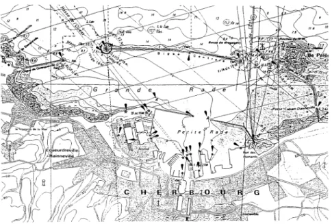
Before building a marina, it is indispensable to study its impact on morpho-logical evolution and on marine environment of the adjacent coastal zone. Thus, numerical simulations of tidal, wind-induced currents and wave agi-tation inside and outside the marina are needed. Generally, marinas have a complex geometry. The Cherbourg harbor is a typical example. It is composed of several roadsteads and small basins. The one is connected to the others (see Figure 1). Although the flexibility of single-block grid tech-nique, it can not be applied to many studies in which the computed domain is multiply connected. In order to increase geometric flexibility of comput-ing meshes, the other techniques are proposed. They are unstructured and bloc-structured grid ones (domain-decomposition grids, [4]) . Our interest is reported on this second option. The decomposition technique divides
514 Coastal Engineering and Marina Developments
the flow domain into sub-domains, which easily accept structured grids [5]. Thus, in order to obtain a fitting between the computing meshes and the marina area, the computed domain covering the marina and its adjacent coastal area should be divided into a few of blocks. Each block will be dis-cretized by a computed mesh. A multi-block technique is thus proposed to match the blocks.
The objectif of this paper is to describe in detail a multi-block implemen-tation of in the 2-D Shallow-Water model [3]. This model is based on a generalized non-orthogonal finite volume algorithm. Although in each block the computing mesh is structured, the block topology is essentially unstruc-tured. A block-connected matrix must be introduced to ensure an efficient inter-block communication. Currently, an implicit second-order UPWIND scheme is implemented in the model to handle the advection terms. The mathematical background of the model and the description of the multi-block technique are described in section II and III. Section IV presents several academic tests in order to validate the proposed technique.
Figure 1: Map of Cherbourg harbor
2 General Background
The governing Equations are the 2-D Shallow-Water ones in the water level-Discharge (j],Q\ formulation as follows :
dt + DIV (Q) = o (i)
Coastal Engineering and Marina Developments 515
yc + ^-^^ = 0(2) where 77 represents the water surface elevation, h the is bed level, while H = h + 77 is the water depth. U = (U, V) and Q = HU = (Q*,Qy) are, respectively, the depth-aver aged velocity and the unit-width discharge.
In this formulation, the depending variables are Q and 77, (u,v) design the velocity components, pr is the reference water density, fc — (—/Qy,fQx) is the Coriolis force. / represents the Coriolis parameter, ffc represents the bed shear^stress. Commonly, this constraint is linked to the depth averaged velocity U by a quadratic law.
(3) >h
CH is the Chezy coefficient. Afterword, we will note Ft> = -^-\/U^ + V* . The surface shear stress f%, is linked to the wind speed.
2.1 Curvilinear coordinate system
We note that {%$} is the Cartesian base and {£*'} the curvilinear base, a priori non orthogonal. We introduce a contravariant base \ b * > and the transformation jacobian J as follow [3]:
In the Finite Volume Technique, J represents the cell-control volume. In these notation, Eqs (1) are writen as :
7 t f °
-'"
where, U* - & • U and QJ - & • Q are respectively the /* velocity and unit-width discharge contravariant components, dji - ^j-An is the diffusion metric tensor, Qi and Si are the f^ unit-width discharge and source-term (Coriolis, wind affects, ...) Cartesian components.
2.2 Algorithm
These equations are solved in three implicit steps (with a splitting algo-rithm) using a Finite Volume Technique as showed in [3]. First, the ad-vection and dispersion affects are taken into account to calculate an in-termediate discharge Q*. Second, a Poisson equation gives the surface
516 Coastal Engineering and Marina Developments
elevation 77. And third, a correction equation taking into account the 77-gradient and other source terms (such as Coriolis and wind affects) gives the final discharge Q. A semi-implicit 0-scheme [7] is used in addition with an alternating direction method. Thus, the weight coefficients OD for the advection-diffusion step, and dp for the propagation step are introduced. Several techniques exist to handle the advective terms. Among them, the HYBRID scheme can be used [3]. The principle of this scheme is a bal-ance between a second-order centered scheme and a first-order UPWIND scheme depending on the Reynolds number. The HYBRID scheme gives good results for low Reynolds flows, but the accuracy diminishes when the Reynolds number increases. In coastal and estuarine regions, the flow is fre-quently dominated by the ad vect ion affects. Therefore, the Hybrid scheme becomes frequently a simple first-order UPWIND scheme, which risks to produce the numerical diffusion. In this context, a second-order UPWIND scheme is proposed to calculate strongly advective flows.
3 Multibloc Technique
The computed domain is covered by a global computing grid. It is composed of the sub-domain grids, which overlap. In the proposed multi-bloc method, each block is calculated separately and the matching of blocks is then made by a polynomial interpolation. In overlapping zones, the interpolation is explicit and respects the rule defined in [9] : an interpolated node of block k must be encircled by the nodes of block /where the nodal values are obtained directly from the resolving of 1-2. An iterative algorithm is introduced in order to obtain a good matching.
The multi-bloc algorithm is proposed as follows :
a Calculation of rf*+*,Q"+* for each sub-domain k at time tn+i with Eqs. (1-2),
b Correction of 77™+*, Q™+^ in the overlapping zones by the geometrical interpolation,
c Repetition of steps a-b until the convergence is obtained.
D
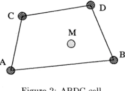
Figure 2: ABDC cell
Coastal Engineering and Marina Developments 517 Only the addresses of the matching points of block k and as well as the number of blocks / connecting block k are given in the input data. In the beginning of the program, we use an algorithm to find the address of the points, which encircle a matching point of block k and belong to block /, as follows:
Let's M be a given matching point belonging to block &, and A, B, C and D be the summits of a cell belonging to block /. In order to check if M is really inside the ABDC cell (Figure ....), the following boolean condition must be verified:
A BAM • nL A BfH > 0. and
A D^ > 0. and
>0.1 (6)
If the condition (6) is true, then A, B, C and D are the points encircling M. 4 Results
In this section, the proposed method will be validated by some benchmark tests. Two benchmark problems are presented here. The first test considers a jet-forced flow in a circular reservoir and the second one consider an unsteady separating flow in an expanding flume.
4.1 Flow in circular reservoir
Let's study a problem of the steady jet-forced flow in a flat-bed circular reservoir at low Reynolds number. The reservoir has a radius of R = 0.75m, the inlet and outlet channels both diametrically opposed of 0.157m wide and 0.3m long. The water depth is uniformly, h - O.lm. We defined the Reynolds number depending on the average velocity [// = O.lm/s, on the channel width b, and on the eddy viscosity AH in the inlet. A parabolic profile of velocity is imposed here, while the elevation is null in the out-let. On the walls, we imposed no-slip boundary conditions. The Reynolds number is R<, = 10 (the diffusion is AH = 0.00078).
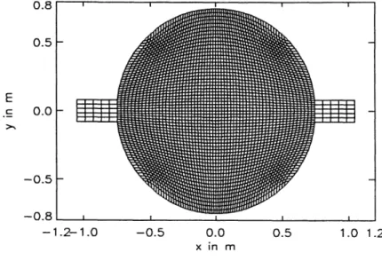
The area is decomposed into three distinct sub-domains : the inlet and outlet channels and the circular reservoir. As shown in Figure (Fig. 3), two coarse meshes (7 x 6) have been employed to discretised the inlet and outlet channels while a fine mesh covers the reservoir. The coarse mesh overlaps the fine one by a stitch to insure the complete recovering of the blocks. The time steps used is O.ls. The steady state was reached after t = 80s.
518 Coastal Engineering and Marina Developments 0.8 0.5 E c 0.0 -0.5 -0.8 -1.2-1.0 -0.5 0.0 0.5 1.0 1.2 3.0 2.5 2.0 1.5 1.0 0.5 0.0 -1:21.0 -0.5 0.0 0.5 x in m
Figure 3: Meshes for circular reservoir
1.0 0.5 > 0.0 1.01.2 -0.5 tT . . Borthwick 61*61 Multi-bloc technique * -1.0 -0.2 0.0 0.2 0.4 0.6 0.8 U/UI
Figure 4: Elevation along the basin axis and U-velocity along the medium plan
The results of the simulations are compared with the Borthwick and Karr's numerical solution (B&K, [2]). We also have two counter-rotating eddies on both sides of the throughflow jet. The center of these recirculations, at stagnation regions, are situated on the medium plane. The axial velocity on this plane is used to compare our results and Borthwick and Karr's (Figure 4b). The figure shows the free-surface elevation along the X-axis through the three meshes. One can observe that the free-surface is continued and smooth enough in the overlapping zone. We obtain the same accuracy as B&K's one.
Coastal Engineering and Marina Developments 519
4.2 flow in a flume to abrupt widening
Another application deals with a suddenly widening flume with the presence of a salient angle. This test is based on experiments conducted in 1981 and 1982 by Koppel&Wang and reported by Stelling&Wang [6] in 1984. Velocity fields and free-surface elevations were measured at the different instants. The proposed model was used to simulate the flow in the flume. The computed results are compared to the observations.
As shown by Figure 5a, the studied area is a 5 meter channel of 0.4m in the inlet and 0.8m in the enlarged zone. The bottom is flat (h=0.1m). The measurements were conducted with the discharge given by Q(t) — Qm sinwf where Qm = Q.QQ16m*/s and w = 27T/150 for 0 ^ t X 75s .
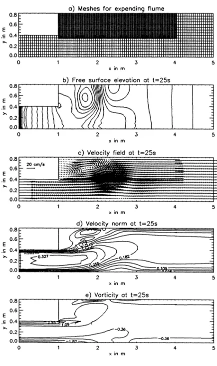
Using the multi-block technique, the flume is covered by three blocks (Fig. 5a). The first covers a rectangular area [O.,4.05] x [O.,0.4] using a 8 2 x 9 mesh. The second one, which is situated in the recirculation zone, covers a rectangular area defined by [l.,4.06] x [0.3428,0.8] using a 151 x 25 mesh. The last one, which is situated at the end of the flume, covers a rectangular area defined by [4., 5.] x [0., 0.8] using a 21 x 17 mesh. The bottom friction is characterized by the Chezy coefficient of 62.64 m*-^s~*. The eddy viscosity AH is taken as 2.3 lQ~*rn?s-*.
On the wall a no-slip boundary condition is used. On the inlet boundary (x=0), the unit-width discharge is imposed by Q* = Q(t)/QA and Qy = 0 , while the free surface elevation is calculated with the help of a radiation condition [1]. On the outlet boundary, a free-surface elevation condition is imposed as follows [6] :
rj(t) = 0 for 0 X t X 5 s rj(t) - ^^rfjsiujwt for 5 ^ t -< 75 s where 771 = 0.021 m, 7% = 0.001 m, 773 = 0.0005 m.
The time step is 0.1 s, that corresponds to Courant's number of about 7 for the wave propagation. The flow is characterized by the existence of a re-circulation zone due to the suddenly widening just after the inlet channel (Figure 5c). Table 1 gives the comparison between the length of the re-circulation zone LS , obtained by the experiment [6] and the proposed model. A coincidence is obviously obtained.
LS in m \ t in s measurment computation 15 0.7 0.68 25 1.4 1.35 35 1.9 1.8 45 2.3 2.25 55 2.4 2.5 65 2.6 2.73 Table 1: Length of rec-irculation region
520 Coastal Engineering and Marina Developments
0.0
0.8
0.8
O.o
a) Meshes for expending flume
b) Free surface elevation at t=25s
0.0
c) Velocity field at t=25s
d) Velocity norm at t=25s
e) Vorticity at t=25s
Figure 5: Meshes and results at t=25 sec for the flow in a flume with a sudden widening
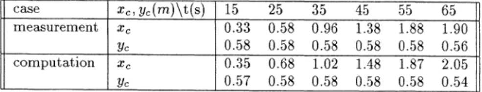
Coastal Engineering and Marina Developments 521 Table 2 presents the computed and measured co-ordinates of the center (%c, %/c) of the main eddy at different times. The computed values are close to the measured ones.
Figure 5b.d.e present the contours of water level, velocity norm and vor-ticity at time 25 sec. The development of the eddy is evidently displayed. Moreover, although the overlapping of neighboring blocks, it is clear that the contours of the water level and the velocity norm are completely smooth in the overlapping zone. Also, the flow pattern does present any irregularity there. case measurement computation %c,Z/c(m)\t(s) Xc Vc Xc Vc 15 0.33 0.58 0.35 0.57 25 0.58 0.58 0.68 0.58 35 0.96 0.58 1.02 0.58 45 1.38 0.58 1.48 0.58 55 1.88 0.58 1.87 0.58 65 1.90 0.56 2.05 0.54 Table 2: Coordinates (£c,2/c) of the center of the principal eddy
5 Conclusions
In this paper, a multi-block technique for calculating the water circu-lation in marinas of complex geometries is described. Block-overlapping arrangement is used. Several test-cases prove the interests of this method. An advantage of this method is the keeping of a structured arrangement of each block even for the applications to quit complex marinas. This reduces the computing time and then costs. An other interest is that we can use different resolution blocks in parallelly calculating coastal zones and harbor and marina areas, as proven in the second test.
References
[1] Blumberg, A.F. and Kantha, L.H., Open boundary condition for cir-culation models, J. Hydraulic Engineering, ASCE, 111, pp. 237-255, 1985.
[2] Borthwick, A.G.L and Karr, E.T., Shallow flow modelling using curvi-linear depth-aver aged stream function and vorticity transport equations. W. J. /or ATum. MetA. zn F/wck, 17, pp. 417-445, 1993.
[3] Guillou, S. and Nguyen, K.D., An Improved Technique for Solving the Two-Dimensional Shallow-Water Problems. International Journal for Numerical Methods in Fluids, 29, pp. 465-483, 1999.
[4] Lien, F.S. , Chen, W.L. and Leschzinder, M.A., A Multiblock Imple-mentation of a Non-orthogonal, Collocated Finite Volume Algorithm for
522 Coastal Engineering and Marina Developments
Complex Turbulent Flows. International Journal for Numerical Methods m FMds, 23, pp. 567-588, 1996.
[5] Baysal, O., Fouladi, K. and Lessard, V.R., Multigrid and Upwind Vis-cous Flow Solver on Three- Dimensional Overlapped and Embedded Grids. AIAA Journal, 29, pp. 903-910, 1991.
[6] Stelling, G.S. and Wang, L.X., Experimental computation on the un-steady separating flow on expending flume, Technical Report, No 84-2, Delft University of Technology, Depth, of Civil Engineering, Laboratory of Fluid Mechanics, 1984.
[7] Beam, R.M. and Warming, R.F., Alternating direction implicit methods for parabolic equations with a mixed derivative. SI AM. J. Sci. Statist.
1, pp. 131-159, 1980.
[8] Zang, Y., Street, R.L. , and KosefF, J.R.. A non-staggered grid, fractional step method for time-dependent incompressible navier-stokes equations in curvilinear coordinates. J. of Computational Phys., 114, pp. 18-33, 1994.
[9] Chessire, G. and Henshaw, W., Composite overlapping meshes for the solution of partial differential equations, Journal of Computational Physics, 90, pp. 1-64, 1990.