Publisher’s version / Version de l'éditeur:
Vous avez des questions? Nous pouvons vous aider. Pour communiquer directement avec un auteur, consultez la première page de la revue dans laquelle son article a été publié afin de trouver ses coordonnées. Si vous n’arrivez pas à les repérer, communiquez avec nous à [email protected].
Questions? Contact the NRC Publications Archive team at
[email protected]. If you wish to email the authors directly, please see the first page of the publication for their contact information.
https://publications-cnrc.canada.ca/fra/droits
L’accès à ce site Web et l’utilisation de son contenu sont assujettis aux conditions présentées dans le site LISEZ CES CONDITIONS ATTENTIVEMENT AVANT D’UTILISER CE SITE WEB.
8th IAHR Ice Symposium [Proceedings of the], 2, pp. 443-482, 1986
READ THESE TERMS AND CONDITIONS CAREFULLY BEFORE USING THIS WEBSITE. https://nrc-publications.canada.ca/eng/copyright
NRC Publications Archive Record / Notice des Archives des publications du CNRC :
https://nrc-publications.canada.ca/eng/view/object/?id=9caf88ce-a123-4ab0-a4c8-039683f4bd3f
https://publications-cnrc.canada.ca/fra/voir/objet/?id=9caf88ce-a123-4ab0-a4c8-039683f4bd3f
NRC Publications Archive
Archives des publications du CNRC
This publication could be one of several versions: author’s original, accepted manuscript or the publisher’s version. / La version de cette publication peut être l’une des suivantes : la version prépublication de l’auteur, la version acceptée du manuscrit ou la version de l’éditeur.
Access and use of this website and the material on it are subject to the Terms and Conditions set forth at
Field techniques for ice force measurements
Ser
1
TH1
National Research
Conseil national
N21d
Council Canada
de recherche$ Canada
1427
Institute for
lnstitut de
6. 2 I
Research in
recherche en
B W
Construction
construction
Field Techniques for Ice Force
Measurements
by K.R. Croasdale and R. Frederking
Appeared in
Proceedings of IAHR Ice Symposium 1986
lowa City, lowa, 18 - 22 August 1986
Vol. II, p. 443-482
(IRC Paper No. 1427)
Reprinted with permission
Price $4.00
NRCC 26719
BIBLIOTHEQUE
I R C
11 e x i s t e deux techniques de base pour mesurer l a pouss6e des g l a c e s sur un ouvrage : l 1 6 v a l u a t i o n sur place des contraintes sVexerl;ant dans l a couverture de g l a c e ou l a mesure de l a poussde exercbe sur l'ouvrage lui-m$me. Examen des appareils e t techniques u t i l i s b s . On indique l e s mdthodes
3
employer s e l o n l e s cas.IAHR Ice Symposium 1986
Iowa
City,
Iowa
FIELD TECHNIOUES FOR ICE FOKCE MEASUREMENTS
K. R. Croasdale Esso Resources Calgary
Frontier Section Head Canada Ltd. Alberta, Canada
R. Frederking National Kesearch Ottawa
Senior Research Officer Council of Canada Ontario, Canada
1.0 Introduction
Efforts expended on analytical solutions for ice forces and on laboratory testing of ice are of limited value unless full-scale observations and calibrations of ice structure interaction are also available. Without real-world experience and measurements it is doubtful if any substantial progress could have been made in understanding the physics of ice- structure interaction, and in developing workable engineering methods.
In recognition of the importance of obtaining actual measurements of ice forces, engineers have for a long time been developing measurement techniques. Many bridge piers, lighthouses and docks have been instrumented. More recently, the artificial islands and caisson
structures being used for exploratory drilling in the Arctic Ocean have been the subject of ice-interaction measurements. In addition, natural features such as small rock islands have been used as substitutes for real structures in order to study ice-structure interaction in
environments where no man-made structures yet exist.
In addition to providing a key to better predictions, it is important to recognize that the field measurement of ice forces is also an important
element of operational safety procedures. As engineers and operators
recognized the uncertainty inherent in ice force predictions, especially in new environments (which were not always well-known), it became
apparent that a real-time indicator of the force levels on a structure (andlor its response) could be a vital element in operational safety.
Therefore, from the time of the early artrificial drilling islands it has been quite common to link ice force instrumentation to operational alert procedures. Alert procedures have been described elsewhere, (Wright and Weaver, 1983) but briefly, as ice forces and/or structure deformations reach certain predetermined levels, operational procedures on the island are modified on a real-time basis. A typical extreme operational
response would be to secure the well and evacuate all but a skeleton crew. Such situations have been rare, but they have occurred. Obviously they are costly modifications to an already costly operation. When ice force measurement devices are linked to such operational procedures then of course it is of paramount importance that the ice force measurements
(and their interpretation) are reliable and reasonably accurate.
Observation and measurements of ice-structure interaction have been conducted worldwide, but because of the background and experienc of the authors, this review paper will focus primarily on techniques developed and applied in North America, especially in Canada. It should be emphasized however that the international scientific and engineering community has contributed significantly to this topic; although it was in Canada where most of the new techniques for arctic structures were
applied first.
2.0 Overview of Methods of Approach
When ice pushes against a structure a force is generated. According to Newton's Law, the force is equally and oppositely applie to both the structure and the ice. Therefore to measure the interaction force we have a choice of measuring either the response o the structure, or the response of the ice. This distinction broadly categorizes the two fundamental approaches, namely;
- in situ measurements on the ice,
- structural response measurements.
Each approach has its advantages and disadvantages, ideally both methods should be used together, but in some situations only one of the
approaches will be feasible.
For example, in dynamic ice situations where the ice is continuously moving, it is preferable to instrument the structure, because in situ instruments on the ice will quickly move by the structure. On the other
hand, once the ice around a structure has become landfast (and subject to relatively small movements) it will often be preferable to instrument the ice surrounding the structure, (especially if the structure is an
artificial island surrounded by a grounded rubble field and therefore difficult to instrument for global ice loads).
For discrete ice features, such as isolated multi-year floes or icebergs, measurements of the deceleration and motions of the ice as it interacts with the structure can be used to deduce the global ice forces.
On a structure we have the choice of either measuring the actual ice pressures at the ice line, or measuring the global response of the structure. Neither approach is simple, and both methods have their difficulties when the structure is large and has redundant load paths. Ice pressure panels at the ice line have the advantage that local
variations in ice pressure can also be measured. But unless a continuous band of load panels is placed around the structure (an expensive
proposition on a large structure), considerable interpolation and extrapolation is required in order to predict global forces from a limited number of local ice pressure readings. Also, sloping structures are not amenable to this form of instrumentation for global forces.
Internal strain gauging of structural elements is often a popular method, but interpretation usually requires either a full-scale calibration or a reliable structural analysis.
Another approach is to use soils instrumentation (e.g. total pressure cells, slope indicators, piezometers etc.) either in the foundation or interior fill. The major drawback of this approach is that under service loads, the response of the soil is often too small to be measured
reliably.
3.0 In Situ Methods 3.1 General
Superficially it would seem to be a relatively simple matter to measure in situ stresses in an ice sheet. Why not simply measure strain and convert to stress using a value of modulus for ice? Alternatively why not install in the ice a hydraulically filled flat jack connected to
a pressure transducer and measure the pressure as the ice is stressed? Both of these approaches are simple, and have been used with other
materials including soils and rock; what are the issues relating to their use in ice?
First, in ice, the simple conversion of strain to stress is fraught with difficulty, because ice is not a linear elastic material. Ice is a
material close to its melting point and therefore exhibits creep. When ice is loaded with a constant stress it initially deforms elastically (i.e. if the load is removed the strain returns to zero) but after a few minutes (or less) the ice creeps. Initially there is a primary creep phase in which the strain rate is decreasing with time. This phase is followed by a secondary creep phase in which the strain rate is constant, and finally there is a tertiary creep phase in which the strain rate increases to failure. These different creep regimes make the
interpretation of a simple strain measurement extremely difficult, especially since the elastic and creep deformation characteristics vary with ice temperature, crystallography, salinity and stress level. In fact, it is generally recognized by proponents of strain meters that ice stress can be interpreted sensibly only when the ice is in secondary creep. In that phase, there is a unique relationship between strain rate and stress according to Glen's law
where is strain rate; a is stress, n is equal to about 3, and A is a coefficient depending on ice characteristics such as temperature, salinity and crystal structure. Thus, strain meters, according to the theory of ice deformation, may be useful only to measure loads applied long enough for secondary creep to be established (about 45 minutes or more).
The use of strain meters will be discussed later. At this point, it is interesting to note that historically, because of perceived difficulties in relating ice strain to stress, ice engineers have pursued the concept of an in situ stress sensor which would be insensitive to varying ice deformation characteristics resulting from creep and to the effects of
varying ice properties such as temperature, salinity and crystal structure.
3.2 Theory of ice stress sensors
There are problems associated with insertion of a sensor into an ice sheet and interpretation of the results. First, an inclusion in an ice sheet can lead to a disturbance of the stress field such that the stress experienced by the sensor is different from the stress in the sheet had the sensor not been there. This problem has been addressed by several investigators (Metge et al, 1975; Templeton, 1981; Chen, 1981) and elastic theories have been developed which relate sensor stiffness and geometry to the modulus of the surrounding material.
Typical results from this theory of inclusions are reproduced in Fig. 1. The results show obviously that the ideal sensor should have the same modulus or stiffness as the ice. So why not build sensors according to such a specification? The problem, discussed earlier, is that the relationship between stress and strain (modulus) for ice is complex and there is no unique value. Ice modulus varies with temperature, salinity, crystal structure and, because of creep, with time of loading. Therefore the ideal sensor should read the ice stress regardless of the modulus of the surrounding ice. How can this be achieved?
The first attempt to rationalize sensor design was described by Metge et a1 (1975). A wide thin sensor was proposed with sufficient stiffness that as the effective ice modulus varied, the ratio between ice stress on the sensor and stress in the ice remained constant. As can be seen from Fig. 1, this should result in an inclusion factor (stress ratio)
remaining close to 1.0. This then would be the ideal sensor form, and it is the reason why several sensors of this type have apperared.
The equation for Figure 1 is of the form: (Chen, 1981)
Where a is the undisturbed stress in the ice
al is the average stress felt by the sensor El
E I s the elastic modulus of the
sensor
D is the width or diameter of the sensor in a direction perpendicular to the stress
H is the thickness of the sensor in the stress direction
N is a property of the ice such that it is analogous to the subgrade reaction.
Chen recommends that the value of N/E be taken as 1.0 based on both theoretical and experimental examination of the problem. Thus equation (2) reduces to
This equation is very similar to the one proposed by Metge et a1 (1975) and yields a graphical result very similar to Figure 1.
Templeton (1981) provided a very thorough analysis of the embedded ice
sensor problem and confirmed the use of an equation similar to (3). He
also examined the effects of differential thermal expansion and the effects of transverse pressure (biaxial stress), and developed equations
for their effects. Ile concluded that their effects on sensor accuracy
could be minimized by maximizing the width-to-thickness ratio, i.e. using a thin wide sensor.
Despite this sound theoretical and practical basis for thin wide sensors, others have developed symmetrical cylindrical sensors. These have the advantage of biaxial capability and can usually be inserted into an augered hole.
The theory of biaxial cylindrical sensors has been developed and reported
on by Cox and Johnson (1983). Their analysis yields, for a very stiff
sensor, a value of al/a = 1.5 which is the same result as given by
equation (3). Therefore, a stiff cylindrical sensor should have an
inclusion factor of about 0.67 to obtain values of undisturbed ice stress. However, interpretation is not simple, because of the biaxial nature of the gauge. Readers are referred to the report of Cox and Johnson (1983) for the full theoretical treatment.
Even if we can accurately measure ice stress at discrete points in an ice sheet pushing against a structure, a remaining problem is that of
converting these readings into a global load on the structure. A typical deployment of stress sensors in the ice around a structure is shown in Figure 2 (Netserk F-40, instrumented by Esso Resources Canada Ltd. in 1976). The theoretical approach to the problem is to calculate stress fields in the surrounding ice, match the readings from the stress sensors to the theoretical stress fields, hence to deduce the global load on the structure.
Initial application of this approach assumed elastic properties for the surrounding ice; more sophisticated approaches assume elasto-plastic ice properties and/or take into account modifications to the stress
distribution due to ice creep. Wang and Ralston (1983) examined the radial stress distribution in an ice sheet pressing against a circular cylinder (with a frictionless boundary condition). A typical result of their analysis (Fig. 3) shows that a simple elastic analysis gives a good approximation for radial stress decay. Furthermore it shows that if a stress sensor is placed at a distance of one structure radius away from the structure typically it will measure about 60% of the ice pressure acting at the ice structure interface.
Naturally given adequate resources, the placing of several sensors along radial lines out from the structure would be desirable in order to confirm and/or calibrate such theoretical predictions.
It should be noted also that variation in ice modulus and thickness and the presence of cracks can seriously affect the prediction of global loads on the structure from in situ sensor readings.
3.3 Types and history of ice stress sensors
The first in situ ice pressure sensor (known to the authors) was developed at the University of Alaska in the early seventies (Nelson, 1975). The University of Alaska sensor was a small stiff sensor based on a strain-gauged metal cylinder. About the same time, the National Research Council in Ottawa developed a small soft sensor based on a thin-walled metal cylinder (Frederking, 1980).
Esso Resources Canada contracted the University of Alaska to install some of its sensors around some of the early artificial islands in the
Beaufort Sea. Mfficulties in interpretation of a small stiff sensor led Esso to develop the wide thin soft sensor which was subsequently used quite extensively by Esso around its islands (Metge et al, 1975).
The Esso sensor was later improved upon by Exxon who maintained the geometry of the Esso sensor but redesigned it internally to achieve better linearity and a different stiffness (Templeton, 1979; Chen,
1981).
During the late 1970's and early 19801s, a large variety of sensors started to appear. The original Esso design was again used as the basis for the MEDOF panel used by Dome around the Tarsiut island (Pilkington et al, 1983). Oceanographic Services developed a small cylindrical hard sensor which could be installed in a hole cored in the ice sheet (Johnson and Cox, 1980). ARCO Oil and Gas Company developed a sensor based on the flat jack principle (McBride, 1981). More recently, Arctec Canada has built a thin wide metal sensor called the Hexpack (Graham, et al, 1983). Other Canadian companies have developed both biaxial and panel type sensors as well as hydraulic disk types.
In terms of generic types, most of the above sensors can be considered to fall into two broad categories;
-thin wide sensors with a stiffness close to that of ice, and -small stiff sensors
In a category of its own is the ARCO hydraulically filled disc, which is thin in relation to its diameter, but is small (about 4 inches in
diameter) in relation to the ice thickness.
The thin wide panel sensors are generally arranged to measure the ice stress through the full ice sheet thickness. Their sensing elements can be wired-up to give either the average compressive stress through the thickness or the ice stress at various levels through the ice thickness.
Obviously small sensors can only measure stress over a small area,
therefore, several may be needed through the ice sheet thickness in order to obtain an integrated stress for load. Thin wide sensors can usually
measure stress only in one direction, small cylindrical sensors can measure the principal stresses and direction. Of course any uniaxial sensing unit can be arranged in a rosette to enable principal stresses at a point to be measured.
3.4 Ice strain meters
Surface strain meters for use on sea ice have been in use for over a decade. Goodman (1980) describes their history and technical details. The original design was based on an invar wire and could typically resolve strain to Moore and Wadhams (1980) describe a rod strain meter which is generally more robust and portable than the wire gauge but with less resolution (10'~).
Strain meters have been used to study the response of ice floes and icebergs to wave action (Goodman et al, 1980) and to conduct strain measurements in floating ice platforms (Anderson and Perry, 1980). Prodanovic (1978) describe a steel rod strain meter which was used to study strains in the land fast ice in the Alaska Beaufort Sea. More recently strain meters have been used on ice around structures in order to estimate ice forces. British Petroleum have pioneered this latter application (Goodman 1983; Sandereon et al, 1983; Frederking et al,
1984).
Strain meters have certain advantages over stress meters,
-
they are easily deployed-
they do not disturb the ice stressOn the other hand, they have certain disadvantages,
-
they measure only surface strain, bending strains may mask the compressive strains of interest-
their interpretation requires an intimate understanding of how strain rate relates to ice stress for different kinds of ice at various temperatures and salinities.It is beyond the scope of this paper to present the theory for the interpretation of strain meters. The reader is referred to Sanderson (1984) for more details.
For additional discussion of various sensor types and their history refer to 4th Report of Working Group on Testing Methods in Ice, IAHR (1984).
3.5 In situ sensors
-
performance dataDuring the development and application of in situ ice sensors, a variety of tests have been performed to establish sensor characteristics and their response in controlled load environments. Basic performance data required for all sensors is a calibration of output against applied stress. For most sensors this is easily done in a loading press. Such tests also will indicate any fundamental problems such as non-linearily and hysteresis which could adversely affect their interpretation. Tests conducted in a sensitive test machine can also give the stiffness of the sensor which may be required to interpret the results using inclusion theory.
Calibration and testing of an ice sensor in a press is relatively simple, but does not confirm whether the sensor behaves as expected when it is contained in an ice sheet. Therefore, tests of sensors in ice under controlled load conditions are very important in establishing confidence in their readings. Until recently few tests of this nature have been performed. The exceptions were tests conducted on the Esso panel
(Trofimenkoff, 1977), tests conducted on the Exxon panel (Chen 19811, tests conducted by Frederking (1980) on a cylindrical sensor and tests conducted on a biaxial cylindrical sensor (Johnson and Cox, 1980; Cox, 1984). The latter tests were conducted in the laboratory using both saline and fresh water ice under both uniaxial and biaxial stress conditions. Laboratory testing of this sensor was feasible because of its small size (5.72 cm diameter). Typical results from these tests showed good agreement between applied and measured stresses (within 15%), a resolution of about 20 kPa, and a temperature sensitivity of about 5 kPaIoC.
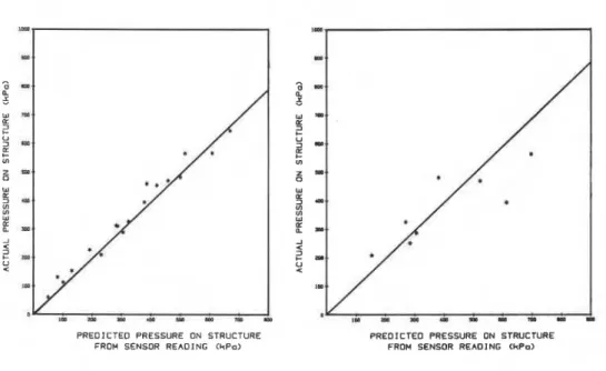
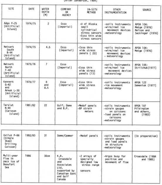
In a recent experiment, ten sensor types were tested in a large outdoor ice basin under controlled load conditons (K.R. Croasdale and Associates Ltd, 1984; Croasdale et al, 1986). The ice sheet was approximately 0.7 m thick, 50 m long and 30 m wide. Loads up to 1400 kN were applied at one end and reacted against an instrumented structure 3 m wide at the other end. The sensors were placed in the ice in front of the structure analogous to how they might be used in the field in an ice sheet
was to evaluate how well sensors of various types could predict the forces on a structure, for both short- and long-term loads.
Twenty two separate tests were conducted at a variety of load levels. For most of the tests, most of the sensors yielded an output which
generally tracked quite well the applied load on the structure. For each load plateau tested, the ouput from each sensor was converted to an average pressure across the reaction structure assuming an elastic stress distribution in the ice sheet.
For each sensor it was then possible to present the results as actual pressure on the structure (obtained directly from the load cells supporting the reaction structure) against predicted pressure on the structure obtained from the sensor reading. Results obtained for a typical panel-type sensor are shown in Figure 4. The panel measured the average ice stress through its thickness. Where small sensors (e.g. hydraulic disks) were used these were arranged in a rosette at two levels in the ice sheet. The average of the outputs from the two levels was used to obtain the results shown in Figure 5. Results obtained from the stiff cylindrical bi-axial sensor are shown in Figure 6 . The slightly greater scatter obtained from this sensor is most likely due to the problem of using the measured stress as the average through the ice thickness. It was recognized that in some of the later tests, bending was induced in the ice sheet due to tilting back of the reaction
structure. This bending of the ice sheet, although not detectable to the eye, also severely affected the use of the strain meters to predict loads on the structure.
In general, the experiment showed that in situ ice stress sensors of various generic types did respond as expected. For example, the panel-type sensors had inclusion factors close to 1.0, which did not change significantly with the time of applied load, i.e. creep. The experiment also indicated that for those sensors which were operational, the average percentage difference between the actual load on the
structure and that obtained from the sensors readings was better than about 30%. Sensors which sampled at various levels in the ice sheet showed that a redistribution of stress through the ice sheet thickness did occur under long term loads, presumably due to creep. These results
emphasize the need to measure ice stress at more than one level through its thickness.
3.6 In situ sensors
-
case historiesThe exploratory drilling islands which were built in the shallow waters of the Beaufort Sea commencing in 1973 provided a major incentive for the development and application of in situ ice stress sensors. Artificial islands are not easily instrumented for ice forces, especially if they become (as most do) surrounded by a grounded ice rubble field. Under these circumstances, about the only feasible method of deducing ice forces is to install in situ sensors in the ice surrounding the island and grounded rubble.
Initial efforts were based on a small hard sensor developed at the University of Alaska (Nelson and Sackinger, 1976). In addition, Esso's research department in Calgary, which was responsible for the monitoring of the early island, developed a thin wide soft sensor designed to
penetrate the full ice thickness. These were usually arranged to measure radial stresses applied to the island (Figure 2). They were usually hard-wired back to a central data acquisition system on the island. Soils instruments, such as slope indicators and piezometers, were often also installed at a site, as well as devices to measure relative movement between the ice and the island.
Table 1 is an extension of a similar table originally prepared by
Sanderson (1984). It summarizes the applications of in situ ice sensors (to measure ice forces) which has occurred in the Canadian Arctic from 1974 to the present. As Table 1 indicates, the first five islands were all instrumented in a similar fashion using Esso panels. The data gathered provided confirmation of design criteria and insights into ice structure interaction processes. As well, the instruments were linked to a real-time ice alert and ice defence system, which provided comfort to both the operating staff, management, and regulators, especially as islands were being built in ever increasing water depths.
Results from these early ice force monitoring projects are contained in the original company reports which are now available through APOA (see Table 1). Sanderson (1984) refers to the results and provides a brief
discussion of an event during which ice stresses up to 1.0 MPa were measured. Interpreted average stress across the island width was 1.2 MPa.
In 1981 the Tarsiut caisson island was constructed in 22 m of water. It was a significant departure in design from the dredged islands built to that time. Therefore it was decided to invest heavily in instrumentation for both operational safety and research purposes. The two seasons of data gathering at Tarsiut are referred to in Table 1 and have been discussed by Sanderson (1984), and Pilkington et at (1983). Note that the Medof panel is based on the internal design of the original Esso panel but uses the volume change of a fluid to indicate strain (the original Esso sensor measured capacitance). Also note that the Tarsiut second-season program utilized surface strain meters as a method of estimating total loads on the island (Sanderson, 1984). No results from the Tarsiut monitoring programs have yet been published but Pilkington et a1 (1983) notes that "The strain-gauged flat jack panels (on the structure) and the Medof panels (in-situ) provided the best ice load information, and generally, reasonable agreement was noted between these instruments where they could be compared."
Adams Island is a small natural rock island at the north end of Baffin Island. It was chosen by the National Research Council of Canada as a site to conduct ice interaction research. In situ instruments, both stress meters and strain meters were used. Details of the programs and results are given by Frederking et a1 (1984 and 1986). A typical output from one of the biaxial stress sensors is shown as Figure 7. Maximum principal compressive stress measured in the ice was about 350 KPa. (The ice was land-fast, with movements up to 300 mm/day and a strong tidal cycle).
The Nanisivik Dock on Baffin Island was also a site where in situ instruments were deployed during the winter of 1983184 (see Table 1). Four different types of stress sensor and one strain meter were used. The overall objective of the program was to compare results from a variety of sensors installed at the same location. The results are described by Croasdale (1985). In general, compressive stresses in the ice around the dock were low. There was a strong tidal cycle causing
bending i n t h e i c e s h e e t which a l s o induced c r a c k i n g of t h e i c e . The bending and c r a c k i n g of t h e i c e made comparison between s e n s o r s r a t h e r d i f f i c u l t .
The i n s t r u m e n t a t i o n of t h e Esso c a i s s o n r e t a i n e d i s l a n d h a s been
d e s c r i b e d by Hawkins e t a 1 (1983). A t both s i t e s where t h e c a i s s o n h a s been deployed (Kadluk and Amerk
-
s e e Table l ) , i n s i t u i c e s e n s o r s have been deployed a l s o . R e s u l t s from t h e i n s i t u s e n s o r s a r e r e p o r t e d by Johnson e t a 1 (1985), Croasdale (1985), Sayed e t a 1 (1986). At t h e Amerk l o c a t i o n i c e p a n e l s were p l a c e d i n t h e r e f r o z e n i c e r u b b l e s u r r o u n d i n g t h e c a i s s o n . The o b j e c t i v e of t h e program w a s t o i n v e s t i g a t e l o a d t r a n s f e r through t h e grounded i c e r u b b l e t o t h e s t e e l c a i s s o n . The r e s u l t s of t h e work i n d i c a t e t h a t a t low l o a d l e v e l s ( i . e . 250 kPa a p p l i e d a t o u t s i d e edge of r u b b l e ) , a l l t h e l o a d a p p e a r s t o bet r a n s f e r r e d t o t h e underwater berm v i a t h e grounded i c e r u b b l e , and t h e c a i s s o n s s e e no load.
R e s u l t s from t h e m o n i t o r i n g of t h e SSDC a t Uviluk and o t h e r l o c a t i o n s have n o t been p u b l i s h e d y e t .
One o t h e r a p p l i c a t i o n of i n s i t u s e n s o r s which i s i n i t s e a r l y s t a g e s (and i s r e f e r r e d t o i n Table 1 ) i s t o measure t h e d r i v i n g f o r c e s i n t h e p a c k l c e . In t h e c o n t e x t of i c e f o r c e s , t h e i n c e n t i v e s f o r s u c h
measurements was d i s c u s s e d by Croasdale and o t h e r s i n 1984. A p r o j e c t on t h e t o p i c f i n a n c e d by t h e Government of Canada ( p r o p o s a l
-
Croasdale, 1985) l e d t o a t r i a l deployment of s e n s o r s i n a m u l t i - y e a r f l o e i n t h e s o u t h e r n Beaufort Sea i n A p r i l 1986. The s e n s o r s had been s p e c i a l l y d e s i g n e d f o r t h e low s t r e s s e x p e c t e d , and e x t e n s i v e l y c o l d room t e s t e d p r i o r t o f i e l d deployment. The r e s u l t s from t h e program w i l l be p u b l i s h e d i n 1987.3.7 I n s i t u s e n s o r s : comments on i n s t a l l a t i o n and removal
Panel-type s e n s o r s a r e u s u a l l y i n s t a l l e d u s i n g long-bladed c h a i n saws. The t h i c k e r t h e i c e t h e more d i f f i c u l t t h i s o p e r a t i o n becomes. I c e up t o about 1 m t h i c k i s u s u a l l y no problem, i c e t h i c k e r t h a n 1.5 m p r e s e n t s q u i t e a c h a l l e n g e . Even though p a n e l s e n s o r s a r e t h i n , t h e y a r e t h i c k e r t h a n a normal c h a i n saw b l a d e and i t i s u s u a l l y n e c e s s a r y t o make two p a r a l l e l c u t s about 10 cm a p a r t . Care s h o u l d be t a k e n t o a v o i d b r e a k i n g
through to water until the full slot perimeter has been cut as deep as possible (dry slots are easier to cut than wet slots, especially in extremely cold weather).
If a chain saw is not available a slot can be made using a continuous line of augered holes, broken between if necessary, using an ice chisel. Where a major installation of ice panels is planned around a structure, a tractor equipped with a ditching blade is well worth having, and will save considerable labour. Slots can also be cut with steam or hot water, which incidentally, is the preferred method of panel removal.
Panel-type sensors should never be placed closer together than about 2 m. It is important to perform final checks on the sensor operation and to take zero readings prior to installing the sensors in their slots (recognizing that the temperature of the sensor lying on the ice will
usually be calder than when it is frozen in). Freezeln stresses will
often be recorded by sensors (typically up to 350 kPa), but they are usually relieved by creep over a period of the first few days of operation of the sensor.
Smaller cylindrical and disk-type sensors (say less than 10 cm diameter) can be installed in augered holes. This operation of course is much easier. In this case the depth of the holes can be set less than the ice thickness and the sensors flooded from the top. The only advantage is to be able to use fresh water rather than saline water when operating on sea ice. Experience indicates that under typical winter arctic conditions the choice of sea water or fresh water as a backfill material is not critical. Under warm conditions, fresh water is preferred in order to avoid the low modulus associated with warm saline ice. Under relatively warm conditions the freezing-in process can be accelerated by using a pack of dry ice at the surface and by putting back the ice cuttings into the augered hole after sensor installation.
In situ calibrations of ice sensors have been attempted using thin flat jacks inserted into slots close to the sensors. Results from these calibrations are often ambiguous because of uncertainty about the actual stress distribution induced in the ice by the flat jack. For sensors which are temperature sensitive it is usually necessary to install a
thermistor string close to the sensor through the ice thickness. Sensors should be installed in a flat and even area of the ice sheet, away from any cracks which may already be in the ice. If it is not possible to install a rosette of stress sensors, then a strain meter rosette on the ice surface near the stress sensor may be very helpful in interpretation of the stress readings.
3.8 In situ ice sensors
-
the futureThe technology of ice stress sensors is now reasonably well developed. Sensors of various geometries ranging from thin wide panels to small stiff cylindrical sensors appear to function satisfactorily. Remaining problems are;
-
improving installation and removal procedures especially forremote applications;
-
development of a sensor which does not have to be frozen-in (forsunnner multi-year floe impact studies either by ships or against structures);
-
reducing sensor costs (so that they can be abandoned ifnecessary);
-
further work on low stress range sensors for pack ice forcemeasurements (work on this has already started; Croasdale, 1985).
4.0 Ice Forces from Floe Motions
Another approach to measuring ice forces during ice-structure interaction is to deduce the ice forces from floe motions during an impact. Such an approach was used at Hans Island in 1980, 1981 and 1983. At Hans Island the decelerations of multi-year floes impacting the island were measured. By also estimating the mass of the floes, the ice forces acting between floe and island were deduced. These experiments have been described by
Metge et a1 (1981) and Danielewicz et a1 (1983). Readers are referred to
these references for a detailed discussion of the technique.
5.0 Loads on Structures
5.1 General
Where structures are placed in ice-covered waters an opportunity is presented for direct measurement of ice loads. Generally this can be accomplished by one of three fundamental approaches: (i) measure
of load sensing panels to the structure, and (iii) in cases of dynamic loads, measure accelerations of the structure, which, when combined with a knowledge of the dynamic response of the structure, allows loads to be determined. All three, but particularly the first two approaches
generate information relevant to both local and global ice loads.
The first direct measurements of ice loads were on hydraulic structures such as bridge piers, dams and lighthouses. Measurements were carried out in the Soviet Union, United States of America, Germany, and Canada prior to 1970. In the past decade and a half, efforts have concentrated on measurements on offshore structures in marine environments. As indicated in the introduction, this review will concentrate on more recent experience in North America. Each of the three measurement approaches will now be considered in general. The remainder of this chapter will contain a number of case studies, critical comments and a concluding statement on the current status and future directions.
5.1.1 Structural measurements
The structure itself can be used as a transducer by measuring strain in components of the structure, relative deformations between parts of the structure, or absolute movements of the structure. In all cases some form of calibration is needed to convert the measurements into ice loads. Conversion can be accomplished by analytical calculations or by physical load calibration tests. Analytical calibrations require an accurate description of the geometry of the components of the structure, the nature of the interconnections between the components, and the
constitutive relations for the materials from which the components are constructed. In large steel or reinforced concrete structures such analytical expressions generally exist since they are used in design. However they require adaptation to make them suitable for load
predictions. When such expressions can be derived with adequate
accuracy, point loads or load distributions can be deduced from strain or deformation measurements in the structure. Ambiguities in interpretation may arise due to redundancies in the load paths between load application points and strain gauge locations. Analytical calculations also are required to optimise the location of instrumentation.
Alternatively, physical calibration tests can be done, i.e. known loads or load distributions are applied to the structure and the resulting strains or deflections are measured. Physical calibrations potentially are more accurate provided that the nature of the actual ice load is correctly anticipated. However, physical calibrations are expensive to perform and have a limit on how far they can be extrapolated. Ideally a combination of physical and analytical calibrations should be used.
The actual type of transducer used in this type of measurement includes strain gauges or displacement transducers. Strain gauges are bonded to parts of the structure which are expected to have high sensitivity and accurate response to the anticipated loads. Similarily, displacement transducers, pendulums, borehole inclinometers or laser beams have been used to measure relative displacements between different parts of a structure. Surveying instruments including laser ranging devices are used to measure absolute displacements of the structure.
5.1.2 Add-on transducers
Load sensing panels have been placed on or in the outer surface of structures to measure ice loads. These are special purpose instruments which are designed or adapted to directly measure ice loads. In essence they consist of some sort of plate or panel to collect ice load and a load measuring transducer. The collector panel can vary in size from a few millimeters to a few meters. The load measuring transducer can have several levels of sophistication; i,e. measure total normal loads, shear loads and load distributions. They can provide information on global loads, local loads and pressure-area distributions.
Load or pressure panels are a more direct way of measuring ice loads than structural measurements, but bridging effects (similar to the inclusion problem of in situ transducers) present problems. It is necessary to match the stiffness and surface characteristics of the transducers to those of the structure. This task is not trivial. If the sensor is stiffer than the surrounding structure it will tend to collect load and if it is more compliant it will tend to shed load. Ice is not purely elastic nor a simple fluid, but is visco-elastic, so the redistribution of pressure is complex. It is desirable that calibrations be carried out using ice.
No theory, similar to that for in situ transducers, has been developed for the design and placement of force or pressure transducers on structures subject to ice loads. Graham et a1 (1983) have sugested criteria, which, while developed for soils, could in the absence of any other guidelines, be applied for ice. The following criteria might be applied: (i) for a diaphram type pressure sensor under a uniform pressure the ratio of diaphram diameter to centre deflection should exceed 2000 at rated pressure, (ii) for a rigid plate transducer the ratio of diameter to deflection should exceed 10,000 at rated load. This is a subject which requires further work.
One class of transducer includes small circular diaphram types which use strain gauges or pressure gauges to measure ice pressures on their
sensing surface. The sensing surface is generally mounted flush with the structure surface. The other class of transducer uses a large panel with some type of load cell sandwiched between it and the structure. The load cells employ strain gauges or hydraulic pressure tranducers as sensing elements.
5.1.3 Accelerometers
In the case of dynamic loading it is possible to use accelerometers to measure the dynamic response either of components or the total structure. Knowing the dynamic characteristics of the structure, dynamic ice loads can be determined from acceleration measurements. The dynamic equations of equilibrium are:
[m]
{a}
+ [c]{ b }
+[K]
(6) = {~(t,8)}where [m], [c] and
[K]
are the mass, damping and stiffness matrices, respectively, of the structure,{F}
is the ice forcing vector which is a function of time and perhaps velocity, and6
is the displacement vector. The dot refers to the time derivation. With a knowledge of theacceleration, 6, velocity, 8, displacement, 6, and the structure characteristics the ice force [F} can be calculated. Again there is a necessity for a calibration. This can be accomplished by analysing the structure to determine its modes and frequencies of vibration. If
damping is an important factor the analysis is difficult because there is no accepted means for calculating the effect of damping. Alternatively
physical calibrations can be carried out whereby a known load is applied to the structure and the dynamic response measured. From the dynamic response a transfer function can be derived which allows dynamic forces to be calculated from measured accelerations.
5.2 Ice load case studies
As mentioned in the introduction of this chapter there have been a number of projects to measure ice loads on structures. A partial inventory of such projects, together with some of their salient features is presented in Table 2. In selected instances more detailed information follows.
5.2.1 Bridge piers
Work on bridge piers has shown that simple load measuring systems, noses or piles hinged below the water line and supported by a load cell above
the water line, are most reliable. They only produce information on total loads, however, such systems can be made relatively stiff and rugged to obtain ice loads independent of the measuring system
characteristics. The piers themself may have a natural frequency in the range of the applied ice loads. Therefore it is important to know the dynamic characteristics of the pier so that true ice forces can be interpreted, free of any resonant condition. Whatever type of ice load measurement is made, it is highly desirable that realistic physical calibration tests be carried out. This is particularly so in the case of dynamic loading.
5.2.2 Lightpiers
Techniques for measurement of ice forces on lightpiers are similar in many respects to those of bridge piers. An additional approach which was developed for lightpiers is to measure the acceleration response of the pier to ice loads. Combining the accelerations with the structure characteristics, as discussed in section 5.1.3., ice forces can be calculated. One major problem with measurements on lightpiers is accessability. It has been necessary to have reliable self-contained instrumentation systems on the pier combined with either a telemetry system for transferring data to a shore station or a recording system on the pier with sufficient capacity to last throughout the measuring season, which could be up to 3 or 4 months.
5.2.3 Petroleum exploration structures Tarsiut
Tarsiut is the location of a concrete caisson retained island in the Beaufort Sea. It comprises 4 sand-filled caissons which in turn enclose a sand-filled core. The structure is about 100 m across at the water line and has a vertical outer surface. The caissons are 10 m high and rest on a berm which comes to within 6 m of the water surface. The structure was extensivley instrumented to measure ice loads (Pilkington et al, 1983) both for operational safety reasons and for future design. See Figure 8 for a schematic presentation of instrumentation locations.
Instrumentation comprised sensors to measure loads on the outer face, strain gauges embedded in the concrete and geotechnical sensors in the foundation and core. The strain gauges were of a weldable type and were attached to the steel reinforcing rods in the concrete. Gauge locations were selected on the basis of finite element calculations which also provided calibration coefficients for converting the measured strains to ice loads. From the distribution of gauges it was possible to establish load distributions and global loads. In spite of the care taken in the installation of gauges and cables, only a third of the gauges were operational at the begining of the measurement program. Fortunately there was sufficient redundancy that useful results could still be obtained. A system of four 4 m by 4 m flat jack panels was attached to the outside of the east caisson (see Fig. 8 for locations). The outer face of each panel was a 89 mm thick steel plate to ensure that applied ice loads were uniformly distributed to the 16 flat jacks behind each panel. Pressure transducers measured the flat jack pressures.
Circular load cells were mounted in 880 mm diameter recesses in the north caisson. The sensing face was supported on shear bars or spiral coil hydraulic hoses. For more details on the characteristics of these transducers see Graham et a1 (1983). The shear bar transducers had a number of desirable features (low temperature coefficient, no creep and high stiffness). The spiral coil transducers had less desirable features but were inexpensive. Unfortunately a storm in the autumn led to water entering these gauges and making a number of them inoperable. Finally eight 50 mm diameter microstud gauges were installed in one of the flat
jack panels to measure local pressures. These were a diaphram type of pressure gauge.
Experience over the winter 1981182 showed that the embedded strain gauges and flat jacks provided consistent and reasonable ice load information. Inclinometers provided qualitative confirmation of major ice loading events and quantitative information for operational purposes.
Single Steel Drilling Caisson
The SSDC is a converted super tanker which has undergone extensive modifications to adapt it for use as a support structure for year-round exploratory drilling in the Beaufort Sea. The structure is 162 m long,
53 m wide, and 25 m high and is designed to rest in a water depth of 9 m.
A submarine berm is constructed to achieve this water depth. All sides are vertical at the water line. This structure was usually surrounded by a small grounded rubble field.
A total of 16 1 x 2 m Medof panels was attached to the outer hull of the bow, port side and stern in side-by-side pair arrays. There were also two flat jacks on the bow and a number of shear bar panel sensors on the starboard side. The shear bar panels had sensor areas 0.5 x 0.5 m,
1 x 1 m and 1 x 2 m. They were arranged in arrays so that vertical ice pressure distributions and an indication of pressure-area relations could be obtained. Bulkheads were also strain-gauged. The shear bar
transducers performed well under dynamic ice loads. A critical feature in the installation was the protection of the electrical cables from the ice pressure panels. They ran up the outside of the hull, and although protected behind steel angles, still were subject to damage due to supply boats impacting on them.
Caisson Retained Island
The CRI is an eight-segment octagonal-shaped steel structure. It is about 118 m across on the flatm, 12 m high and the outer face is inclined
(60' from the vertical). A central core 92 m across is filled with sand. Instrumentation consists of sensors for ice loads on the outer surface of the caisson, strain gauges on structural elements of the caisson and geotechnical sensors in the sand core and under the foundation (Hawkins
et a1 1983). A schematic of the layout of the sensors is shown in Figure 9.
Ice force sensors on the outer surface comprise three different sizes and types. The smallest, microcells, are 165 mm in diameter. They are a temperature compensated strain-gauged diaphram type. Four clusters of 4 sensors are mounted on the north quadrant of the caisson at the water line. They measure point or local ice loads and have high load capacity and short response time. The sensors are mounted flush with the caisson surface. The next type of sensor is an 815 mm diameter maxicell. These sensors measure pressure in a spiral coiled hydraulic tube sandwiched between two steel plates. It is effectively a load cell with an equivalent capacity of 7 MPa. Because of its construction it does not have a short response time. A total of 8 of these sensors are mounted on
the southern half of the caisson. They are supported by structural stringers and are flush with the surface. The third type of sensor is a shear bar type with a load sensing surface 2.1 m high by 0.5 m wide. Strain gauged shear bars sense the normal component of the ice load applied to them. Nine of these sensors are deployed around the northern half of the caisson. For more details on the specifications of these sensors see Graham et a1 (1983). The internal structure of the caissons is instrumented with 156 weldable strain gauges. The locations were determined from a finite element analysis which also provided a means for interpreting the ice loading from the measured strains.
Geotechnical sensors are used to measure the response between the caisson and the sand and foundation. The instrumentation comprises total
pressure cells, pore pressure cells and inclinometers.
To (1985) presented a method for calculating global ice loads on the CRI from strain measurements on web frames. The global loads calculated were considered to be accurate to within 20%. The local load distribution across a span (2.4m) was found to be very much a function of the ice modulus due to bridging effects discussed in section 5.1.2. Results from measurements with the microcell on shear bar panels could resolve this question of bridging but none are given.
Molikpaq
The Molikpaq is a bottom founded steel caisson structure designed for year-round use in the Beaufort Sea. It is 89 m across at the water line and encloses a sand-filled core. The exterior surface is sloped at 1:10 from the vertical. The structure has been deployed in water depths exceeding 20 m which places it in an area of moving ice most of the winter. Consequently no protective rubble field forms around the structure.
An extensive array of sensors is installed on the structure to help assure operational safety as well as to provide collecting data for analysis purposes (Rogers et a1 1986). The instrumentation includes Medof ice load panels on the outer surface of the structure, strain gauges on various internal elements of the caisson, extensometers to measure global distortion of the caisson, accelerometers, piezometers, total pressure cells to measure interaction pressures between the base of the caisson and the soil foundation, inplace inclinometers to measure relative deformations of the sand core, and video cameras to document ice/structure failure modes. The Medof panels (1.1 x 2.7 m) are a total load type of panel, i.e. they sense the total ice load on them. The contact area of the ice on the panel had to be estimated in order to determine the effective ice pressure. The panels are deployed in
vertical and horizontal arrays which allows local load distributions and global loads to be determined.
The Medof panel is a sandwich of two steel plates (inner about 2 mm and outer about 10 mm) over an array of polymeric buttons. The panels are closed at the edges and filled with a calcium chloride solution. b a d application to the panel causes the buttons to compress and the internal volume of the panel to change. This change of volume causes the calcium chloride fluid level in a stand pipe attached to the panel to change. A
sensitive pressure transducer is used to measure the hydrostatic head changes in the stand pipe. The maximum frequency response is estimated to be about 1 Hz.
In addition to the numerical calibration of the strain gauges using the results of finite element analysis it has been possible to perform a physical calibration. This has been accomplished by managing the level
of the ballast water in the ballast tanks of the caisson. In this way a known physical load could be generated to verify the response of the strain gauges.
The strain gauges, Medof panels and out-of-round distortion of the caisson have produced consistent predictions of global ice loads. Because of the absence of a rubble field the ice loading has a strong dynamic character. The accelerometers and strain gauges gave similar results indicating ice loading frequencies in the range 0.5 to 4 Hz.
5.2.4 Measurements on ships
Techniques used to measure ice loads on ships provide another source of experience which can be examined. They are similar to those used on structures, so are of definite interest. A number of studies carried out and some of their features are enumerated in Table 2. The following discussion will focus briefly on the techniques used.
The first category of technique to be examined is that of "add-on" transducers to measure loads or more correctly average pressures. One example is a 15 mm diameter strain gauged diaphram pressure sensor
mounted flush with the hull of the "Louis St. Laurent". The sensors are small so an array is needed to produce useable results, however they do provide a means by which spacial and temporal variations of local ice pressures can be studied. Another is the "Varsta" gauge which uses the hull plating with a circular stiffening ring and supports welded to the inside of the plating. The stiffening ensured that the "sensor element," typically 150
-
200 mm in diameter, acts like a circular plate rigidly supported around its circumference. A displacement transducer measures the centre deflection although strain gauges have also been used. It has the advantage of not producing any holes through the hull plating. This technique has been used on a number of ships in the Baltic and produces good results. A recent interesting application is the installation of two measuring plates to the bow area of the "Polarstern". Each plate has an area of about 1 m2 and is supported on load cells which allow not only the normal load to be measured, but also the magnitude and direction of the transverse (frictional) load. The technique has produced good results.The other approach is to apply strain gauges to the structural frame elements of the vessel which, together with a finite element analyis, allows ice loads to be determined. Both total loads and load
distribution can be determined. As with structures, the location of the gauges is critical. The anticipated ice loading has to be simulated in order to interpret the strain results. Global loads are generally interpreted by treating the hull girder as a beam in bending. Another approach to obtain load distribution information as well as total loads is to measure shear strain difference between upper and lower ends of a frame and interpret it with a load influence coefficient matrix generated with a finite element analysis. These techniques have been successful.
5.3 Loads on structures
-
commentsThe load measuring instrumentation which has been most successful has been the large panel type of transducer having a contact area in the order of 1 m2. These large panels can be made quite rugged. The results they produce can be used successfully to predict total loads acting on a structure. Smaller transducers have produced useful information on local ice loading on ships but apparently have not been of much use in the case of large structures. In the case of any type of panel type transducer, large or small, there is still a need for a better theoretical
understanding of the "bridging" phenomenon.
Physical calibrations are highly desirable for all loading cases, i.e., large or small panels, strain gauging of the structure, or dynamic loading. Where possible, particularly in the case of small ice pressure transducers, physical calibrations should be performed with ice as the loading medium.
In operations with offshore petroleum exploration/production structures direct movements of the structure are of equal or more interest than loads. In these instances inplace inclinometers and displacement transducers measuring relative movements of large components of the structure provide valuable information.
Any ice load instrumentation which is applied to a structure must be rugged and reliable. Care must be taken to protect instrumentation cabling from damage or water infiltration. As always, good planning,
c a r e , a t t e n t i o n t o d e t a i l and "good l u c k , " a r e n e c e s s a r y components t o a s u c c e s s f u l l program.
6.0 Conclusions
F i e l d t e c h n i q u e s f o r i c e f o r c e measurements have been t h e s u b j e c t of a number of major s t u d i e s o v e r t h e p a s t decade. E x t e n s i v e i n s t r u m e n t a t i o n i s now a v a i l a b l e , b o t h i n t h e form of t r a n s d u c e r s and d a t a l o g g e r s . An a d e q u a t e t h e o r e t i c a l b a s i s i s a v a i l a b l e i n most c a s e s f o r i n t e r p r e t i n g r e s u l t s . Our u n d e r s t a n d i n g of i c e f o r c e s on s t r u c t u r e s i s s t i l l ,
however, incomplete. Every o p p o r t u n i t y must, t h e r e f o r e , be t a k e n t o u s e t h e t e c h n i q u e s a v a i l a b l e t o measure and o b s e r v e i c e l s t r u c t u r e i n t e r a c t i o n phenomena.
REFERENCES
Anderson, K.G. (ed.) 1983. T a r s i u t I s l a n d r e s e a r c h programme 1982-83. APOA P r o j e c t No. 198. ( P r o p r i e t a r y ) .
Anderson, K.G. and P e r r y , C. 1980. S t r a i n measurements i n f l o a t i n g i c e p l a t f o r m s , Workshop on Sea I c e F i e l d Measurements, S t . John's Newfoundland, C-CORE Report 80-21. pp. 33-53.
Blenkarn, L A . 1970. Measurement and a n a l y s i s of i c e f o r c e s on Cook I n l e t s t r u c t u r e s . 2nd Annual Of f s h o r e Technology Conference, Houston, Texas, A p r i l 22-24, 1970. OTC p a p e r 1261, Vol. 2, pp. 365-378.
Chen, A.C.T. (1981) I c e P r e s s u r e Sensor I n c l u s i o n F a c t o r s . A.S.M.E. Petroleum D i v i s i o n , J o u r n a l of Energy Resources Technology, Vol. 103, No. 1, March 1981, pp. 82-86.
Comfort, G., and Noble, P. 1979. " I c e T r i a l s t o E v a l u a t e Low F r i c t i o n Coating on CCGS Louis S. S t . L a u r e n t " , A r c t e c Canada Heport 357C-4, October, 1979.
Cox, G.F.N. and Johnson, J.B. 1983. S t r e s s measurements i n i c e . CRREL Report 83-23.
Cox, G.F.N., 1984. E v a l u a t i o n of a b i a x i a l i c e s t r e s s s e n s o r . IAHR I c e Symposium Hamburg 1984, Vol. 2, pp. 349-361.
C r o a s d a l e , K.K., Graham, B.W., Comfort, G. and M a r c e l l u s , R.W. 1986. E v a l u a t i o n of i c e p r e s s u r e s e n s o r s and s t r a i n m e t e r s i n a l a r g e t e s t b a s i n . Submitted t o IAHR I c e Symposium, Iowa C i t y .
C r o a s d a l e , K.R. 1985. I c e I n v e s t i g a t i o n s a t a B e a u f o r t Sea Caisson. Report produced f o r N a t i o n a l Research Council of Canada by K.R. Croadale & A s s o c i a t e s Ltd.
C r o a s d a l e , K.R. and A s s o c i a t e s Ltd. 1984. E v a l u a t i o n of i c e p r e s s u r e s e n s o r s and s t r a i n m e t e r s i n a l a r g e i c e t e s t b a s i n . Research Report of AOGA P r o j e c t 253.
Daley, C. S t . John, J.W., S e i b o l d , F. and Bayley, I. 1984. A n a l y s i s of extreme i c e l o a d s measured on USCGC P o l a r Sea, SAME T r a n s a c t i o n s , Vol. 92, pp. 241-252.
Danys, J.V. 1975. O f f s h o r e i n s t a l l a t i o n s t o measure i c e f o r c e s on t h e l i g h t p i e r i n Lac S t . P i e r r e . 9 t h I n t e r n a t i o n a l Conference on L i g h t h o u s e s and Other Aids t o N a v i g a t i o n , Ottawa 1975. P a r i s , I n t e r n a t i o n a l A s s o c i a t i o n of Lighthouses A u t h o r i t i e s .
Danielewicz, B.W., Metge, M. and Dunwoody, A.B. 1983. On e s t i m a t i n g l a r g e s c a l e i c e f o r c e s from d e c e l e r a t i o n of i c e f l o e s . VTT Symposium 38, 7 t h I n t e r n a t i o n a l Conference on P o r t and Ocean Engineering Under A r c t i c C o n d i t i o n s , H e l s i n k i , F i n l a n d , Vol. 4, pp. 537-46.
E n g e l b r e k t s o n , A, 1978. Dynamic i c e l o a d s on a l i g h t h o u s e s t r u c t u r e . Proceedings 4 t h I n t e r n a t i o n a l Conference on P o r t and Ocean
E n g i n e e r i n g under A r c t i c C o n d i t i o n s , Sept. 26-30, 1977. St. John's, Newfoundland, Vol. 2, pp. 730-740.
F r e d e r k i n g K.M.W., Sayed, M., Hodgson, T., and B e r t h e l e t , W., 1985. I c e f o r c e r e s u l t s from t h e modified Yamachiche Bend L i g h t p i e r , w i n t e r 1983-84. P r o c e e d i n g s , of Canadian C o a s t a l Conference, 1985, Aug. 13-16, St. John's, Newfoundland. pp. 319-331.
F r e d e r k i n g , R. Wessels, E., Maxwell, J.B., Prnsenberg, S. and Sayed, M., 1986. I c e p r e s s u r e s and behaviour a t Adams I s l a n d , w i n t e r 1983184. Canadian J o u r n a l of C i v i l E n g i n e e r i n g ,
V. 1 3 ( 2 ) , pp. 140-149.
F r e d e r k i n g , R. 1980. A Tubular Transducer of I n - s i t u S t r e s s Measurements i n I c e . P r o c e e d i n g s of Workshop on Sea I c e F i e l d Measurements, S t . J o h n ' s , Newfoundland, C-COKE Report 80-21., pp. 165-192.
F r e d e r k i n g , R.M.W., Sayed, M., Wessels, E., C h i l d , A.J. and
B r a d f o r d , D. 1984. I c e i n t e r a c t i o n w i t h Adams I s l a n d , w i n t e r 1982-83. Proceedings IAHR I c e Symposium, Hamburg, Vol. 3. pp. 187-201.
Gaida, K.P., J.R. Barnes, and B.D. Wright 1983. Kulluk-An A r c t i c E x p l o r a t o r y D r i l l i n g U n i t , OTC paper 4481 O f f s h o r e Technology Conference, Houston, Texas, May 1983, Vol. pp. 337-346.
Ghoneim, G.A.M., and Keinonen, A. 1983. F u l l s c a l e impact t e s t s of Canmar K i g o r i a k i n v e r y t h i c k i c e . 7 t h I n t e r a n t i o n a l Conference on P o r t and Ocean E n g i n e e r i n g under A r c t i c C o n d i t i o n s , H e l s i n i k i , F i n l a n d , Vol. 3, pp. 329-346.
Goodman, D.J., Wadham, P., and S q u i r e , V.A., 1980. The f l e x u r a l r e s p o n s e of a t a b u l a r i c e i s l a n d t o ocean s w e l l . Annals of G l a c i o l o g y , Vol. 1, pp. 23-27.
Goodman, D.G. 1980. S u r f a c e s t r a i n measuring i n s t r u m e n t s f o r u s e on s e a i c e . Workshop on Sea I c e F i e l d Measurements, S t . John's,
Newfoundland, C-CORE Report 80-21. pp. 75-96.
Goodman, D.J. 1983. I c e l o a d i n s t r u m e n t a t i o n f o r A r c t i c O f f s h o r e
S t r u c t u r e s . P r o c e e d i n g s of t h e 7 t h I n t e r n a t i o n a l Conference on P o r t and Ocean E n g i n e e r i n g under A r c t i c C o d i t i o n s , H e l s i n k i , A p r i l 1983, Vol. 4, pp. 703-704.
Graham, B.W., Chabot, L.G., and P i l k i n g t o n , G.R. 1983. I c e Load S e n s o r s f o r Offshore A r c t i c S t r u c t u r e s . Proceedings 7 t h I n t e r n a t i o n a l Conference on P o r t and Ocean E n g i n e e r i n g under A r c t i c C o n d i t i o n s , H e l s i n k i , F i n l a n d , Vol. 4 pp. 547-562.
Hawkins, J.K., James, D.A. and Der, C.Y. 1983. Design, c o n s t r u c t i o n and i n s t a l l a t i o n of a s y s t e m t o measure e n v i r o n m e n t a l f o r c e s on a c a i s s o n r e t a i n e d i s l a n d . 7 t h I n t e r n a t i o n a l Conference on P o r t and Ocean E n g i n e e r i n g under A r c t i c C o n d i t i o n s , H e l s i n k i , F i n l a n d . Vol. 4, pp. 770-779.
IAHR, 1984, 4 t h Report of Working Group on T e s t i n g Methods i n I c e , IAHR I c e Symposium, Hamburg, Vol. 4 pp. 1-41.
Johnson, J.B., Cox, G.F.N. ,and Tucker 111, W.B. 1985. Kadluk i c e s t r e s s measurement program. 8 t h I n t e r n a t i o n a l Conf e r e n c e on P o r t and Ocean E n g i n e e r i n g under A r c t i c C o n d i t i o n s . N a r s s a r s s u a q , Greenland Sept. 7-14, 1985, Vol. 1, pp. 88-100.
Johnson, J.B. and Cox, G.F.N. 1980. The OSI I c e S t r e s s Sensor. Workshop on Sea I c e Measurement, S t . J o h n ' s , Newfoundland, C-CORE Report 80-21 pp. 193-207.
MliHttPnen, M. 1978. Ice-Force measurements a t t h e Gulf of Bothnia by t h e i n s t r u m e n t e d Kemi I Lighthouse, Proceedings 4 t h I n t e r n a t i o n a l