Publisher’s version / Version de l'éditeur:
Vous avez des questions? Nous pouvons vous aider. Pour communiquer directement avec un auteur, consultez la première page de la revue dans laquelle son article a été publié afin de trouver ses coordonnées. Si vous n’arrivez pas à les repérer, communiquez avec nous à [email protected].
Questions? Contact the NRC Publications Archive team at
[email protected]. If you wish to email the authors directly, please see the first page of the publication for their contact information.
https://publications-cnrc.canada.ca/fra/droits
L’accès à ce site Web et l’utilisation de son contenu sont assujettis aux conditions présentées dans le site LISEZ CES CONDITIONS ATTENTIVEMENT AVANT D’UTILISER CE SITE WEB.
Internal Report (National Research Council of Canada. Division of Building Research), 1979-06-01
READ THESE TERMS AND CONDITIONS CAREFULLY BEFORE USING THIS WEBSITE.
https://nrc-publications.canada.ca/eng/copyright
NRC Publications Archive Record / Notice des Archives des publications du CNRC :
https://nrc-publications.canada.ca/eng/view/object/?id=eba81116-3c54-42b1-8441-93043686597d https://publications-cnrc.canada.ca/fra/voir/objet/?id=eba81116-3c54-42b1-8441-93043686597d
NRC Publications Archive
Archives des publications du CNRC
For the publisher’s version, please access the DOI link below./ Pour consulter la version de l’éditeur, utilisez le lien DOI ci-dessous.
https://doi.org/10.4224/20338176
Access and use of this website and the material on it are subject to the Terms and Conditions set forth at
Penetration of fire separations by plastic pipe: 2nd progress report
Attwood, P. C.
PENETRATION OF FIRE SEPARATIONS BY PLASTIC PIPE (2nd Progress Report)
P.C. Attwood
PREFACE
The SPI-NRC fire research fellowship program is a joint undertaking of the Society of the Plastics Industry of Canada and the National Research Council of Canada. Its objective is to determine whether plastic pipe can be used safely in high-rise buildings. The fellowship is administered by a steering committee who meet approximately every six months.
This progress report is based on information included in a previous report presented to the steering committee in September 1978; it covers the period from February to August 1978. The material included herein is, therefore, a continuation of that contained in the first progress report. (l)
Ottawa June 1979
C.B. Crawford Director, DBR/NRC
NATIONAL RESEARCH COUNCIL OF CANADA DIVISION OF BUILDING RESEARCH
DBR INTERNAL REPORT NO. 452
PENETRATION OF FIRE SEPARATIONS BY PLASTIC PIPE (2nd Progress Report)
by P.C. Attwood
Checked by: G
.
W.
S.
Approved by: L.
W.
G.
Date: June 197 9P r e p a d for: Limited Distribution
The objective of this program is to determine the behaviour of plastic piping when exposed to positive pressure fire conditions,
and to determine how this behaviour could be altered or utilized by various construction assemblies.
Because drain, waste and vent (DWV) pipe represents the most difficult application of plastic pipe in high-rise buildings, it is the primary area of study for this program. Information derived from solutions to the DWV pipe problem should be readily adaptable to other uses for plastic piping.
The first progress report explored the problem of horizontal penetrations of vertical fire separations. This report studies that problem further and extends into the area of vertical penetrations of horizontal fire separations.
All work in this program completed to date has utilized small-scale fire resistant furnaces. Data obtained from this segment of the program is presented herein. A summary of the test assemblies and results is included in Tables 1 t o 4; a complete description of the tests is given in Sections A and B.
The distinctive feature of this program, compared with other
research programs involving plastic pipe, lies in the fact that all tests were conducted at a positive pressure of 0.2 in. of water. The
adoption of this condition was based on work by l'amura (2) which shows that pressure differentials of this magnitude can exist in high-rise structures during the winter months.
It was assumed for this program that both horizontal penetrations and vertical penetrations must maintain their integrity independently under fire conditions. Consequently, each penetration is treated
separately. The alternative to this approach is to assume that fire in a vertical shaft will most probably originate in a compartment, and hence must propagate from the compartment to the shaft. In that case, a test assembly allowing for sequential penetrations, horizontal and then vertical, would be representative.
The first report in this program(l)described a series of tests designed to investigate the behaviour of horizontal plastic pipe when exposed to fire. This present report contains the results of the remainder of that series, and also presents the results obtained from the first tests in a series of vertical pipe assemblies.
The following section presents a brief summary of test assemblies and results with a minimum of explanation. A description of the test facilities is given in Section A; a full discussion of test assemblies and observations is given in Section B.
TEST ASSEMBLIES AND RESULTS
All tests involving plastic pipe have used either polyvinyl
chloride(PVC) or a c r y l o n i t r i l e - b u t a d i e n e - s t y r e n e (ABS) drain, waste and vent
(Dm)
pipe, and, with two exceptions, represent simple vented plumbing assemblies. The tests have all been conducted at a positivefurnace pressure of 0.2 in. of water and have followed the time-temperature curve stipulated in ASTM El19 and ULC SlOl standards.
a) Horizontal Tests
Table 1 presents a summary of test assembly construction features, along with the duration time of the test and any pertinent remarks.
In general, each wall assembly consisted of two layers of 5/8 in. Type X gypsum wallboard backed by a sheet of 16-gauge steel, through which the horizontal portion of the plumbing assembly passed. The
exposed end of the plumbing assembly was capped, giving the same effect as a P-trap, and the unexposed side consisted of either an open pipe or a fitting and a vertical stack. The dimensions of the horizontal pipes are given in the "Pipe Size and Material" column of Table 1. Where a second dimension is given, a stack of that diameter was used in the assembly.
The definition of failure used in these horizontal tests was any condition that allowed flame to propagate from the furnace to the unexposed side of the wall, or any condition that allowed hot gases to escape from the closed system created by the furnace and the plumbing assembly.
Three series of tests were run using plastic pipe; a single test was conducted using copper pipe. In continuing series No. 4 simple mechanical devices designed to determine whether a simple seal could be created and serve as a barrier to flame propagation and gas flow were studied. In test series No. 5 a simple guillotine attached to a box filled with an insulant was used, and in series No. 6 the effectiveness of a double mechanical seal was studied. The test in series No. 7 was designed to provide comparative information regarding heat conduction.
A summary of the results of these tests follows.
1. A simple mechanical device mounted on the end of a sleeve provided some protection but did not establish a complete seal. The great disparity in the results of tests Nos. 4 and 5 seems due more to the pipe material than to the nature of the mechanism. The intumescent nature of PVC combined with the corrosive effect of the products of combustion of PVC delayed failure of this test substantially.
A simple guillotine mounted on the front of a box combined with the insulating ability of sand to provide two-hour protection in four tests using both ABS and PVC pipe. The mechanism involved was a combination of the insulating effect demonstrated in the sand trough experiments and the physical barrier described in the foregoing paragraph. A single test using gypsum powder as the insulant failed after 31 minutes as the gypsum formed a calcite and failed to fall into the open space as the ABS pipe disintegrated.
3. Eight tests were run using both 1 1/2- and 3-in. assemblies of ABS and PVC pipe in conjunction with a double flapper device. All tests ran for two hours without failure.
b) Vertical Tests
The furnace used for testing vertical plumbing assemblies is described fully in Appendix A. The top of the furnace is formed by a 4-in. thick reinforced concrete slab, through which the pipe assembly passed, representing vertical plumbing penetrating a fire
s e p a r a t i o n . Again, t h e exposed end o f t h e p i p i n g was capped and t h e unexposed end l e f t open, a s would be t h e c a s e i f f i r e s h o u l d s t a r t
o u t s i d e a v e n t e d plumbing assembly. For non-vented plumbing assembly
t e s t s , b o t h ends o f t h e p i p e were capped.
T a b l e 2 p r e s e n t s a summary of t e s t assembly c o n s t r u c t i o n f e a t u r e s , t h e d u r a t i o n t i m e o f t h e t e s t , and some p e r t i n e n t remarks. I n s e r i e s "B", t e s t s Nos. 2 and 3 were d e s i g n e d t o d e m o n s t r a t e how v e r t i c a l ABS and PVC b u r n . Each p i p e was p r o t e c t e d by a 1 2 - i n . long s l e e v e . T e s t s
Nos. 4 and 5 added g r a v i t y a c t i v a t e d f l a p p e r s t o each end o f t h e s l e e v e t o s t u d y t h e e f f e c t o f a p h y s i c a l b a r r i e r on f i r e p r o p a g a t i o n . T e s t s Nos. 6, 7 and 8 were d e s i g n e d t o s t u d y t h e e f f e c t o f a p i p e p a s s i n g through a s m a l l c a v i t y between t h e exposed a r e a and t h e unexposed a r e a . The p i p e , 2 i n . i n d i a m e t e r , e n t e r e d t h e c a v i t y a t a 4S0 a n g l e and was s l e e v e d on b o t h s i d e s o f t h e c a v i t y .
I n s e r i e s "C", two t e s t s were r u n u s i n g 2 - i n . non-vented
a s s e m b l i e s . I n each t e s t , one i n PVC, t h e o t h e r i n ABS, two s e c t i o n s o f p i p e p e n e t r a t e d t h e c o n c r e t e s l a b w i t h d i f f e r e n t l e n g t h s l e e v e s .
A summary o f t h e s i g n i f i c a n t r e s u l t s o f t h e s e t e s t s f o l l o w s .
1. Unprotected v e r t i c a l p i p e , o r p i p e p r o t e c t e d o n l y by a s t e e l s l e e v e allowed f i r e t o p r o p a g a t e beyond t h e f i r e s e p a r a t i o n i n a r e l a t i v e l y s h o r t t i m e , i . e . , 15 min. f o r ABS and 37 min. f o r PVC.
2. The f l a p p e r assembly s u c c e s s f u l l y p r e v e n t e d p r o p a g a t i o n o f f i r e f o r 2 h o u r s w i t h PVC p i p e , b u t f a i l e d a f t e r 37 m i n u t e s w i t h ABS, p r i m a r i l y because t h e s l e e v e was n o t p r o p e r l y mounted. The t e s t s a l s o r e v e a l e d some problems a s s o c i a t e d w i t h t h e m a t e r i a l s used i n c o n s t r u c t i n g such an a p p a r a t u s .
3. The u s e o f a c a v i t y below t h e f i r e s e p a r a t i o n d e l a y e d f a i l u r e u n t i l 76 min. f o r PVC and 40 min f o r ABS. The p r i n c i p a l r e a s o n s f o r t h i s a r e t w o - f o l d : t h e 4S0 s l e e v e a l l o w s a temporary s e a l t o form i n t h e s l e e v e a s t h e p i p e s o f t e n s , and t h e a i r i n t h e c a v i t y a c t s a s a n i n s u l a n t u n t i l i t s t e m p e r a t u r e r e a c h e s t h a t o f t h e f u r n a c e .
4. Unvented s m a l l d i a m e t e r p i p e systems w i l l n o t p r o p a g a t e f i r e v e r t i c a l l y a s long a s t h e p i p e i s s l e e v e d t h r o u g h and above t h e f i r e s e p a r a t i o n . C o n c l u s i o n s
1. A d o u b l e mechanical s e a l c r e a t e d by a d e v i c e such a s t h e one d e s c r i b e d i n h o r i z o n t a l s e r i e s No. 6 w i l l p r e v e n t f i r e p r o p a g a t i o n by t h e p i p e f o r a t l e a s t 2 h o u r s . T h i s i s a p p l i c a b l e t o b o t h ABS and PVC p i p e . 2 . A s i m i l a r d e v i c e i n t h e v e r t i c a l mode, as shown i n t e s t No. B-3 w i l l
p r e v e n t f i r e p r o p a g a t i o n v e r t i c a l l y by PVC p i p e . A d e m o n s t r a t i o n f o r ABS i s y e t t o be done.
3. Fire propagation through a horizontal fire separation can be retarded for more than one hour for 3-in. PVC by utilizing a construction technique that calls for a 450 offset in the pipe to occur at the wall of a cavity below the separation.
4. Non-vented small diameter pipe (1 1/2 and 2 in.) will not propagate fire past a horizontal fire separation for at least two hours as long as a sleeve of sufficient length is used for protection.
SECTION A
TEST FACILITIES
The furnace used for assemblies representing horizontal pipe was fully described in the previous interim report(l). It consists of a rectangular outer shell with eight burners, and an inner cylindrical chamber that
provides the exposure area. The flue is located in the bottom of the inner chamber, and combustion air is supplied through a forced air system
resulting in a positive pressure within the furnace. With this furnace construction, the test specimen is not exposed to direct flame.
The furnace used for vertical pipe assemblies consists of an open top rectangular shell having four large burners. The open top of the furnace is covered with a 4-in. reinforced concrete slab, through which the
vertical pipe assemblies pass. The slab has a 1-in. protective layer of Fiberfrax* on the bottom to prolong its life. The forced air supply creates a positive pressure inside the furnace, and the flue, located in the bottom of the furnace, is equipped with a manually operated damper for
pressure control. Unlike the horizontal furnace with its double chamber design, this furnace is a single chamber design (Figure 1)
SECTION
B
DISCUSSION OF TEST ASSEMBLIES AND RESULTS HORIZONTAL TESTS
Table 3 presents a tabular summary of all test assemblies and results. Significant construction details are included in the assembly description.
*
"Fiberfrax" is a registered trade name for a ceramic fiber material produced by the Carborundum Company.Throughout this series of tests, the wall structure used consisted simply of two sheets of 5/8-in. Type X gypsum wall board backed with a sheet of metal. The metal sheet was used to protect against wall failure.
a) Series No. 4
This series of tests investigated simple mechanical devices designed to create a seal against the flow of hot gases from a fire-involved
compartment.to an adjacent compartment. The first three tests in this series were reported in the first progress report(l).
The simple flapper used in test No. 4, the guillotine in test No. 5 and all subsequent assemblies that form a simple barrier were designed to take advantage of the fact that all thermoplastics soften at temperatures substantially lower than their ignition temperatures. The softening of the pipes allowed these simple devices to close under the influence of gravity.
The flapper device used in test No. 4 (see Figure 2) failed in 30 minutes with ABS pipe. The sleeved part of the device had been insulated, as had the flapper itself to reduce heat conduction and
radiation. An imperfect seal between the flapper and the sleeve allowed hot gases to eventually leak through the device, however.
A similar situation existed with the simple guillotine device used in test No. 5 (see Figure 3). In this test, the assembly seemed stable until failure occurred abruptly at 1 hr 55 min. The considerably longer resistance of this assembly was attributed to two characteristics of PVC, those being the formation of a carboniferous char and the blistering of the metal components caused by the acidic products of combustion from PVC. The intumescent nature of PVC along with the formation of an ash plug protected the unexposed side of the assembly from any hot gas leaks. Continued exposure of the ash to heat causes the plug to become brittle and porous; by this time, however, the metal surfaces had blistered and sealed all openings. A leak eventually caused the pipe to ignite on the unexposed side of the structure. Examination of the assembly after the
tests showed that the guillotine blade had warped because of the weight attached to it, causing an opening to develop at the top. In constructing this assembly care had been taken to ensure that while the blade channels allowed free movement of the guillotine, it was not loose. This construction constraint was applied to all mechanical devices used in this program.
b) Series No. 5
There were six tests run in this series, which was designed to
combine the advantages of an insulating material with a simple guillotine structure. The assembly consisted of a box 5 in. deep, 10 in. high and 8 in. wide with the guillotine mounted on the front face (Figure 4). One and one half in. diameter ABS and PVC pipe was used throughout this
series, and in each case the pipe had a 3-in. long steel sleeve located at the wall penetration. Guillotine weight varied from 1030 gm. to 1460 gm.
Five tests were run using sand as the insulating material and all tests ran for two hours without reaching failure, with the exception of one test that was terminated after ten minutes because of furnace
malfunction. In all cases the mechanism was similar. Once the pipe had softened, the guillotine closed. Further destruction of the pipe within the box resulted in the sand filling the void created by the pipe. The only distinction between PVC and ABS behaviour lay in the fact that the carboniferous ash left by PVC seemed to delay the collapse of the sand above the pipe. In one test, the ash delayed the closing of the
guillotine and thus allowed some sand to escape through the front of the box. The guillotine closed soon enough, however, that sufficient sand remained to cover the pipe.
The sixth test in the series used gypsum powder as an insulant. In this case, however, the heat caused the gypsum to form a calcite preventing the powder from filling the void, and the effect was that of creating an insulated sleeve. The ABS had been consumed to the end of the sleeve when the test was terminated after 31 minutes,
c) Series No. 6
This series was designed to study a double flapper mechanism. The device shown in Figure 5 consists of a 4-in, long steel sleeve
with a flapper mounted at each end. Five of the eight tests included a Fiberfrax lining on the inside of the sleeve. All tests ran for the full two hour period. This device was based on a design patended by
J. Blumenkranz ( 3 )
.
The process whereby this double flapper device forms a seal was essentially the same in all tests, with slight differences occurring between ABS and PVC pipe. The stepwise process was as follows:
1. The increasing furnace temperature on the exposed side caused the
pipe on the exposed side of the wall to soften, thus allowing the first swivel flapper to close and form an initial seal.
2. The temperature within the sleeve increased due to heat conduction and radiation. At the elevated temperature, the plastic pipe within the sleeve softened and allowed the flapper on the unexposed end to start to close.
3 . Smoke and fumes from the disintegration of pipe within the sleeve vented through the attached plumbing stack.
4. Eventually, the plastic at the unexposed end of the sleeve softened sufficiently to allow the flapper at that end to close.
5. Once the unexposed flapper closed, the smoke and fumes from material in the sleeve could no longer vent through the plumbing system. At the same time flames appeared around the edge of the flapper on the exposed side,
suggesting that the pressure in the sleeve exceeded the furnace pressure of 0.2 in. H20 and that the combustible gases from the material in the sleeve were now escaping into the furnace.
6. After all flammable material in the sleeve was consumed the pressure in the furnace held the exposed flapper against the end of the sleeve thus
maintaining the seal.
An important feature of this mechanism lies in the fact that it would work regardless of which side of the partition was exposed to fire. Figure 6 shows photographs of the unexposed flapper progression in test No. 7.
Figures 7(a), (b), and (c) graphically present thermocouple data from the inside of the tee, the unexposed side of the assembly, and the exterior surface of the tee, respectively. In each Figure the upper graph represents PVC
assemblies and the lower graph ABS assemblies. The differences between the ABS and PVC graphs are probably due to the differences in the behaviour of the two materials when exposed to elevated temperatures. Intumescent PVC tends to swell
and plug the sleeve, thus creating its own barrier. Upon burning, a carbon- iferous char is left and remains throughout most of the test. Eventually, the char is totally consumed after prolonged exposure to elevated temperatures
(1600 to 1800°F).
ABS is not intumescent and does not leave a residual char. The use of Fiberfrax insulation on the sleeve appears to have little effect on the performance of the assembly.
d) Series No. 7
The purpose of the single test in this series was to provide comparative data for copper plumbing systems. The test assembly consisted of 1%-in. copper lateral with P-trap entering a 1%-in. copper stack. The P-trap was filled with water. The temperatures recorded are shown in Figure 8. Paper placed against the vertical pipe above the tee burned without flame. Paper placed against the lateral ignited immediately. Thermocouple data indicated that the water in the P-trap had evaporated within 10 minutes.
VERTICAL TESTS
Table 4 presents a tabular summary of all test assemblies and test results. Throughout this series of tests, the floor structure consisted of a 4-in.
thick reinforced concrete slab mounted on top of a small-scale furnace. The underside of the slab was protected with a 1-in. layer of Fiberfrax.
a) Series B - Vented Assemblies
The first three tests of this series were designed to indicate how essentially unprotected 4-in. ABS and PVC pipe would behave in the
v e r t i c a l mode when exposed t o f i r e , and a l s o , t o s e r v e a s a checkout f o r t h e v e r t i c a l f u r n a c e .
I t was a n t i c i p a t e d t h a t v e r t i c a l p l a s t i c p i p e would burn more d r a m a t i c a l l y t h a n h o r i z o n t a l p i p e , and t h e f i r s t t h r e e t e s t s confirmed t h a t t h i s was t h e c a s e . I t seemed i n e v i t a b l e t h a t t h e flow o f h o t g a s e s t h r o u g h v e r t i c a l p i p e would e v e n t u a l l y c a u s e t h e p i p e t o s o f t e n and t e a r , p r o b a b l y j u s t below t h e f i r s t p i p e s u p p o r t above t h e f i r e s e p a r a t i o n . The s o f t e n e d , s e p a r a t e d s e c t i o n would c o l l a p s e around t h e s e p a r a t i o n and p o s s i b l y form a temporary s e a l i f t h e p i p e d i d n o t t e a r when it c o l l a p s e d . The temporary s e a l , however, would s h o r t l y burn t h r o u g h , a l l o w i n g f u r n a c e g a s e s t o e s c a p e and t h u s i g n i t e t h e c o l l a p s e d p i p e .
Some s p e c i f i c d i f f e r e n c e s were n o t e d between ABS and PVC a s s e m b l i e s . I n t e s t No. 2 w i t h PVC, flame was e v i d e n t a t t h e t o p o f t h e s t a c k a f t e r 20 m i n u t e s . A t 2 2 m i n u t e s , t h e p i p e had s o f t e n e d and t o r e away from t h e clamp, c o l l a p s i n g i n a mass around t h e t o p o f t h e s l e e v e t h u s c r e a t i n g a s e a l . A t 35 m i n u t e s , t h e p i p e s e a l was p e r f o r a t e d and f i n a l l y i g n i t i o n
o f t h e PVC t o o k p l a c e a t 37 m i n u t e s . The " s e l f - e x t i n g u i s h i n g 1 ' c h a r a c t e r i s t i c o f PVC was o n l y e v i d e n t when t h e p e n e t r a t i o n t o t h e f u r n a c e was covered. Removal o f t h e c o v e r caused r e i g n i t i o n o f t h e PVC.
I n t e s t No. 3 , u s i n g ABS p i p e , flames s t a r t e d t o s h o o t o u t o f t h e t o p o f t h e p i p e w i t h i n 7 m i n u t e s , and reached 8 f e e t above t h e p i p e a f t e r
14 m i n u t e s . The p i p e became s o s o f t t h a t it c o l l a p s e d a l o n g i t s l o n g i t u d i n a l a x i s . The c o l l a p s e d p i p e c r e a t e d a s e a l t o t h e f u r n a c e , b u t t h e ABS had i - g n i t e d above t h e s e a l and c o n t i n u e d t o b u r n . The f i r e was e x t i n g u i s h e d w i t h w a t e r a t 15 m i n u t e s .
I t was o b v i o u s , t h e r e f o r e , t h a t p r e v e n t i n g exposure t o an open p e n e t r a t i o n r e q u i r e d e i t h e r a d e v i c e t o form a s e a l when t h e p i p e s o f t e n e d , o r a c o n s t r u c t i o n t e c h n i q u e t h a t would a l l o w t h e plumbing t o form an e f f e c t i v e and r e l i a b l e s e a l . Such a d e v i c e i s shown i n F i g u r e 9 and i s based on a d e s i g n p a t e n t e d by J . J . ~ l u m e n k r a n z ( 4 ) .
I n t e s t s Nos. 4 and 5, a f l a p p e r v a l v e assembly showed t n a t , w h i l e t h e assembly was awkward t o work w i t h , a mechanical d e v i c e c o u l d p r o v i d e an e f f e c t i v e s e a l when used w i t h PVC and if a problem had n o t o c c u r r e d i n t h e s u p p o r t o f t h e d e v i c e , i t i s p r o b a b l e t h a t t h e d e v i c e would have worked w i t h ABS a s w e l l . The t e s t s d i d r e v e a l t h a t a s s e m b l i e s under l o a d s u f f e r s e v e r e s t r e s s i n g a t e l e v a t e d t e m p e r a t u r e s , and i n comparison w i t h h o r i z o n t a l
a s s e m b l i e s , warpage i s a more s e v e r e problem i n v e r t i c a l s t r u c t u r e s . For t e s t i n g p u r p o s e s i t was n e c e s s a r y t o c o n s t r u c t p a r t s from i n c o n e l t o g e t an assembly t h a t would l a s t 2 h o u r s i n o r d e r t o a s s e s s t h e p r i n c i p l e .
I n t e s t No. 4 , u s i n g 4 - i n . ABS p i p e it appeared t h a t t h e bottom f l a p p e r c l o s e d w i t h i n 8 m i n u t e s . The p i p e above t h e s l e e v e s o f t e n e d s u f f i c i e n t l y t h a t t h e t o p f l a p p e r was about 90 p e r c e n t c l o s e d a f t e r
30 minutes. The assembly was not properly anchored, however, and the
concrete slab prevented the top flapper from closing completely. At
37 minutes, when the test was terminated, the pipe ignited at the top of
the sleeve. Inspection of the apparatus after the test showed that the bottom flapper had warped under the weight and thus the seal effect had been lost, allowing hot furnace gases to travel up through the device.
This test was repeated in test No. 5 using 4-in. PVC pipe
but with two modifications: 1) the assembly was properly anchored to the concrete slab, and 2) the 1/8-in. carbon steel flapper on the exposed side was replaced with 1/8-in. inconel plate. In this test, the bottom flapper completely closed within approximately
21 minutes. Heat transfer caused the pipe in the sleeve and just above to disintegrate first to the typical carboniferous ash, and finally to disappear completely. This took approximately 62 minutes, at which
time the top flapper closed completely. The test was terminated after 2 hours. Post test inspection showed that again warpage had occurred in the exposed flapper
-
this time in the hinge - causing a slight opening to form in the seal. The photographs in Figure 10 show the apparatus and pipe after the test.Previous tests provided the principles upon which the vertical
compartment concept of tests Nos. 6 through 8 was based. It was reported
in the first progress report that a sleeve placed at 4S0 would allow a vertical separation to maintain its integrity for at least one hour, depending on the length of the sleeve. In all tests involving sleeves, the sleeve was substantially cooler on the unexposed side of a wall due to convective heat loss to the ambient environment. The insulated
compartment design shown in Figure 11 represented an attempt to duplicate these conditions. Ideally, a much larger compartment would more closely represent the infinite condition of an open ambience. In construction practice, this assembly could be represented by installing a protective false ceiling below the structural floor and running a 450 sleeve through the false ceiling. A 4S0 angle is the largest permissible angle in an offset without introducing hydraulic jump problems (5)
.
Tests Nos. 6 through 8 utilized the same structure, the only
modification for test No. 8 being that the 4S0 sleeve was insulated with %in. Fiberfrax. Figure 12 (photograph (a)), illustrates the compartment and pipe arrangement.
Test No. 6, using 3-in. PVC pipe, indicated that this structure did indeed delay the propagation of fire through the horizontal fire
separation. In this test, hot gases began to escape the system after
69 minutes, with total collapse and fire propagation occurring at
7 6 minutes.
In this test, it was not possible to view the assembly below the concrete slab, however, observations of the assembly above the slab and
thermocouple data clearly indicated events not readily visible. Figures 13(a) and (b) represent the thermocouple data. Within 7 minutes the exposed end of the pipe was consumed, allowing hot gases to escape through the system. These hot gases caused the pipe above the concrete to ripple and deform slightly, but the integrity of the system was not damaged. Between 20 and 25 minutes into the test it was apparent that the flow of gases was slowing down and finally stopped, suggesting that a seal had formed in the 450 sleeve. From then until about the 65 minute mark there was
little change. There was a continuous flow of light smoke from the stack during this period suggesting that some PVC was slowly
degrading, possibly the collapsed elbow within the compartment. Thermocouples within the compartment indicated that the temperature was rising within the compartment continually until at 65 minutes smoke and pressure-driven gases started to flow from the stack indicating that the seal was broken. At 69 minutes a hole formed in the pipe and at 76 minutes the pipe collapsed and ignited. It was apparent that the whole pipe was charred inside at this time
.
Figure 12, photographs (b) through (d) show the condition of the sleeves, the compartment, and the collapsed pipe after the test. It is noted that only a small amount of ash remained in the compartment.
Test No. 7 utilized the same assembly with 3-in. ABS pipe. However, in the test assembly, the stack extended approximately
18-in. above the uppermost clamp. When the exposed end of the pipe burned and hot gases started to flow through the stack, the ABS softened. The pipe started to sag around the top of the sleeve, but the 18-in. section above the clamp folded over, creating a seal and shutting off the flow of gases. This is unrealistic, as one would not expect this to happen in a proper installation. With this seal formed, however, a hole did not appear in the pipe at the edge of the sleeve until approximately 55 to 60 minutes. Photographs in Figure 14
illustrate this test.
Test No. 8 repeated this test, correcting for the extended pipe, and insulating the 45O sleeve with +-in. Fiberfrax. In this test, the flow of hot gas through the stack caused the pipe to soften to such an extent that the pipe tore at the clamp and collapsed around the penetration creating a seal at approximately 10 minutes. By 21 minutes, there was fuming around the pipe in the sleeve, and by 34 minutes no material was left in the sleeve. At 40 minutes, the pipe that had collapsed around the sleeve ignited.
b) Series C - Non-Vented Pipe
Two tests were run to determine the behaviour of plastic pipe in non-vented applications. In each test, two lengths of 2-in. DwV pipe were situated so that they penetrated the concrete floor and were
secured about 5 ft above the concrete. The pipes were capped and sealed at both ends to represent a non-vented situation. Different sleeve lengths were used to determine the effect of various lengths on the duration of the system integrity. The arrangement is shown in ~ i ~ u r e 15.
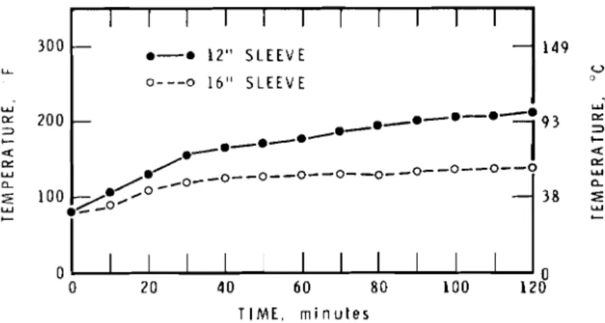
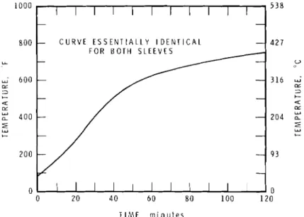
In test No. 1, using PVC, thermocouples were placed at the top of the sleeves and on each pipe 12 in. above the sleeve. Plots of the temperature - . - recordings are shown in Figure 16. In test No. 2 using ABS, thermocouple locations were altered so that on each sample thermocouples were located on the sleeve 1 in. above the concrete, 1 in. below the top of each sleeve, and 1 in. above the sleeve on the pipe itself. The plots of these data are shown in Figures 17 and 17(a).
Both tests ran the full 2-hour period with no indication that failure was near. In fact, the graphs in Figures 16, and 17 and 17(a) show that the temperature at the top of the sleeves was quite cool.
Examination of the samples after the test revealed that in test No. 1 a carboniferous ash had formed a seal across the diameter of the pipe
approximately 1 in. above the concrete. The ash was quite brittle and very thin in the middle. No signs of degradation were evident more than 3 in. above the concrete. Figure 18 shows the ash after the sleeve had been removed.
The ABS pipe in test No. 2 did not form the same type of ash because ABS is not an intumescent material, as is PVC. Examination of the samples after the test showed that the ABS had disintegrated with no residual ash to a point approximately 1 to 2 in. above the concrete. The next 2 inches of pipe revealed degradation in the form of char formation, brittleness, and some thinning in wall thickness. Above that level, the pipe was essentially untouched.
The results of the two tests of series C raises some interesting speculation. In both tests, the pipes remained intact and were virtually unblemished above the sleeves after a 2-hour test. In fact, pipe
destruction ended only a couple of inches above the top of the concrete slab. This situation would approach the optimum when a sleeve as thin as possible is used.
The same situation does not occur, however, when a section of pipe collapses over the top of the sleeve creating a seal. This creates a non-vented condition. Eventually the pipe becomes perforated creating a vented situation with ignition following shortly thereafter. This has been the case throughout the vertical test program. The difference in performance is probably attributable to a combination of two factors. Firstly, the sleeve wall thickness is greater and thus more heat is conducted to the pipe, and secondly, there is no insulating cushion of stagnant air.
The question of pipe wall thickness still remains for non-vented applications. Many non-vented applications would use thin-wall pipe,
probably with wall thickness of approximately 0.06 in. The pipe used in these tests had wall thicknesses of 0.17 and 0.15 in. for PVC and ABS respectively. Inspection of the pipe after the tests, however, showed that there was no deterioration in the pipe more than a few inches above the concrete slab, so using a sleeve of sufficient length should provide adequate protection.
In all test assemblies in the vertical mode, the space between the form and the sleeve was carefully packed with Fiberfrax to ensure that no leaks occurred around the assembly. Also, every sleeve had been anchored in place with a simple brace so that it would remain in place after the pipe burned away. Failure to do this once in test No. 3 forced premature termination of the test.
Finally, when using sleeves, it is desirable to have as little of the sleeve as possible in the fire compartment. For example, in the non-vented tests, the bottom of the sleeve was flush with the bottom of the concrete.
REFERENCES
1. Attwood, P.C. Study of Penetration of Walls by Plastic DWV Pipe, Progress Report. National Research Council of Canada, Division of Building Research, Internal Report 449, 1978.
2. Tamura, G.T. Computer Analysis of Smoke Movement in Tall Buildings. ASHRAE Transactions, Vol. 75, Part 11, 1969, p. 81-93.
3. Blumenkranz, J.J. U.S. Patent No. 3,726,050, April 10, 1973. 4. ibid.
5. Steele, Alfred, P.E. High Rise Plumbing Design. Miramas Publishing Co., Los Angeles, California, U.S.A., 1975, p. 90.
m k cd E al tY F: 0 C, .d m C, al rd i- k 7 n F: 0 .d C, o 7 k i C, m F:
3
x 3 P E al m2
al a .d a 4 cd al .d N k - d al V) v rd al z a .r( a a F: rd C, m al i- V] al2
.d L a, Q) V) F: .d.,-,
F: .d C.5
.z
.z .z
.5
aC d E E E E E E E E E 0 0 0 0 0 0 0 0 0 N N N N N N N P-4 3 A A A 3 3 A 4 a a..
al X A a A P E5
2
a al '+I:
g
al a i- rd d .d 0 C, k k cd F: +0 i- Ik9
c,i?
I+ F: a a m cd F: o aA .
4 U X al cd k L-
W m k al 3 al m -:\* al >-
A 3 A A d F : a a C, c d t Y .d k 0 cl al .,-,A C, C, v C, C,.d v C, 3 C, 3 Q ) m m m m m C , v , m a cd cd m a l a l Q ) a l a l Q ) r d a l a l Q ) o 5 W b i - i - i - i - A b i -al V) 7 a - d A F : c F : F : F : m F : F : P=
.d ad .d3:s
.d.,-,I5
.d
k al .d 7 6 0 m m7
> 3 n2
2
2
4
4
2
2
a-
-
-\*-
-
4-
-
-\*-
"\*-
-
-
A & A -
-
- -
-
&l &IX m M M
-
X X X X X "\*-
X X X-
-
-
4-
-
-
-
-
-1- -Y "\*- - -
"\*- -
-\* A A - I M M M 4 4 k al V) V ) u V ) u u U V) a m a 42 2 2 2 2 2
2
U 0 a 0 2 m a, .d k al V) t -. 4 N M b V ] a t - . C Q O A C, t ' c l t ' w t ' C, C, m m m m m m m m m al al a l a l a l i - $ b i - i - a l Q ) a l a l i- i - i - . d b k Q) V) C, mF: F: C
.d .d .d
TABLE 3
HORIZONTAL TEST ASSEMBLIES
Test Number
-
Series No. 4 Test 4 Test 5 Series No. 5 Test 1 Test 2 Test 3 Test 4 Test 5 Test 6 Series No. 6 Test 1 Material ~ -~ - ~ ABS PVC PVC ABS ABS ABS PVC ABS I ABS Assembly Description2-in. horizontal pipe into 2-in. vertical pipe; sleeved; and
insulated with %-in. Fiberfrax at wall penetration. Simple flapper. 1%-in. PVC, %-in. thick Fiberfrax insulation and 4-in. sleeve at wall penetration. Exposed end of sleeve equipped with 1190 gm. guillotine.
1%-in. PVC with 3-in. sleeve at wall penetration. Exposed side consisted of 5 x 10 x 8-in.
compartment with 1030 gm. guillotine on front side. Compartment filled with sand. As in Test 1.
As in Test 1. Guillotine wt. 1115 gm.
As in Test 1. Compartment filled with gypsum. (USG #1, Terra Alba, Hydrous Calcium Sulphate)
As in Test 1
As in Test 1, larger particle size sand.
Double flapper assembly. Pipe wrapped in %-in. Fiberfrax insula- tion inside sleeve. 4-in. long sleeve equipped with swivel flapper on each end. Flapper weights
approx. 530 gm. each. Vertical riser 1%-in. with single sanitary tee.
TABLE 3 (Cont'd) HORIZONTAL TEST ASSEMBLIES
Material
Number Assembly Description
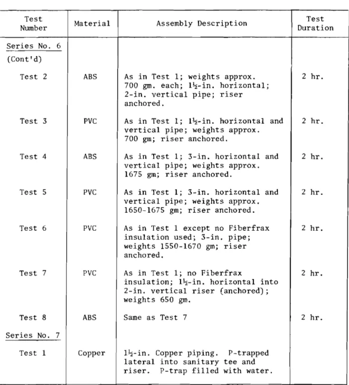
Test Duration Series No. 6 (Cont
'
d) Test 2 Test 3 Test 4 Test 5 Test 6 Test 7 Test 8 Series No. 7 Test 1 ABS PVC ABS PVC PVC PVC ABS CopperAs in Test 1; weights approx. 700 gm. each; 1%-in. horizontal; 2-in. vertical pipe; riser
anchored.
As in Test 1; 1%-in. horizontal and vertical pipe; weights approx. 700 gm; riser anchored.
As in Test 1; 3-in. horizontal and vertical pipe; weights approx.
1675 gm; riser anchored.
As in Test 1; 3-in. horizontal and vertical pipe; weights approx.
1650-1675 gm; riser anchored. As in Test 1 except no Fiberfrax insulation used; 3-in. pipe; weights 1550-1670 gm; riser anchored.
As in Test 1; no Fiberfrax
insulation; 1%-in. horizontal into 2-in. vertical riser (anchored) ;
weights 650 gm. Same as Test 7
l+-in. Copper piping. P-trapped lateral into sanitary tee and riser. P-trap filled with water.
2 hr. 2 hr. 2 hr. 2 hr. 2 hr. 2 hr. 2 hr.
-19- TABLE 4
VERTICAL TEST ASSEMBLIES
Test Duration 8 min. 53 min. Failure at 37 min. 15 min. 37 min. 2 hr. 1 hr. 1 hr. 27 min. 40 min. 2 hr. 2 hr. Test Number Series B Test 1 Test 2 Test 3 Test 4 Test 5 Test 6 Test 7 Test 8 Series C Test 1 Test 2 Material ABS PVC ABS ABS PVC PVC ABS ABS PVC ABS Assembly Description
4-in. pipe vertically mounted; 12-in. long sleeve at floor penetration.
Identical to Test 1
Identical to Test 1
Vertical flapper assembly; 12-in. sleeve with flapper on each end.
Identical to Test 4
9- x 17- x 20-in. compartment suspended from floor;
insulated; sleeved 3-in. pipe penetrated vertical side @
4S0 and floor @ 90°. Identical to Test 6
Identical to Test 7 except 4S0 sleeve insulated with %-in. Fiberfrax.
2 non-vented 2-in. pipe
penetrate floor; pipes sleeved 12 and 16 in. respectively. Identical to Test 1
4 I N C H C O N C R E T E SLAB VJITH O P E N I N G S F O R P I P E A S S E M B L I E S
I\\y
h\\\\\w
I I I I F L U E I I BURNER ( 4 ) E X P L O S I O N VE Figure 1Vertical Plumbing Assemblies Test Furnace
F I B E R F R A X H I N G E D FLAPPER P . . . .-.-., W l T H W E I G H T / 8 F l 0 E R F R A X L I N C A P P E D D W V P l P E W A L L C O N S T R U C T I O N 2 x 5 / 8 " TYPE X G Y P S U M 8 16 g o SHEET M E T A L Figure 2
Hinged Flapper Assembly Series No. 4, Test No. 4
G U I L L O T I N E W l T H W E I G H T C A P P D W V L E E V E W l T H b" I B E R F R A X I N S U L A T I O N ' E D PIPE Figure 3
Simple Guillotine Assembly Series No. 4, Test No. 5
S T E E L C O M P A R T M E N T 5 " r 1 0 ' ' x 8 " W A L L C O N S T R U C T I O N 2 x 5 1 . 8 " T Y P E X G Y P S U M 8 16 g o S H E E T S T E E L D W V P I P E Figure 4
Guillotine and Insulated Compartment Assembly
I
A S S E M B L Y:iplR.cKET
I Z O N T A LIN
EL
S L E E V E W A L L S E C T I O N S T E E L S H E E T " a) Side View F L A P P E R - l i 8 " S T E E L P L A T E W E I G H T S L E E V t F I B E R F R A X I N S U L A T I O N - P I P E b) End View Figure 5Double Flapper Mechanism a) Side View b) End View
(a) P r i o r t o T e s t
(b)
Approximate Time - 20 min.
( c > t = 28 min.
(dl t = 35 min.
F i g u r e 6
Time P r o g r e s s i o n o f Swivel F l a p p e r . Unexposed S i d e . a) P r i o r t o T e s t
b) Approximate Time - 20 min.
c ) t = 28 min. d) t = 35 min.
( e l t = 45 min. ( f t = 45 min. (g) A f t e r T e s t i s Over (h) A f t e r T e s t i s Over F i g u r e 6 (Cont 'd)
Time P r o g r e s s i o n of Swivel F l a p p e r . Unexposed S i d e (Contld) e) t = 45 min.
f ) t = 45 min.
g) A f t e r T e s t i s Over h) A f t e r T e s t i s Over
A B S A S S E M B L I E S P V C A S S E M B L I E S I I I I I A-30 O - - - o 1;" x 1;" A B S + j" FIBERFRAX -
8
- 1 1 o A - 3 1 A-A 1;" x 2" A B S + f " FIBERFRAX A - 3 3 0 - - - a 3" x 3" A B S t $" FI BERFRAX-
A-37 0-0 1:" x 2" ABS --
I 6 0 0 L W 5 4 0 0 + a LY 0 0 0 2 0 4 0 6 0 8 0 1 0 0 1 2 0 T I M E , m i n u t e s Figure 7(a)Air Temperature Inside Tee
a
0 2 0 4 0 6 0 8 0 1 0 0 1 2 0 T I M E , m i n u t e s
I I I I I
- A-32 A-A 1:'' x 1:" PVC +
:"
FIBERFRAX -A-34 0---• 3 " ~ 3" PVC + ~ " F I ~ E R F R A X - - A-35 0-0 3" x 3" pVC - A-36 o - - - o 1 t M x 2" p v c - - - 3 1 6 0 Y Oz 2 0 4 2 a Oz Y
P V C A S S E M B L I E S
5
0r
I I I I 0 20 40 60 80 100 120 0 TIME, minutes ABS A S S E M B L I E SI
I I II
_--a-W A-31 A-A 1'" z x 2" ABS + f" FI BERFRAX
+ A-33 0-- -0 3" x 3" ABS + f n FI BERFRAX
A-37 *-• If"
1
'04
"
TIME, minutes
Figure 7(b)
T I M E , m i n u t e s P V C A S S E M B L I E S
A B S A S S E M B L I E S
I I I I I
- A-30 o---o 1'" x 15" A B S + f " FIBERFRAX A - 3 1 A-A 1;" x 2" A B S + f " FIBERFRAX
-
A-33 0---a 3" x 3' A B S + f" FIBERFRAX
- A-37 O-• If" x 2 " A B S
- - I I I I I 3 1 6 2 0 4 6 0 0 LL W 5 4 0 0 C a m W 0 0 0 2 0 4 0 6 0 8 0 1 0 0 1 2 0 T I M E . m i n u t e s I I I I I
- A-32 A-A 1:" x 1:" PVC + I" FIBERFRAX - A-34 0---a 3" x 3" PVC + $" FIBERFRAX - - A-35 0-• 3 " x Y P V C - A-36 o---o l + " x 2" pVC
-
--
Figure 7 ( c ) aTemperature
-
Exterior of Tee0---0
---,,---
o---o---O-- -o.---u--o---n5
- ~ - ~ - - f j 9 3C i?=@38- , - g ~ * P I - * ~ * - -
0 I I I I I 0
I I I - - - 6 - ---m---m---m 5 - 1 FURNACE CURVE - 2 P l P E INSIDE FURNACE
3 LATERAL PIPE UNEXPOSED SIDE OF WALL 5 VERTICAL P l P E 3' ABOVE TEE
6 A I R TEMP I N S I D E VERTICAL PIPE. - 3' ABOVE TEE 7 A I R TEMP INSIDETEE 0 0 0 20 4 0 6 0 T I M E . m i n Figure 8
Temperature Record for 1%" Copper Pipe. Test A-38
118" S T E E L P L A T E F L A P P E R H I N G E A N D S U P P O R T
'
E X P O S E D S I D E1;
W E I G H T - T S L E E V E S U P P O R T S i 4 " C O N C R E T E S L A B 2 4 GA S T E E L S L E E V E - 4 " P I P E ( A B S OR P V C ) Figure 9Back View - Top o f F l a p p e r Assembly A f t e r T e s t B-5 (b) S i d e View - T e s t B-5 ( c ) View o f Exposed P o r t i o n - A f t e r T e s t B-5 ( d l
C a r b o n i f e r o u s PVC Ash Formed Above Top F l a p p e r
F i g u r e 10
Apparatus and P i p e A f t e r T e s t
( a ) Back View - Top o f F l a p p e r Assembly A f t e r T e s t B-5 (b) S i d e View - T e s t B-5
( c ) View o f Exposed P o r t i o n - A f t e r T e s t B-5
, l . C . 9
kJ
S C A L E :" : I " I A I A T E R I A L . 3" P L A S T I C P I P En
P L C OF; A B C S I - E E V E S : 8 " S H E E T S T E E L 1 8 g a 5 ' r T C 8 4 " C O N C R E T E D E N S E A S B E S T O S B O A R D W R A P P E D I N 1" F I B E R F R A X , M O U N T E D O N L I R O N F R A M E 20" T C 2 Figure 11(a)
Assembly Before Exposure Compartment A f t e r T e s t -
F r o n t Panel Removed
( c ) Cd)
S l e e v e Through Concrete F l o o r S e c t i o n o f C o l l a p s e d Pipe A f t e r T e s t Viewed From Above A f t e r T e s t Compared t o O r i g i n a l Pipe (3" PVC)
F i g u r e 1 2 V e r t i c a l T e s t B-6 ( a ) Assembly Before Exposure
(b) Compartment A f t e r T e s t
-
Front Panel Removed( c ) S l e e v e Through Concrete F l o o r Viewed From Above A f t e r T e s t
T I M E , m i n u t e s
Figure 13(a)
TIME, m i n u t e s
Figure 1 3 ( b )
N O M I N A L 2 " P V C D W V P I P E 2 4 G A U G E S T E E L S L E E V E E X T E N T O F D E S T R U C T I O N C O N C R E T E F i g u r e 15
Smoke From S t a c k E a r l y i n T e s t P i p e F o l d i n g Over C r e a t i n g a S e a l P i p e i s S t a r t i n g t o Sag
( c l ( d l
Hole Forming a t Top o f S l e e v e
A f t e r Approximately 1 h r Same a s (C) Viewed From O t h e r S i d e F i g u r e 14
V e r t i c a l T e s t B-7
( a ) Smoke From S t a c k E a r l y i n T e s t P i p e i s S t a r t i n g t o Sag (b) P i p e F o l d i n g Over C r e a t i n g a S e a l
( c ) Hole Forming a t Top o f S l e e v e A f t e r Approximately 1 h r (d) Same a s ( c ) Viewed From O t h e r S i d e
a) Temperature of ABS Pipe 1" Above Sleeves I I I I I I I I I I 300 - 0-0 12" SLEEVE - 149 LL -.,.-• U 0---o 16" SLEEVE
/./.--•
w 200 C I- a - O - ~ O ~ ~ o ~ - o - - O - - O - - O a u? w OI IY a a C C 0 20 4 0 60 80 100 120 TIME. m i n u t e s 149 V 300 Vb) Temperature at Top of Sleeves vs Time
1 1 1 1 1 1 1 1 1 1 1 - 0-0 12" SLEEVE
-
0 - - - 0 16" SLEEVE Figure 17 Vertical Test C-2a) Temperature of ABS Pipe
I"
Above Sleevesb) Temperature at Top of Sleeves vs Time
W W = 200 - 3 C a w w a C 0 20 40 60 8 0 100 120 T I M E , m i n u t e s
a) Temperature o f PVC Pipe 12" Above Sleeves 300 LL 200 3 C 4 @L W l o o W C 0
b) Temperature at Top of Sleeves vs Time
I I I I I - N O T E : D A T A E S S E N T I A L L Y - - I D E N T I C A L F O R B O T H P I P E S
-
-
- *-*-*-.-*-*-*-*-*-*-*-*-• T . C . 3 & T . C . 8 I I I I I 300 LL W = 2 0 0 - 3 C a P: W a Figure 16 Vertical Test C-1a) Temperature of PVC Pipe 12" Above Sleeves b) Temperature at Top o f Sleeves vs Time
149 U W 9 3 5 C 4 rx W a - 3 8
5
C 0 20 40 6 0 8 0 100-
I I I I I - 0-0 T . C . 4 16" S L E E V E - 0---• T . C . 6 12" S L E E V E-
0 149 o W 9 3 5 C 4 100 - ~ ' ~ o - o - o ~ o - o - ~ - O - O - O ~ 385
120 T I M E , m i n u t e s *---*--- *---)---• a: ,*---.---- -
.---*--I
:
C C 0 I I 20 4 0 6 0 8 0 100 120 0 T I M E , m i n u t e sI I I I I I I I I I I - - - C U R V E E S S E N T I A L L Y I D E N T I C A L - F O R B O T H S L E E V E S - - - - - - - I I I I I I I 0 0 0 2 0 40 60 8 0 100 120 T I M E , m i n u t e s
Temperature of Sleeve 1" Above Concrete
Figure 17(a) Vertical Test C-2
Figure 18
Residual Ash - 2" PVC Non-Vent ed