HAL Id: hal-00298591
https://hal.archives-ouvertes.fr/hal-00298591
Submitted on 25 Jul 2006HAL is a multi-disciplinary open access
archive for the deposit and dissemination of sci-entific research documents, whether they are pub-lished or not. The documents may come from teaching and research institutions in France or abroad, or from public or private research centers.
L’archive ouverte pluridisciplinaire HAL, est destinée au dépôt et à la diffusion de documents scientifiques de niveau recherche, publiés ou non, émanant des établissements d’enseignement et de recherche français ou étrangers, des laboratoires publics ou privés.
Design of an automatic multiple launcher for expendable
probes
G. Zappalü, F. Reseghetti, G. M. R. Manzella
To cite this version:
G. Zappalü, F. Reseghetti, G. M. R. Manzella. Design of an automatic multiple launcher for ex-pendable probes. Ocean Science Discussions, European Geosciences Union, 2006, 3 (4), pp.997-1009. �hal-00298591�
OSD
3, 997–1009, 2006
An automatic multiple launcher for
expendable probes G. Zappal `a et al. Title Page Abstract Introduction Conclusions References Tables Figures J I J I Back Close
Full Screen / Esc
Printer-friendly Version Interactive Discussion
EGU Ocean Sci. Discuss., 3, 997–1009, 2006
www.ocean-sci-discuss.net/3/997/2006/ © Author(s) 2006. This work is licensed under a Creative Commons License.
Ocean Science Discussions
Papers published in Ocean Science Discussions are under open-access review for the journal Ocean Science
Design of an automatic multiple launcher
for expendable probes
G. Zappal `a1, F. Reseghetti2, and G. M. R. Manzella2
1
CNR-IAMC Section of Messina, Messina, Italy
2
ENEA-CRAM, S. Teresa, Pozzuolo di Lerici, Italy
Received: 10 May 2006 – Accepted: 17 July 2006 – Published: 25 July 2006 Correspondence to: G. Zappal `a ([email protected])
OSD
3, 997–1009, 2006
An automatic multiple launcher for
expendable probes G. Zappal `a et al. Title Page Abstract Introduction Conclusions References Tables Figures J I J I Back Close
Full Screen / Esc
Printer-friendly Version Interactive Discussion
EGU Abstract
A main goal of a ships of opportunity program is the provision of near real time temper-ature profiles. The use of expandable probes allows the reduction of costs, in compari-son to usual scientific cruises. A major cost effectiveness can be achieved by using an automated multiple launcher, that can be used with a minimum personnel effort. A mul-5
tiple launcher, developed in the framework of the Mediterranean Forecasting System – Toward Environmental Prediction, allows to collect eight temperature profiles, with a sampling strategy that can be monitored automatically by means of a software. The data acquisition system is controlled internally in all functionalities, and data can be transmitted by GSM or satellite telephone systems.
10
1 Introduction
A Ships Of Opportunity Program (SOOP) was established in the Mediterranean in September 1999, on behalf of the EC funded project Mediterranean Forecasting Sys-tem – Pilot Project (MFS-PP, Pinardi et al., 2003). Temperature-XBT profiles were collected along six transects crossing the Western and the Eastern basins from North 15
to South and one transect crossing the whole sea from East to West. These tran-sects were designed to specify, in each of the sub-basins (the Algero-Provenc¸al, the Tyrrhenian, the south Adriatic, the Ionian and the Levantine), the variability of the main circulation features ( ¨Ozsoy et al., 1991;1993; POEM Group, 1992; Hecht and Gertman, 2001, Fusco et al, 2003; Millot and Taupier-Letage, 2005; Zodiatis et al., 2005). 20
The initial aim of the study was the continuous and regular sampling of the Mediter-ranean upper thermal structure using XBT measurements. This included also the de-velopment of quality criteria for data collection and management, and the improvement of near real time data exchange capabilities. The technology was the same as that used in the international SOOP program (Smith et al., 2000): Sippican XBTs for data 25
sub-OSD
3, 997–1009, 2006
An automatic multiple launcher for
expendable probes G. Zappal `a et al. Title Page Abstract Introduction Conclusions References Tables Figures J I J I Back Close
Full Screen / Esc
Printer-friendly Version Interactive Discussion
EGU sampled by the ARGOS software, and coded for transmission on the GTS (Global
Telecommunications System) in the BATHY format (AODC, 1999; AODC 2001; Cook and Sy, 2001, Manzella et al., 2003).
During the years, the data collection strategy (including sampling design, technolo-gies for data collection and transmission) was tested and implemented, as well as the 5
near-real time (NRT) data management (including NRT QC, and data access). Data transmission was achieved using a normal GSM phone/modem for Internet connec-tion. The edf – full resolution Sippican files were compressed and sent attached to an e-mail. This simple improvement was made possible by the GSM coverage avail-able in the Mediterranean region. Transmitting the full resolution profiles required to 10
change the quality control (QC) procedures. The software developed was based on Medar-Medatlas protocols (MedAtlas Group, 1994) and contained all the steps of the delayed mode quality control: gross range check, position control, elimination of spikes, re-sampling at 1-m interval, Gaussian smoothing, general malfunction control, compar-ison with climatology. Two visual checks were added at the beginning and at the end 15
of the QC procedure, in order to detect the end of a given profile and look at the overall consistency of the profiles (Manzella et al., 2003).
The cost of the observations performed through ships of opportunity and XBT is rel-atively high (although less than the costs of research cruises), and is not sustainable by a research community. However, some technological implementations could make 20
a SOOP more cost effective. This can be achieved by the selection of tracks, the de-velopment of multi-parametric observation systems and the dede-velopment of automated data collection systems. The main requirements of the SOOP were defined in MFS-PP. An ideal sampling program is based on four goals:
– provide repetitive measurements along transects from coast to coast,
25
– the transects must cross significant dynamical features of the circulation, – the sampling distance should resolve, as well as possible, the mesoscale,
OSD
3, 997–1009, 2006
An automatic multiple launcher for
expendable probes G. Zappal `a et al. Title Page Abstract Introduction Conclusions References Tables Figures J I J I Back Close
Full Screen / Esc
Printer-friendly Version Interactive Discussion
EGU – the technologies for data collection must be robust and simple, to be used on
ships of opportunity, also by ship personnel.
Automated systems have been developed in Japan and USA. For example, the TSKA AL-12 multiple launcher can be loaded with 12 XBT probes that can be launched fol-lowing some established criteria. The launcher has to be linked to a personal computer 5
and Sippican data acquisition card. The TSKA is formed by revolving tubes, that are positioned in the launching position by an electric engine. It was used at the end of MFS-PP, with the launching system managed by a software allowing the selection of the probe type and the launch at defined sampling intervals. The conclusion was that the machine is robust to all weather conditions and reliable, but is hard to handle, heavy 10
and needs continuous surveillance.
On the basis provided by this experience, two possible options were hypothesized for the development of a multiple launcher:
– a series of tubes revolving in circular – a series of tubes along one or two lines
15
The second solution was selected, since it was minimising the number of elements in movements.
This paper presents some background information on technology used in SOOP and the development of a multiple launcher.
2 The Expendable Bathy-Thermographs (XBT)
20
An XBT probe has the shape of a small missile, contained in a cylindrical plastic can-ister. A precision NTC thermistor is enclosed in the zinc nose, while the copper wire assuring the connection to the measuring system is contained in two spools, one in the plastic body of the probe and the other one in the canister that also hosts on its back the electrical connections towards the data acquisition system
OSD
3, 997–1009, 2006
An automatic multiple launcher for
expendable probes G. Zappal `a et al. Title Page Abstract Introduction Conclusions References Tables Figures J I J I Back Close
Full Screen / Esc
Printer-friendly Version Interactive Discussion
EGU When the XBT is launched, it falls down into the sea and the wire in the probe starts
dereeling. The wire dereels also from a spool within the probe canister, compensating the movement of the ship and allowing the probe to freefall from the sea surface. The system uses the water as a ground connection: when the electrode within the nose of the probe makes contact with the water, the circuit is closed and the value of voltage 5
is telemetered to the shipboard data processing equipment. When the probe reaches the desired depth, or the wire breaks (on ship-side or on probe-side), the profile is completed and the system can be prepared for another launch. The nominal accuracy of the thermistor is ±0.1◦C. The depth is estimated as a function of time using the formula developed by the manufacturer Z (t)=At–Bt2.
10
3 Standard instrumental apparatus in MFS-TEP
The standard acquisition system consists of a hand launcher (LM-3A), a read-out MK21 (or MK12) card installed in a PC with ISA slot, and an interface box.
The LM-3A launcher provides portability, allows the selection of the launch position, and reduces the interference due to the electrical apparatus on the ship. The ISA card 15
can be upgraded to USB with the addition of a particular kit. MK21 uses DSP technol-ogy for onboard processing and buffered I/O for operation with operating system such as Windows 98, Win2000, ME, and XP. Data collection is controlled by the MK21 and the buffered I/O stores the data until it can be read in by the operating system. MK21 has a flash memory for in-system programming to give users the flexibility to add newly 20
developed probe capability and firmware upgrades. The computer performs system diagnostics and plaunch tests, and indicates that the probe is ready for launch. It re-ceives probe data during the probe descent, displays and stores them. Data are trans-lated in ASCI text format. The MK21 Windows Software has auto GPS (NMEA 0813) input capability, selectable IGOSS and other fall rate coefficients, and post-processing 25
options. The sampling rate is 10 Hz, which implies a vertical resolution of about 65 cm, an overall temperature accuracy of ±0.2◦C, and a temperature resolution of ±0.01◦C.
OSD
3, 997–1009, 2006
An automatic multiple launcher for
expendable probes G. Zappal `a et al. Title Page Abstract Introduction Conclusions References Tables Figures J I J I Back Close
Full Screen / Esc
Printer-friendly Version Interactive Discussion
EGU The launcher is connected to the MK21 card through a connection box, where the
system ground is connected to the seawater ground from a lug on the outside of the box to some metal part of the hull of the ship. The seawater ground has to be electrically clean and as pure as possible. The connection should be protected from corrosion and vibration, and its resistance should measure less than 100 Ohm from the connection 5
box to the seawater. The radio-transmission can produce hard interference with the data acquisition and may interrupt the XBT data, which will cause large spikes and noise on the recorded sequence of resistance values. Other troubles may occur when wind or occasional random movement induces a contact between the wire and the hull: in this case large spikes appear.
10
The XBT voltage readings were converted to temperatures through several steps. First, a Sippican XBT Controller transmitted hexadecimal voltage values (representing XBT thermistor measurements) to a shipboard PC. Second, the XBT program con-verted those hexadecimal voltage equivalents into resistance, and then into tempera-ture (◦C), in the following manner:
15
1. Convert hexadecimal value into decimal value.
2. Convert decimal value to (V) voltage (i.e., V=10.0×decimal value/4096) (volts). 3. Convert (V) voltage into (R) resistance measured in ohms (i.e., R=18094–
1490.1×V) (ohms).
4. Convert (R) resistance into (T) temperature measured in ◦C (i.e., T=– 20
273.15+{1/[A+(B*ln R)+C*(ln R)3)]}, where: A=1.29502*10−3, B=2.34546*10−4, and C=9.9434*10−8).
Steinhart and Hart (1968) first proposed such a logarithmic equation, which is an em-pirical expression that has been recognised to be the best mathematical expression for resistance-temperature relationship of NTC thermistors and probe and assemblies. 25
The constants were determined empirically from laboratory tests of XBT thermistors (Georgi et al., 1980).
OSD
3, 997–1009, 2006
An automatic multiple launcher for
expendable probes G. Zappal `a et al. Title Page Abstract Introduction Conclusions References Tables Figures J I J I Back Close
Full Screen / Esc
Printer-friendly Version Interactive Discussion
EGU
4 The new system
The new system is an integrated set of mechanical and electronic hardware and soft-ware programs giving the user the maximum of flexibility
4.1 The mechanical hardware
Heart of the system is a launch tube, built in AISI 316 steel, in which the probe is fitted 5
with its envelope. An upper cap, holding the electrical connections of the probe, closes the launch tube; opening the lower door the probe is released and falls into seawater.
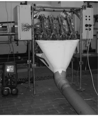
Two pneumatic cylinders control the door: a small one keeps it closed, a bigger one moves it. In the actual MFS-VOS design, the system assembles on a frame eight launch tubes with their pneumatic actuators; two watertight boxes host respectively the 10
electro-pneumatic valves feeding the cylinders and the computerized control system (Fig. 1).
4.2 The control computer hardware and software 4.2.1 The electronic hardware
All operations are coordinated by an industrial grade computer, based on IEEE 696 15
compliant boards, interfaced with GPS, data acquisition and communication devices. Both analog and digital interfaces are available to collect data coming from the most various devices (passive and active expendable probes, meteo sensors...).
Remote communications are performed using a GPRS modem with an embed-ded TCP-IP stack; a serial port is available to connect other communication de-20
vices (e.g. satellite modems), but also other communications systems could be used (e.g. satellite phones).
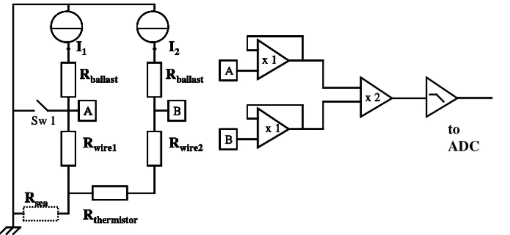
A balanced source circuit (Fig. 2) was designed to interface standard passive tem-perature probes with 12 or 16 bit Analog to Digital Converters.
OSD
3, 997–1009, 2006
An automatic multiple launcher for
expendable probes G. Zappal `a et al. Title Page Abstract Introduction Conclusions References Tables Figures J I J I Back Close
Full Screen / Esc
Printer-friendly Version Interactive Discussion
EGU Two equal currents are injected in both the wires coming from the probe and the
potentials VA and VB are measured; the circuit is closed by the sea water; the switch SW1 (a relay contact) allows to test the continuity of the probe circuit before the launch. To avoid any perturbation to the measurement, a multiple stage amplifier was used to adapt the signal coming from the probe to the need of the ADC; the circuit was built 5
using high quality precision instrumentation amplifier ICs. The first stage uses unity gain configuration, having high input and low output impedance; the second stage is a differential amplifier with gain=2; the third stage is a low output impedance low-pass filter with gain=1 and ft=40 Hz. Ten times a second, the mean of 16 (VB-VA) measurements is calculated; the resistance of the thermistor is obtained using Ohm’s 10
law, or, better, using the regression coefficients obtained after calibration of the circuit against a set of standard high precision resistors. The measured temperature is finally obtained using the standard formula by Steinhart and Hart (1968)
4.2.2 The software
Two software sets were developed, able to manage 96 launch events. 15
Launch options are:
• northern than a defined latitude • southern than a defined latitude • eastern than a defined longitude • western than a defined longitude 20
• far from a previous station • at GPS time
OSD
3, 997–1009, 2006
An automatic multiple launcher for
expendable probes G. Zappal `a et al. Title Page Abstract Introduction Conclusions References Tables Figures J I J I Back Close
Full Screen / Esc
Printer-friendly Version Interactive Discussion
EGU Collected data are locally stored and can be transmitted as e-mails. A local control
program was written in Microsoft Compiled Basic v. 7.1 with routines in Assembly Lan-guage, running in Datalight DOS environment. This program, executed on the launcher control computer is able to control all the launcher functions, i.e. real time and position acquisition, comparison against set points-times, launch, data acquisition and trans-5
mission, ancillary functions.
Every hour, a “sequence manager” starts a macro-command sequence, that can be different for each time and is remotely reprogrammable; new releases of the software and of the sequences are uploadable to the station without suspending its normal ac-tivity. The macro-commands enable to manage the data acquisition and transmission, 10
the mission programming, the station hardware and the measuring instruments. The entire system can be connected to a computer (local laptop or remote desktop), using a remote control program, written in Microsoft Visual Basic, running in Windows environment. This program enables to set up all the launcher functionalities, trans-fer files to and from the launcher, and, if needed, to take control of all the launcher 15
operations, including the time-position acquisition and comparison.
5 Conclusions
The development of a multiple launcher improves the cost effectiveness of an opera-tional observing system. Compared to the existing hand launcher system, the improve-ment is evident. The multiple launcher allows to automatically launch a certain number 20
of XBTs without human intervention. With respect to the other multiple launcher tested before, the TSKA, the one developed in this project is lighter, and has a minor amount of electric or mechanic components, that makes the reliability of the entire system higher. Another advantage of this multiple launcher is the capability to be remotely managed, although this facility was not yet tested. The automatic multiple launcher 25
was tested in laboratory and during a short cruise on ship of the Italian Hydrographic Institute. The first results obtained confirm the instrument reliability and open to further
OSD
3, 997–1009, 2006
An automatic multiple launcher for
expendable probes G. Zappal `a et al. Title Page Abstract Introduction Conclusions References Tables Figures J I J I Back Close
Full Screen / Esc
Printer-friendly Version Interactive Discussion
EGU developments.
Acknowledgements. The activity is funded in the frame of the MFSTEP project, 5th EU FP. The authors acknowledge the support provided by N. Pinardi and G. Coppini. The work of technicians during these years have provided the necessary information for the design. We wish to thank A. Baldi and F. Conte (ENEA) for their technical support.
5
References
AODC: Guide to MK12 – XBT System (Including Launching, returns and faults). Australian Oceanographic Data Centre (AODC), METOC Services, 1–63, 1999.
AODC: Expendable Bathythermographs (XBT) delayed mode. Quality control manual. Aus-tralian Oceanographic Data Centre (AODC), Data Management Group, Technical Manual
10
1/2001, 1–24, 2001.
Cook, S. and Sy, A.: Best guide and principles manual for the Ships Of Opportunity Program (SOOP) and eXpendable BathyThermograph (XBT) operations. Prepared for the IOC-WMO-3rd Session of the JCOMM Ship of Opportunity Implementation Panel (SOOPIP-III), 28–31 March, 2000, La Jolla, California, USA, 1–26, 2001.
15
Fusco, G., Manzella, G. M. R., Cruzado, A., Gacic, M., Gasparini, G. P., Kovacevic, V., Millot, C., Tziavos, C., Velasquez, Z., Walne, A., Zervakis, V., and Zodiatis, G.: Variability of mesoscale features in the Mediterranean Sea from XBT data analysis, Ann. Geophys., 21, 21–32, 2003. Georgi, D. T., Dean, J. P., and Chase, J. A.: Temperature calibration of expendable
bathy-thermographs, Ocean Eng., 7, 491–499, 1980.
20
Hecht, A. and Gertman, I.: Physical features of the eastern Mediterranean resulting from the integration of POEM data with Russian Mediterranean cruises. Deep-Sea Res. I, 48, 1847– 1876, 2001.
Manzella, G. M. R., Scoccimarro, E., Pinardi, N., and Tonani, M.: Improved near real time data management procedures for the Mediterranean ocean Forecasting System - Voluntary
25
Observing Ship program. Ann. Geophys., 21, 21-32, 2003.
Millot, C. and Taupier-Letage, I.: Additional evidence of LIW entrainment across the Alge-rian Basin by mesoscale eddies and not by permanent westward-flowing vein, Progress Oceanogr., 231–250, 2005.
OSD
3, 997–1009, 2006
An automatic multiple launcher for
expendable probes G. Zappal `a et al. Title Page Abstract Introduction Conclusions References Tables Figures J I J I Back Close
Full Screen / Esc
Printer-friendly Version Interactive Discussion
EGU
¨
Ozsoy, E., Hecht, A., ¨Unl ¨uata, ¨U., Brenner, S., Sur, H. ., Bishop, J., Latif, M. A., Rozentraub, Z., and Ouz, T.: A synthesis of the Levantine Basin circulation and hydrography, 1985–1990, Deep-Sea Res., 40, 1075–1119, 1993.
Pinardi, N., Allen, I., Demirov, E., DeMey, P., Korres, G., Lascaratos, A., LeTraon, P. Y., Maillard, C., Manzella, G., and Tziavos, C.: The Mediterranean ocean Forecasting System: first phase
5
of implementation (1998–2001), Ann. Geophys., 21, 3–20, 2003.
POEM Group: General Circulation of the Eastern Mediterranean Sea, Earth Sci. Rev., 32, 285–309, 1992.
Smith, N. R., Harrison, D. E., Bailey, R., Delcroix, T., Hanawa, K., Keely, B., Meyers, G., Molinari, B., and Roemmich, D.: The role of XBT sampling in the ocean thermal network,
10
OCEANOBS St Raphael, 18–22 October, 1999.
Steinhart, J. S. and Hart, S. R.: Calibration curves for thermistors, Deep-Sea Res., 15, 497– 503, 1968.
Zodiatis, G., Drakopoulos, P., Brenner, S., and Groom, S.: Variability of the Cyprus warm core Eddy during the CYCLOPS project, Deep Sea Res., II 52, 2897–2910, 2005a.
OSD
3, 997–1009, 2006
An automatic multiple launcher for
expendable probes G. Zappal `a et al. Title Page Abstract Introduction Conclusions References Tables Figures J I J I Back Close
Full Screen / Esc
Printer-friendly Version Interactive Discussion
EGU
Fig. 1 - The multiple launcher with the electro-valves box (left) and the electronics box (right), on the floor the air compressor (left) and the red pipe connected to the funnel to drive probes outboard
Fig. 1. The multiple launcher with the electro-valves box (left) and the electronics box (right), on the floor the air compressor (left) and the red pipe connected to the funnel to drive probes outboard.
OSD
3, 997–1009, 2006
An automatic multiple launcher for
expendable probes G. Zappal `a et al. Title Page Abstract Introduction Conclusions References Tables Figures J I J I Back Close
Full Screen / Esc
Printer-friendly Version Interactive Discussion EGU to ADC A B Rsea A Rwire1 Rwire2 Rthermistor I1 I2 Rballast Rballast Sw 1 x 2 B A x 1 x 1 A B Rsea A Rwire1 Rwire2 Rthermistor I1 I2 Rballast Rballast Sw 1 A B Rsea A Rwire1 Rwire2 Rthermistor I1 I2 Rballast Rballast Sw 1 A B Rsea A Rwire1 Rwire2 Rthermistor I1 I2 Rballast Rballast A B Rsea A Rwire1 Rwire2 Rthermistor I1 I2 Rballast Rballast A BB Rsea A Rwire1 Rwire2 Rthermistor I1 I2 Rballast Rballast Sw 1 x 2 B A x 1 x 1 x 2 B A x 1 x 1 x 2 x 2 B A x 1 x 1 B A x 1 x 1 B A x 1 x 1 B A x 1 x 1
Fig. 2 - The schematics of the probe interface board
Fig. 2. The schematics of the probe interface board.