RESEARCH OUTPUTS / RÉSULTATS DE RECHERCHE
Author(s) - Auteur(s) :
Publication date - Date de publication :
Permanent link - Permalien :
Rights / License - Licence de droit d’auteur :
Bibliothèque Universitaire Moretus Plantin
Institutional Repository - Research Portal
Dépôt Institutionnel - Portail de la Recherche
researchportal.unamur.be
University of Namur
Facile fabrication of lightweight porous FDM-printed polyethylene/graphene
nanocomposites with enhanced interfacial strength for electromagnetic interference shielding
Jing, Jingjing; Xiong, Yu; Shi, Shaohong; Pei, Haoran; Chen, Yinghong; Lambin, Philippe
Published in:
Composites Science and Technology DOI:
10.1016/j.compscitech.2021.108732
Publication date: 2021
Document Version
Early version, also known as pre-print
Link to publication
Citation for pulished version (HARVARD):
Jing, J, Xiong, Y, Shi, S, Pei, H, Chen, Y & Lambin, P 2021, 'Facile fabrication of lightweight porous FDM-printed polyethylene/graphene nanocomposites with enhanced interfacial strength for electromagnetic interference shielding', Composites Science and Technology, vol. 207, 108732.
https://doi.org/10.1016/j.compscitech.2021.108732
General rights
Copyright and moral rights for the publications made accessible in the public portal are retained by the authors and/or other copyright owners and it is a condition of accessing publications that users recognise and abide by the legal requirements associated with these rights. • Users may download and print one copy of any publication from the public portal for the purpose of private study or research. • You may not further distribute the material or use it for any profit-making activity or commercial gain
• You may freely distribute the URL identifying the publication in the public portal ? Take down policy
If you believe that this document breaches copyright please contact us providing details, and we will remove access to the work immediately and investigate your claim.
Composite Sciences and Technology 207 (2021) 108732.1-10. DOI: 10.1016/j.compscitech.2021.108732
Facile Fabrication of Lightweight FDM-Printed
Polyethylene/Graphene Nanocomposites with Enhanced
Interfacial Strength for Electromagnetic Interference Shielding
Jingjing Jing a, Shaohong Shi a, Haoran Pei a, Yu Xiong a, Yinghong Chena, PhilippeLambin b
a State Key Laboratory of Polymer Materials Engineering, Polymer Research Institute
of Sichuan University, Chengdu 610065, China
b Département de Physique, Université de Namur, 61 Rue de Bruxelles, B-5000
Namur, Belgium
Abstract
In order to shield the massive electromagnetic perturbations and meet the more and more stringent requirement for high-end electronic equipment, development of diverse, lightweight and high-performance electromagnetic interference (EMI) shielding materials is urgent but still challenging. Herein, the combination of fused deposition modeling (FDM) 3D printing, ball milling and microwave (MW) irradiation technology is proposed to fabricate exfoliated graphene nanoplatelets (GNPs) incorporated liner low density polyethylene (LLDPE) nanocomposite parts with porous and complex geometry structure. FDM 3D printing possesses high flexibility for structure design, which can significantly broaden the application of
materials in various fields. Benefiting from design of a unique porous lamellar structure, the printed LLDPE/GNPs nanocomposite parts can achieve a prominent EMI shielding effectiveness (SE) of ~32.4 dB (with thickness-normalized specific EMI SE (SSE/t) of 318 dB cm2 g−1) in the range of 8.2-12.4 GHz. This remarkable
characteristics is due to internal multiple reflections and absorption. The use of MW irradiation technology improves mechanical properties, especially for the interfacial bonding strength between filaments. More importantly, this strategy is highly beneficial for the fabrication of lightweight EMI shields with tailorable and optimized shape/structure, which could be expected to be applied in aerospace fields, portable electronic devices, smart devices and so on.
Keywords: fused deposition modeling, 3D printing, graphene nanoplatelets,
microwave irradiation, EMI shielding
Introduction
With the development of the 5G communication technology based on the gigahertz electromagnetic (EM) waves, the electromagnetic pollution issue, which is caused by the corresponding exponential growth of electronic devices, is receiving more and more attention. ot only does it affect the normal functioning and lifetime of the electronic devices but also it threatens the human health [1-4]. Thus, high-efficiency EMI shielding materials are more urgently required to overcome the above challenges than ever [5-8]. As it is well known, metal-based shields are the most widely used EMI protectors. However, the metallic shields have some drawbacks such
as high density, easy corrosion under air exposure, poor flexibility and relatively inferior processability [9, 10]. In addition, they reflect back most of the incident electromagnetic radiations, increasing thereby the EM pollution around them. Meanwhile, nowadays, the development of high-end EMI shielding coating in many fields --including wearable clothing devices, portable electronic equipment, aircraft and aerospace facility-- increasingly relies on light weight, flexibility and environmental stability of material. Therefore, conductive polymer composites (CPCs) are becoming promising candidates to be employed as EMI shields, due to their specific advantages of easy functionalization, facile design, excellent moldability and some other intrinsic properties of the polymer matrix such as lightweight, low-cost and corrosion resistance [11-16]. Obviously, effective reduction of weight, efficient utilization of energy and materials are crucial to practical EMI shielding applications in various areas [5, 17].
In general, lightweight CPCs can be obtained by adopting various preparation methods such as freeze-drying method [18, 19], compression molding [20-22] and foaming process [23, 24]. In these processes, however, the conductive network distributed in the polymer matrix is hard to be controlled with the possible consequence of lowering the effective conductivity [12, 25]. For instance, lightweight PEI/CNT foams prepared via a sinter molding and further supercritical CO2 (scCO2)
foaming, demonstrate an EMI shielding efficiency (SE) ranging from 35.3 dB to 5.5 dB with decreasing density from 1.27 to 0.61 g/cm3 [23]. However, it is found that the
applications. On the other hand, the aforementioned technologies are also facing great challenges in fabricating architectures with complex geometric structure. This would surely restrict their applications in some special fields. More recently, the 3D printing technology, also known as additive manufacturing (AM), has attracted more and more attention. Among the 3D printing technologies, fused deposition modeling (FDM) is currently one of the most frequently applied technologies in practice [26-28]. FDM 3D printing involves a filament-based printing process, during which the filament is first fed into a heating nozzle, melted and then extruded out of the nozzle. Finally, the extruded melts are deposited onto a build plate to generate a three-dimensional structure in a layer-by-layer process [29]. Due to the high designing and manufacturing flexibility [30-32] of FDM 3D printing technology, it has been receiving more and more attention and applied to fabricate the EMI shields for lightweight and diversity purposes [33-35]. However, less work has been involved in investigating the effects of the printing structure on the EMI SE. Particularly, it is worth noting that good-quality interfaces can induce beneficial multiple reflections of the EM wave in the interior of the 3D printed part [36].
However, the poor interlaminar bonding strength still remains a challenge for the 3D printed parts. In order to address this issue, specific heat treatments has been reported in several studies [37, 38]. As we know, in the conventional heating mode, a material is generally heated from outside to inside through radiation, conduction and convection [22, 39]. However, this way of doing would require much heating time and the heating efficiency is also relatively low, especially for parts with large size
and complicated structure, thus easily forming unevenly distributed heating flow leading to local overheating. For instance, a conventional heat treatment technology has been applied to reduce the voids between deposition lines in the FDM 3D printed Polywax parts incorporated with thermally expandable microspheres [37]. However, for the FDM 3D printed parts without thermally expandable microspheres incorporated, the heating efficiency was very low and the enhancement of the mechanical performance (particularly the compressive strength) was very limited, even if the heating time was extended or the heating temperature was increased. Obviously, the resulting thermally treated structures should affect the performance enhancement of the CPCs parts. Recently, a microwave (MW) sintering strategy has been developed in our research group to fabricate CPCs with excellent EMI SE [21-23]. As it is well known, MW irradiation may involve electromagnetic radiations with variable frequencies from 300 MHz to 300 GHz. When the MW radiation energy are absorbed by non-metallic materials, they can be transformed into heat through the interaction of the radiations with the material molecules. Clearly, this is a volumetric heating process which is efficient, energy saving, clean and environmental friendly [22]. Compared with the conventional heating technology, MW heating strategy demonstrates an improved heating uniformity, shorter heating time and the higher efficiency [39]. In addition, more importantly, the MW irradiation possesses selective heating feature for different materials, which mainly depends on their electromagnetic characteristics. Generally, thermoplastic polymers are transparent to MW, while conductive fillers, especially for carbon nanotubes (CNTs) and graphene nanoplatelets
(GNPs), are excellent MW absorbents and can be heated vigorously upon MW irradiation [40].
In this present work, graphene nanoplatelets were carefully selected as both the conductive filler and the MW absorbent to fabricate the FDM printed CPCs with enhanced interlaminar bonding strength. Linear low-density polyethylene (LLDPE) was employed as the polymer matrix due to its lightweight, low-cost and excellent processability. Further, the ball-milling technology was used to exfoliate and selectively distribute the GNPs onto the surface of LLDPE particles so as to obtain GNPs coated LLDPE composite powders resulting from strong impact and shear forces of colliding balls. Then, FDM printing technology and MW irradiation sintering strategy were effectively combined to prepare the LLDPE/GNPs nanocomposite parts with porous and complex geometry. The experimental results show that the fabricated LLDPE/GNPs nanocomposite parts with tailorable density and structure/shape exhibit excellent EMI SE, outstanding specific EMI SE (SSE/t) and significantly enhanced interfacial bonding strength. The FDM 3D printed LLDPE/GNPs nanocomposite parts would accordingly show the great potential of applications and promising prospects as candidates in aerospace systems, portable electronic devices and smart devices.
2. Experimental Section
2.1 Materials
Thermoplastic linear low-density polyethylene (LLDPE, 2720A) particles with a size distribution of 100~200 μm, a density of 0.92 g/cm3, a melting temperature of
125 ℃, and a melt index about 20 g/10min were provided by Sinopec Maoming
Petrochemical Co., Ltd., China. Graphene nanoplatelets (GNPs, SE1233) with a surface area of 400-550 m2/g were obtained from The Sixth Element (Changzhou)
Materials Technology Co., Ltd., China.
2.2 Preparation of LLDPE/GNPs filaments
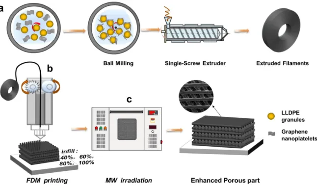
A schematic presentation of the fabrication of the LLDPE/GNPs nanocomposites and the FDM 3D printing process is illustrated in Fig. 1. To prepare the GNPs coated LLDPE composite powders, LLDPE powder was first mixed with various loading of GNPs (1, 2, 4, 6, 8 and 10 wt%) using a ball milling machine (QM-3SP4, Nanjingnanda instrument Co., Ltd, China) at 350 rpm for 1 h. The prepared composite powders were then extruded in a single-screw extruder (RM-200C, Harbin HAPRO Electric Technology Co., Ltd. China) to prepare the corresponding filaments through careful control of the extrusion temperature at 170 ºC, screw rotation speed adjusted at 15 rpm and diameter of the extruded filaments set at 1.75 ± 0.05 mm (by adjusting the drawing speed). Here below, the LLDPE/GNPs filaments with different content of GNPs are named LLDPE/1GNPs, LLDPE/2GNPs, LLDPE/4GNPs, LLDPE/6GNPs, LLDPE/8GNPs and LLDPE/10GNPs, respectively, where the “LLDPE/nGNPs” means that n wt% loading of GNPs were incorporated in LLDPE matrix.
Fig. 1. Schematic diagram for the preparation of LLDPE/GNPs nanocomposite filaments (a), FDM 3D printing process (b) and MW irradiation post-manufacture process (c).
2.3 Fabrication of LLDPE/GNPs nanocomposite parts via FDM 3D printing
All the measured samples were fabricated on a German RepRap×350pro FDM printer. The corresponding 3D model was constructed using Pro/Engineer 5.0, and
then exported as a STL file for printing. The following 3D printing parameterswere adopted: nozzle diameter of 0.4 mm, layer thickness of 300 μm, nozzle temperature of
170 C and printing speed of 150 mm/min. To investigate the influence of different printing structure on the EMI SE of the obtained LLDPE/GNPs nanocomposite parts
0 60 (pattern 2) and -60 0 60 (pattern 3). These filling patterns are illustrated in Fig. S1. The notations 0 × 0, 0 × 60 and -60 × 0 × 60 mean that the printing filaments
were alternately deposited onto the building plate along 0, 0/60 and -60/0/60 directions (relative to a fixed horizontal direction), respectively. In addition, the object infill density used in this study was chosen at 40, 60, 80 and 100%, respectively, as illustrated in Fig. 1b. When the infill density is less than 100%, it is believed that the 3D printed part possesses a porous structure. For convenient discussion, the obtained LLDPE/GNPs nanocomposite parts with different printing pattern and infill density are named LGm-n, where the “LGm-n” means that the samples were made using the
"mth" printing pattern and infill density of “n%”, respectively. For instance, LG 1, LG2
and LG3 samples represent the LLDPE/GNPs nanocomposites parts printed with
pattern 1, 2 and 3, respectively ????, and 100% infill density????; LG1-40 sample
represents the LLDPE/GNPs nanocomposite parts which were obtained by adopting the printing pattern 1 and the infill density of 40%. However, for tensile test, the required dumbbell-shaped samples (with dimension of length 25 mm, width 5 mm (narrow section) and 10 mm (wide section), and thickness 2 mm) were printed
according to three different filling patterns (0 0, 45 45 and 90 90). The corresponding printed samples were named FS0, FS45 and FS90, respectively.These
90 90 mean that the printing filaments are deposited onto the building plate along
0°, 45 and 90° direction (relative to the sample length direction), respectively. To investigate the effect of the MW irradiation on the mechanical property and EMI SE, the corresponding FDM parts were put in a microwave furnace for irradiation
sintering. Considering that a large concentration of GNPs in LLDPE would lead to strong MW absorption and hence a high temperature due to long irradiation time and high irradiation power which could destroy the sample, we specially sintered the LLDPE/GNPs nanocomposite 3D printed parts with different loading of GNPs (0-10.0 wt%) over different irradiation time (10-40 s) under a fixed MW power of 300 W. The irradiation time for the sample with 0.0/2.0, 4.0, 6.0 and 8.0/10.0 wt% loading of GNPs was selected as 40, 30, 20 and 10 s, respectively. The microwave irradiated sample was correspondingly named M-FSx where x represents one of the 3 filling
patterns (0 0, 45 45 and 90 90).
2.4 Characterization
The morphology of the surface and the fractured surface of the filaments and the corresponding 3D printed parts was investigated with a scanning electron microscope (SEM) (FEI Instrument, USA)at an accelerating voltage of 20 kV. The test samples were first fractured in liquid nitrogen and then sputtered with gold particles before observation.
FS45 and FS90) were evaluated using an Instron 5567 instrument (Instron Co., Ltd,
United States) and the crosshead speed was 20 mm min-1. For each sample, there were
five printed specimens with the same filling pattern for tensile test, and the averaged value was calculated as the final result.
The bulk densities (ρ) of the sintered 3D printed parts were obtained from the equation ρ=m/v, where m and v are the weight (g) and volume (cm3) that were
measured with an electronic balance and a vernier caliper.
The rheological measurements of the LLDPE/GNPs nanocomposites were carried out on a parallel-plate rotational rheometer (TA Instruments, USA). The dynamic frequency sweeps were carried out by using a 25 mm diameter parallel plate with a 2 mm sample thickness and a fixed strain of 5% at 170 ºC. The scanning frequency ranged from 0.01 to 100 Hz.
The electrical conductivity measurement was performed with a digital multimeter (Fluke 8062A, USA), and the corresponding electrical conductivity was
calculated according to the equation σ=L/(SR), where σ and R represent the electrical conductivity and electrical resistance, respectively, and L and S represent the distance between two electrodes and the cross-section area of the cylindrical 3D printed sample, respectively. Before measurement, both ends of the cylindrical 3D
printed sample were coated with a conductive silver glue to ensure good contact
between the sample and the electrodes. For each sample, five replicates were
The EMI shielding performance was evaluated by using a coaxial test cell (APC-7 connector) in conjunction with an Agilent N5230 vector network analyzer (USA) in the range of X-band frequency (8.2-12.4 GHz). FDM 3D printed disk samples with 13.0 mm diameter and 2 mm thickness were completely enclosed by the coaxial test cell consisting of two waveguide connectors and the S-parameters (S11 and S21) of
each sample were accordingly recorded [33]. The power coefficients including
reflection (R), absorption coefficient (A) and transmission (T), and the corresponding electromagnetic reflection shielding (SER), absorption shielding (SEA) and total EMI
SE (SET) were calculated from the measured scattering parameters (S11 and
S21)according to the following equations [24, 41].
R=S112=S222, T=S122=S212 (1) SER=10lg
(
1 1 − R)
=10 lg(
1 1 − S11 2)
(2) SEA=10 lg(
1− R T)
=10 lg(
1− S112 S212)
(3) SET=SER+SEA=20lg(
S21)
(4)3. Results and discussion
3.1 Preparation and characterization of LLDPE/GNPs nanocomposite filaments
The GNPs coated LLDPE particles prepared by ball-milling are illustrated in Supporting Information (Fig. S3). From the magnified SEM image of the coated particles, it can be seen that the surface of the dark modified LLDPE particles are very
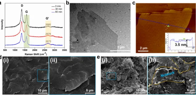
rough. There are many GNPs particles uniformly and tightly attached to the surface of LLDPE particles under the effect of the very strong impact and shear force of the grinding balls generated during ball milling. To investigate the influence of ball milling on the exfoliation of GNPs particles, Raman spectroscopy measurement was applied to characterize the exfoliation of GNPs produced by ball milling. The results are shown in Fig. 2. As can be seen, the intensity of G’-band at approximately 2680 cm-1 increases relative to the small peak nearby with increasing milling time from 0 to
60 min (Fig. 2a). It is simultaneously noted that the ball milling also produces a down shift of the G’-band. The above results suggest that the ball milling process could decrease the thickness of GNPs layers, which is consistent with a previous work reported by other researchers [42]. Furthermore, it is known that the G-band is
associated with the in-plane vibration of the SP2 carbon atom of GNPs [33]. When the
number of GNPs layers decreases, the intensity of the G-band decreases significantly, and meanwhile the intensity of G’-band increases instead [42]. From Fig. 2a, it can be also seen that, after ball milling for 60 min, the intensity IG of G-band obviously
decreases while IG’ (the intensity of G’-band) significantly increases (as mentioned
before). As a result, the IG/IG’ ratioof the milled GNPs is significantly less than that of
the unmilled GNPs. The above results demonstrate an exfoliation of the GNPs particles under ball milling. To further investigate and confirm this observation, TEM and AFM characterizations of the samples were carried out as well. The TEM image o Fig. 2b shows a typical few-layer graphene which was exfoliated by ball milling for 60 min, where the GNPs presents a micro-scale length and a much thinner
thickness. The AFM results of Fig. 2c also show that the GNPs extracted from the coated LLDPE particles after 60 min treatment possess an obviously decreased thickness of 3.5 nm. In combination with the previous Raman analysis data, it can be concluded that the ball-milling technology can really produce an exfoliation of the GNPs.
On the basis of successful GNPs exfoliation by ball milling, the milled mixture of LLDPE and GNPs were extruded to prepare nanocomposite filaments. The digital photos of the obtained filaments of pure LLDPE and nanocomposites (with 6 and 10 wt% GNPs incorporated) are shown in Fig. S4. As can be seen, the appearance of the latter is as smooth as that of the former. The morphology of the fractured filaments surface is illustrated in Figs. 2d-e. It can be seen that pure LLDPE filaments shows a relatively smooth fractured surface (Fig. 2di-ii). After ball milling process, the
LLDPE/10GNPs nanocomposite filaments show well-dispersed GNPs in LLDPE matrix due to the exfoliation of GNPs (Fig. 2ei). It is also found that there is even a
connected network structure formed in 10.0 wt% loading GNPs/LLDPE filaments (Fig. 2eii, magnified image). This is because under the effect of the single-screw
extrusion shear force field, the segregated GNPs network structure in the coated polymer particles could be dynamically stretched to form an interconnected network [43],. This is further illustrated in Fig. S5cii (Supporting Information). The above
results indicate that the ball milling process contributes to the exfoliation of GNPs particles and may lead to the formation of connected network structures.
Fig. 2. Preparation and morphology of LLDPE/GNPs composites filaments. Raman spectra of LLDPE/10GNPs co-powders with different milling time at 532-nm excitation wavelength (a), TEM image of GNPs separated from co-powders (b), AFM image of GNPs deposited on mica using ethanol solution (c) (inset is the corresponding height curve), and SEM images of the fractured surface of as-prepared filaments, pure LLDPE (di-ii) and LLDPE/10GNPs (ei-ii).
3.2 FDM 3D printing of LLDPE/GNPs nanocomposites
To further evaluate the 3D printability of the LLDPE/GNPs nanocomposites, dynamic rheological measurement was used to characterize their rheological behaviors. The apparent viscosity (η) and storage modulus (G′) dependence on frequency (ω) is shown in Figs. 3a-b. It can be seen that the incorporation of the rigid
GNPs particles in LLDPE matrix significantly increases both (Fig. 3a) and G′ (Fig. 3b). This increase can be attributed to enhanced interfacial interactions between GNPs and LLDPE molecular chains due to the high surface area of the exfoliated GNPs and the formation of GNPs networks in polymer matrix [44, 45]. In addition,
the pronounced G′ plateau of the nanocomposites with 6-10 wt% loading of GNPs occurs at low frequency and this adequately indicates the formation of a well-interconnected filler networks structure in nanocomposites [46, 47]. Furthermore, it is
also found that the apparent viscosities (η) of all samples almost linearly decrease
with increasing frequency, suggesting that the LLDPE/GNPs nanocomposites have an
obvious shear thinning behavior. This property could ensure that the melt of filament
can smoothly pass through the nozzle and the corresponding parts could be
successfully printed. Figs. 3c-e show the digital photo of a printed cylindrical part of
LLDPE/10GNPs together with SEM images of its porous microstructure. It can be clearly seen that the printed part exhibits a perfect profile (Fig. 3c), and the deposited filaments are aligned very regularly and also present a very smooth surface. Each printed layer of the parts has the same thickness. More importantly, triangle porous structures consisting of multilayer filaments are formed through the FDM 3D printing. It is worth noting that such the porous structures inside the printed parts could effectively enhance the interfacial areas, which are advantageous for the attenuation of the electromagnetic waves, thus enhancing the EMI shielding property (this will be discussed below). Additionally, the super-depth-of-field images of 3D printed parts (Fig. 3f) clearly show the layer thickness of the printing filaments could be as small as the designated 300 μm, indicating that the FDM printing of LLDPE nanocomposites can achieve a high level of accuracy.
Fig. 3. Printability exploration of LLDPE/GNPs nanocomposites. Dynamic rheological properties: complex viscosity η (a) and storage modulus G′ (b) of pure LLDPE and LLDPE/GNPs nanocomposites with different GNPs loading versus angular frequency at 170 °C; FDM 3D-printed porous part of LLDPE/10GNPs with 40% infill density: digital photo (c), SEM image of the internal microstructure in low magnification (d) and high magnification (e); super-depth-of-field image of the corresponding FDM 3D-printed part along thickness direction (f).
3.3 Mechanical properties of FDM 3D printed LLDPE/GNPs parts
Stress-strain curves of LLDPE/10GNPs parts for different printing pattern (FS0, FS45 and FS90) (a); mechanical property comparison between FS90 and M-FS90 parts: tensile strength (b) and elongation at break (c); SEM images of the stretched fractured surfaces of LLDPE/6GNPs (d) and LLDPE/10GNPs (e) parts before (d-i and e-i) and after (d-ii and e-ii) MW irradiation.
The tensile properties of the FDM 3D printed LLDPE/GNPs nanocomposites
with different loading of GNPs and filling pattern (0 0, 45 45 and 90 90) are compared in Fig. 4. Fig. 4a compares the stress-strain curves of LLDPE/10GNPs parts for different filling patterns. It is clearly seen that the parts FS0 show the highest
ultimate tensile strength of 10.5 MPa and elongation at break of 20.26%, which are nearly 1.5 and 3 times as much as that of FS90 (with 7.14 MPa in strength and 6.13%
in strain), respectively. This is because in FS90 pattern, the bonding interfaces between
filaments in the same deposition layer is perpendicular to the stress direction, thus making the bonding interfaces be the weakness of the whole structure. The tensile property of FS90 sample is therefore much lower, as also reported in the previous
publications [37, 48]. For this reason, the 90 90 printing pattern was selected to characterize and evaluate the interfacial bonding strength of FDM 3D printed parts here. In order to enhance the interfacial strength, MW irradiation was applied to treat the LLDPE/GNPs nanocomposite parts so as to increase their interlaminar bonding strength. The mechanical property results of FS90 and M-FS90 samples with various
loading, the tensile strength first increases and then decreases, while the elongation at break continuously decreases. More importantly, it is found that MW treatment equivalently enhances the tensile strength and the elongation at break of all the 3D printed parts. For tensile strength, the higher GNPs loading produces to the greater enhancement , but for elongation at break, the optimum increase degree occurs in the range of 4-6 wt%. For instance, M-LLDPE/10GNPs shows a remarkably enhanced tensile strength of 15.5 MPa, which is more than twice as high as that of untreated LLDPE/10GNPs at 7.14 MPa. However, pure LLDPE and LLDPE/2GNPs after microwave irradiation show only slight increase. Similarly, the elongation at break of M-LLDPE/6GNPs reaches the optimum value of ~20%, which is about two times as high as that of LLDPE/6GNPs at 10%. The above results show that post-manufacture microwave irradiation could effectively enhance the interfacial bonding strength of LLDPE/GNPs 3D printed parts, especially in the GNPs loading range of 4-10 wt%. The above enhancement can be explained by the selective absorption of microwaves by the GNPs fillers. Obviously, the higher loading of homogeneously dispersed GNPsin LLDPE matrix facilitate more MW absorption and thereby heating of parts. This effect can significantly improve the interfacial bonding and hence produces a dramatic enhancement in interfacial strength, and therefore tensile property. However, for the parts with low GNPs loading (0-2 wt%), there is much less microwave absorption. Consequently, the improvement in mechanical performance is very limited. The above analyzes have been verified by a morphological characterization of LLDPE/GNPs 3D printed parts (LLDPE/6GNPs and LLDPE/10GNPs) before and
after microwave treatment (Figs. 4d-e). It is very clear that the interfacial bonding of the 3D printed parts is substantially enhanced after microwave irradiation, particularly for LLDPE/10GNPs sample (Fig. 4d-i versus ii and Fig. 4e-i versus ii).
3.4 EMI shielding performances of FDM 3D printed LLDPE/GNPs parts
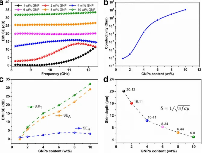
Fig. 5. EMI shielding performance of the FDM 3D printed parts (2.2 mm thickness, LG3, filling pattern of -60 0 60, ????100 % infill density???) treated with microwave irradiation: EMI SET of the printed parts with different GNPs loading (a), average dc electrical conductivity of the printed parts as a function of GNPs loading (b), EMI SET, SEA and SER of the printed parts with different GNPs loading at the frequency of 10 GHz (c) and skin depth of the printed parts with different GNPs loading at the frequency of 10 GHz (d).
EMI shielding measurements of the LLDPE/GNPs nanocomposites parts were performed in the X-band (8.2-12.4 GHz), which is the frequency range widely used in telecommunication applications. To investigate the effect of MW post-manufacture treatment on the total EMI SE of the LLDPE/GNPs printed parts, the EMI SET of the
printed parts with different GNP loading before and after MW irradiation was evaluated and the results are shown in Fig. S6 (Supplementary Information). As can be seen, the MW treatment has little impact on EMI SE at various GNPs loadings. However, given the fact that the microwave treatment significantly enhances the mechanical performances of LLDPE/GNPs printed parts with higher loading of GNPs, all the following discussion is based on the MW irradiated parts. Fig. 5a compares the EMI SE of the LLDPE/GNPs printed parts with various GNPs loading (EMI SE of pure LLDPE is not represented here because pure LLDPE is almost transparent to electromagnetic waves in the X band). It can be seen that the EMI SE of the printed part dependents only slightly on frequency in the X-band range, especially at higher GNPs loading. This indicates the absence of resonant effect between the wavelength and the substructure of the sample. The higher the GNPs loading, the larger the EMI SE. Generally, with increasing GNPs loading, the EMI SE of the printed parts increases significantly. It is also seen that only 6.0 wt% GNPs loading can impart the printed parts the EMI SE value of about 20.3 dB, which already achieves the minimum level (20 dB) required for the general commercial applications [23] Furthermore, it is worth noting that by increasing GNPs loading to
mm thickness. This remarkably-small EM transmission is due to the existence of GNPsconductive network in the LLDPE matrix, which was verified by SEM analysis of the morphology (Fig. 2e) and rheological characterization (Fig. 3b). As we know, the EMI SE of the printed parts depends on the electrical conductivity of the nanocomposite . The results of electrical conductivity are displayed in Fig. 5b. It can be seen that with the increase of GNPs loading from 1 wt% to 10 wt%, the corresponding static electrical conductivity shows a remarkable increase (S-curve)
from 8.7610-6 to 12 S/m. The significant increase of electrical conductivity with
GNPs loading results from the construction of 3D conductive networks and thus contributes to the substantial improvement of EMI SE.
To investigate the EMI shielding mechanisms of LLDPE/GNPs nanocomposite parts, the total shielding (SET), absorption (SEA) and reflection (SER) of the printed
parts with different GNPs loading at the frequency of 10 GHz are collected in Fig. 5c for further analysis. As can be seen for SER and SEA, which both contribute to SET,,
with increasing GNPs loading, SEA increases remarkably whereas SER just increases
slightly. For instance, the SET, SEA and SER of LLDPE/10GNPs part reach ∼32.4,
∼29.2 and ∼3.2 dB at 10 GHz, respectively. Obviously, the contribution of SEA to
SET is much larger than that of SER, indicating an absorption-dominant EMI shielding
mechanism (electrical loss mechanism) of the LLDPE/GNPs nanocomposite 3D printed parts [24, 49]. The involved SET can be defined as the logarithmic ratio of the
SET(dB)=10lg ( P i/P t ) (5)
where Pi is the incident power and Pt is the transmitted power in decibel (dB). Generally, the blocking of 99% incident electromagnetic power can make the materials meets the requirement for practical application (20 dB) in EMI shielding
devices [21]. The results indicate that only 0.93% to 0.058% of EM irradiation is
transmitted through the printed porous shielding parts with 6-10 wt% of GNPs
loading, i.e. 99.07% to 99.942% of electromagnetic power is blocked, showing the
excellent EMI shielding properties of our LLDPE/GNPs printed parts.
The skin depth, δ, is an important parameter for evaluating the shielding capability of a material. Skin depth usually determines the SEA values of materials
with a fixed thickness d [50]. According to the classical electromagnetic theory, for
the CPCs, the absorption effectiveness SEA can be expressed by Eq. (6) [51].
SEA(dB)=20dδlg e (6)
which is valid when d >> δ. The skin depth depends on the frequency f according to Eq. (7) [52]
δ= 1
√
πfuσ (7)where σ is the electrical conductivity and µ is the magnetic permeability of the material ( µr = µ0 for the nonmagnetic LLDPE/GNPs parts).Fig. 5d shows the
calculated skin depth of the LLDPE/GNPs printed part with various GNPs loading at the frequency of 10 GHz. A sharp decrease in skin depth is clearly observed with increasing GNPs loading, as the result of an increase of ac conductivity.For instance,
the skin depth of the printed parts with 4 wt% and 10.0 wt% GNPs loading is 10.4 and 5.0 µm, respectively, which is much smaller than that of the thickness of the tested sample (2.2 mm). This also reveals that the LLDPE/GNPs parts printed in this study possess the excellent EMI shielding properties.
Fig. 6 Effect of the printed porous structure on EMI SE properties of LLDPE/10GNPs parts: digital photos of LG1-60 (a-i), LG2-60 (a-ii) and LG3-60 (a-iii) FDM printed parts, SEM images of the corresponding fractured surfaces of LG1-60 (b-i), LG2-60 (b-ii) and LG3-60 (b-iii), EMI SET of the LLDPE/GNPs parts with different filling pattern (1-3) and different infill density (60% and 100%) (c), EMI SET, SEA and SER dependence of filling pattern and infill density at the frequency of 10 GHz (d), effect of infill density on EMI SET of the LLDPE/GNPs parts (e), and effect of infill density on the SSE/t of the LLDPE/GNPs parts in X-band frequency (f).
To evaluate the effect of filling pattern on the total EMI SE of the LLDPE/GNPs
-60060). The digital photos of the corresponding 3 printed parts (i-iii) are shown in Fig. 6a. Accordingly, the filament alignments of the above mentioned 3 printed parts
are clearly presented by SEM and super-depth-of-field images (Fig. S7, Supporting
Information). Fig. 6b shows the low-magnification SEM morphology of the fractured
surface of LG1-60 (00), LG2-60 (060) and LG3-60 (-60060) parts. The deposition
structures of the filaments can be clearly observed from the cross-section SEM
images. After MW treatment, the filaments are relatively more closely bonded,
resulting in excellent interfacial strength. Fig. 6c shows the total EMI SE of the
LLDPE/10GNPs printed parts with the mentioned three filling patterns at 60% and
100% infill density, respectively. As can be seen, when the infill density is 100%, the
EMI SE of all samples is approximately in the range of 30~32 dB and the filling
pattern shows small effect on EMI SE (LG3-100 is the optimum). However, when the
infill density decreases to 60%, the difference between different filling patterns is very
significant, e.g., at 10 GHz, the LG3-60 part possesses the optimum EMI SE of 32.4
dB, and however LG1-60 part has the lowest one (23.8 dB). Overall, the EMI SE of
infill density of 100% is higher than that of 60%, and the difference among different
patterns following the order: filling pattern LG3>LG2>LG1. For in-depth
understanding of such difference, the SET, SEA, and SER of the LLDPE/10GNPs parts
obtained with different filling pattern and infill density at the frequency of 10 GHz are further compared in Fig. 6d. As can be seen, both SER and SEA basically contribute to
from SEA, i.e. absorption. Obviously, SEA of LG3 series is the largest. For this reason,
LG3 series are selected to be further explored. The influence of infill density on the
total EMI SE (SET) of LG3 printed parts (LLDPE/10GNPs) in the X-band frequency
range is demonstrated in Fig. 6e. As can be seen, overall, the averaged EMI SE of
various sample decreases from 32.5 to 29 dB as following: LG3-100>LG3-80>LG
3-60>LG3-40, i.e., the highest infill density leads to the highest SE. However, it should be
noted that the EMI SE values for infill density in the range of 60-100% are actually
close and that of 40% is lower to some extent. Because high infill density means
high weight, the fabrication of the heaviestparts withsimilar EMI SE is not
cost-effective. In other words, the density and performances of the 3D-printed parts
should be comprehensively considered. The 3D printed parts with low infill density
and lightweight porous structure seems to be more favorable. For this purpose, a
thickness normalized specific SE value of SSE/t (SE divided by the sample density
and thickness) [23] was used to further evaluate the EMI SE performance of
LLDPE/10GNPs parts (Fig. 6f). Obviously, there is a significant difference between
different infill densities. The printed part with lower infill density clearly shows a
much higher SSE/t. For instance, by decreasing the infill density from 100% to 40%,
the average SSE/t of printed parts increases remarkably from 152 to 318 dB cm2 g−1.
As a result, the lightweight porous LLDPE/10GNPs parts printed with filling pattern 3
and infill density of 40% actually possesses the optimum SSE/t while having a
transmission shielding effectiveness around 30 dB.
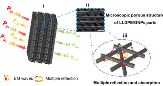
shielding mechanism is proposed in Fig. 7. When the incident EM waves are applied
to the LLDPE/GNPs part surface, a small fraction of the electromagnetic waves are
reflected back. The remaining electromagnetic waves are transmitted inside and
further interact with the porous structures of the printed parts, leading to energy loss
of the electromagnetic waves. At the same time, the printed porous layered structure
of the LLDPE/GNPs parts enhance the interfacial areas and hence facilitate multiple
internal reflections of electromagnetic waves, resulting in more absorption and energy
dissipation [36, 53], as shown in the enlarged picture (Fig. 7-iii). Of course, this
simple explanation needs further confirmation by computer simulation of the EM
wave propagation inside the structure. Herein, it should be stressed again that the
lower infill density can simultaneously achieve an enhancement in the specific EMI
SE and reduction in density (lightweight of part). The LLDPE/GNPs 3D printed part
with infill density of 40% possesses an attracting low density (only 0.42 g/cm3) and
the highest SSE/t value, showing a very promising application prospect. The various
types of complex porous parts can be printed under the similar conditions, which are
represented in Fig. S8 (Supporting Information). Obviously, this is a facile strategy
which could be highly proposed to fabricate the lightweight and multifunctional parts
Fig. 7 Schematic diagram for illustrating the EMI shielding mechanism of LLDPE/GNPs printed part.
Conclusions
In conclusion, lamellar porous and lightweight LLDPE/GNPs nanocomposite structures with enhanced interfacial bonding strength and the excellent EMI SE were successfully prepared through a combination of FDM 3D printing, ball milling and microwave irradiation strategies. The LLDPE/GNPs printed parts show a remarkable EMI SE of 32.4 dB at 10 GHz. The ball milling technology was used to realize exfoliation of GNPs and prepare GNPs encapsulated LLDPE particles, which is advantageous for the dispersion of GNPs in the polymer matrix, the construction of a segregated conductive network and microwave absorption. The FDM 3D printing strategy could enable us to tailor the EMI SE of the LLDPE/GNPs printed parts by adjusting the printing parameters, and realize the fabrication of lightweight and layered porous 3D printed parts with complex shape/structure. The results obtained in the present work show that the specific EMI SE (SSE/t) of the LLDPE/GNPs printed parts is dramatically improved with decreasing the infill density from 100% to 40%.
In addition, microwave irradiation technology significantly enhances the interfacial bonding between filaments of the 3D printed parts with higher GNPs loading (4-10 wt %), thus resulting in a remarkable increase in both tensile strength and elongation at break. Under the optimized preparation conditions, the fabricated LLDPE/GNPs 3D printed porous parts possess excellent EMI shielding effectiveness with SSE/t equalto 318 cm2g−1, significantly enhanced mechanical robustness with 13.63 MPa tensile
strength and lightweight feature (density of only 0.42 g/cm3). By an innovative
combination of the above approaches, high-performance EMI shielding parts with various complex geometry and structure can be fabricated. The current study provides a promising facile strategy for fabricating high-performance EMI shielding 3D printed parts to be potentially applied in aerospace facilities and lightweight portable electronic devices. Still higher EMI shielding performance of 3D printed parts can be expected by optimizing more complex 3D printing structures, and applying different filling patterns along their thickness direction.
Acknowledgments
This work is financially supported by the National Key R&D Program of China (2017YFE0111500), the National Natural Science Foundation of China (51933007 and 51721091), the European Union’s H2020-MSCA-RISE-734164 Graphene 3D Project, the Project of State Key Laboratory of Polymer Materials Engineering (Sichuan University) (sklpme2020-2-01), the Program of Innovative Research Team for Young Scientists of Sichuan Province (2016TD0010), and the Fundamental Research Funds for the Central Universities.
References
[1] W.T. Cao, F.F. Chen, Y.J. Zhu, Y.G. Zhang, Y.Y. Jiang, M.G. Ma, F. Chen, Binary Strengthening and Toughening of MXene/Cellulose Nanofiber Composite Paper with Nacre-Inspired Structure and Superior Electromagnetic Interference Shielding Properties, ACS nano 12(5) (2018) 4583-4593.
[2] W.-C. Yu, G.-Q. Zhang, Y.-H. Liu, L. Xu, D.-X. Yan, H.-D. Huang, H. Tang, J.-Z. Xu, J.-Z.-M. Li, Selective electromagnetic interference shielding performance and superior mechanical strength of conductive polymer composites with oriented segregated conductive networks, Chemical Engineering Journal 373 (2019) 556-564. [3] C.-F. Cao, G.-D. Zhang, L. Zhao, L.-X. Gong, J.-F. Gao, J.-X. Jiang, L.-C. Tang, Y.-W. Mai, Design of mechanically stable, electrically conductive and highly hydrophobic three-dimensional graphene nanoribbon composites by modulating the interconnected network on polymer foam skeleton, Composites Science and Technology 171 (2019) 162-170.
[4] F. Kargar, Z. Barani, M. Balinskiy, A.S. Magana, J.S. Lewis, A.A. Balandin, Dual-Functional Graphene Composites for Electromagnetic Shielding and Thermal Management, Advanced Electronic Materials 5(1) (2019) 1800558.
[5] S.T. Hsiao, C.C. Ma, W.H. Liao, Y.S. Wang, S.M. Li, Y.C. Huang, R.B. Yang, W.F. Liang, Lightweight and flexible reduced graphene oxide/water-borne polyurethane composites with high electrical conductivity and excellent electromagnetic interference shielding performance, ACS applied materials & interfaces 6(13) (2014) 10667-78.
[6] M.-S. Cao, W.-L. Song, Z.-L. Hou, B. Wen, J. Yuan, The effects of temperature and frequency on the dielectric properties, electromagnetic interference shielding and microwave-absorption of short carbon fiber/silica composites, Carbon 48(3) (2010) 788-796.
[7] Y. Wang, Y. Du, R. Qiang, C. Tian, P. Xu, X. Han, Interfacially Engineered Sandwich-Like rGO/Carbon Microspheres/rGO Composite as an Efficient and Durable Microwave Absorber, Advanced Materials Interfaces 3(7) (2016) 1500684.
[8] X. Zhang, J. Zhang, L. Xia, J. Wang, C. Li, F. Xu, X. Zhang, H. Wu, S. Guo, Achieving high-efficiency and robust 3D thermally conductive while electrically insulating hybrid filler network with high orientation and ordered distribution, Chemical Engineering Journal 334 (2018) 247-256.
[9] W. Wang, R. Li, M. Tian, L. Liu, H. Zou, X. Zhao, L. Zhang, Surface silverized meta-aramid fibers prepared by bio-inspired poly(dopamine) functionalization, ACS applied materials & interfaces 5(6) (2013) 2062-9.
[10] Y. Wang, L.-j. Ni, F. Yang, F.-q. Gu, K. Liang, K. Marcus, Y.-d. Wan, J.-j. Chen, Z.-s. Feng, Facile preparation of a high-quality copper layer on epoxy resin via electroless plating for applications in electromagnetic interference shielding, Journal of Materials Chemistry C 5(48) (2017) 12769-12776.
[11] K. Zhang, Y. Li, H. Zhou, M. Nie, Q. Wang, Z. Hua, Polyurethane/carbon fiber composite tubular electrode featuring three-dimensional interpenetrating conductive network, Carbon 139 (2018) 999-1009.
[12] J. Ling, W. Zhai, W. Feng, B. Shen, J. Zhang, W. Zheng, Facile preparation of lightweight microcellular polyetherimide/graphene composite foams for electromagnetic interference shielding, ACS applied materials & interfaces 5(7) (2013) 2677-84.
[13] L.-C. Jia, G. Zhang, L. Xu, W.-J. Sun, G.-J. Zhong, J. Lei, D.-X. Yan, Z.-M. Li, Robustly Superhydrophobic Conductive Textile for Efficient Electromagnetic Interference Shielding, ACS applied materials & interfaces 11(1) (2018) 1680-1688. [14] Y.J. Wan, P.L. Zhu, S.H. Yu, R. Sun, C.P. Wong, W.H. Liao, Anticorrosive, Ultralight, and Flexible Carbon-Wrapped Metallic Nanowire Hybrid Sponges for Highly Efficient Electromagnetic Interference Shielding, Small 14(27) (2018) e1800534.
[15] C. Li, C. Zhou, J. Lv, B. Liang, R. Li, Y. Liu, J. Hu, K. Zeng, G. Yang, Bio-molecule adenine building block effectively enhances electromagnetic interference shielding performance of polyimide-derived carbon foam, Carbon 149 (2019) 190-202.
[16] M. Kim, J.H. Jeong, J.Y. Lee, A. Capasso, F. Bonaccorso, S.H. Kang, Y.K. Lee, G.H. Lee, Electrically Conducting and Mechanically Strong Graphene-Polylactic Acid Composites for 3D Printing, ACS applied materials & interfaces 11(12) (2019) 11841-11848.
[17] A. Ameli, M. Nofar, S. Wang, C.B. Park, Lightweight polypropylene/stainless-steel fiber composite foams with low percolation for efficient electromagnetic interference shielding, ACS applied materials & interfaces 6(14) (2014) 11091-100. [18] Y. Tang, S. Gong, Y. Chen, L.W. Yap, W. Cheng, Manufacturable Conducting Rubber Ambers and Stretchable Conductors from Copper Nanowire Aerogel Monoliths, ACS nano 8(6) (2014) 5707-5714.
[19] S. Deville, E. Saiz, R.K. Nalla, A.P. Tomsia, Freezing as a Path to Build Complex Composites, Science 311 (2006) 515-518.
[20] D.-X. Yan, P.-G. Ren, H. Pang, Q. Fu, M.-B. Yang, Z.-M. Li, Efficient electromagnetic interference shielding of lightweight graphene/polystyrene composite, Journal of Materials Chemistry 22(36) (2012) 18772.
[21] D. Feng, Q. Wang, D. Xu, P. Liu, Microwave assisted sinter molding of polyetherimide/carbon nanotubes composites with segregated structure for high-performance EMI shielding applications, Composites Science and Technology 182 (2019) 107753.
[22] D. Feng, D. Xu, Q. Wang, P. Liu, Highly stretchable electromagnetic interference (EMI) shielding segregated polyurethane/carbon nanotube composites fabricated by microwave selective sintering, Journal of Materials Chemistry C 7(26) (2019) 7938-7946.
[23] D. Feng, P. Liu, Q. Wang, Exploiting the piezoresistivity and EMI shielding of polyetherimide/carbon nanotube foams by tailoring their porous morphology and segregated CNT networks, Composites Part A: Applied Science and Manufacturing 124 (2019) 105463.
[24] C. Liang, H. Qiu, Y. Han, H. Gu, P. Song, L. Wang, J. Kong, D. Cao, J. Gu, Superior electromagnetic interference shielding 3D graphene nanoplatelets/reduced
graphene oxide foam/epoxy nanocomposites with high thermal conductivity, Journal of Materials Chemistry C 7(9) (2019) 2725-2733.
[25] H.B. Zhang, Q. Yan, W.G. Zheng, Z. He, Z.Z. Yu, Tough graphene-polymer microcellular foams for electromagnetic interference shielding, ACS applied materials & interfaces 3(3) (2011) 918-24.
[26] S. Waheed, J.M. Cabot, P. Smejkal, S. Farajikhah, S. Sayyar, P.C. Innis, S. Beirne, G. Barnsley, T.W. Lewis, M.C. Breadmore, B. Paull, Three-Dimensional Printing of Abrasive, Hard, and Thermally Conductive Synthetic Microdiamond-Polymer Composite Using Low-Cost Fused Deposition Modeling Printer, ACS applied materials & interfaces 11(4) (2019) 4353-4363.
[27] Q. Chen, J.D. Mangadlao, J. Wallat, A. De Leon, J.K. Pokorski, R.C. Advincula, 3D Printing Biocompatible Polyurethane/Poly(lactic acid)/Graphene Oxide Nanocomposites: Anisotropic Properties, ACS applied materials & interfaces 9(4) (2017) 4015-4023.
[28] K. Chizari, M. Arjmand, Z. Liu, U. Sundararaj, D. Therriault, Three-dimensional printing of highly conductive polymer nanocomposites for EMI shielding applications, Materials Today Communications 11 (2017) 112-118.
[29] G. Chen, N. Chen, Q. Wang, Fabrication and properties of poly(vinyl alcohol)/β-tricalcium phosphate composite scaffolds via fused deposition modeling for bone tissue engineering, Composites Science and Technology 172 (2019) 17-28.
[30] S.E. Lowe, G. Shi, Y. Zhang, J. Qin, S. Wang, A. Uijtendaal, J. Sun, L. Jiang, S. Jiang, D. Qi, M. Al-Mamun, P. Liu, Y.L. Zhong, H. Zhao, Scalable Production of Graphene Oxide Using a 3D-Printed Packed-Bed Electrochemical Reactor with a Boron-Doped Diamond Electrode, ACS Applied Nano Materials 2(2) (2019) 867-878. [31] J.H. Kim, W.S. Chang, D. Kim, J.R. Yang, J.T. Han, G.W. Lee, J.T. Kim, S.K. Seol, 3D printing of reduced graphene oxide nanowires, Advanced materials 27(1) (2015) 157-61.
[32] S. Gantenbein, K. Masania, W. Woigk, J.P.W. Sesseg, T.A. Tervoort, A.R. Studart, Three-dimensional printing of hierarchical liquid-crystal-polymer structures,
Nature 561(7722) (2018) 226-230.
[33] L. Yang, Y. Chen, M. Wang, S. Shi, J. Jing, Fused Deposition Modeling 3D Printing of Novel Poly(vinyl alcohol)/Graphene Nanocomposite with Enhanced Mechanical and Electromagnetic Interference Shielding Properties, Industrial & Engineering Chemistry Research 59(16) (2020) 8066-8077.
[34] L. Ecco, S. Dul, D. Schmitz, G. Barra, B. Soares, L. Fambri, A. Pegoretti, Rapid Prototyping of Efficient Electromagnetic Interference Shielding Polymer Composites via Fused Deposition Modeling, Applied Sciences 9(1) (2018) 37.
[35] D.P. Schmitz, L.G. Ecco, S. Dul, E.C.L. Pereira, B.G. Soares, G.M.O. Barra, A. Pegoretti, Electromagnetic interference shielding effectiveness of ABS carbon-based composites manufactured via fused deposition modelling, Materials Today Communications 15 (2018) 70-80.
[36] X. Li, X. Yin, H. Xu, M. Han, M. Li, S. Liang, L. Cheng, L. Zhang, Ultralight MXene-Coated, Interconnected SiCnws Three-Dimensional Lamellar Foams for Efficient Microwave Absorption in the X-Band, ACS applied materials & interfaces 10(40) (2018) 34524-34533.
[37] J. Wang, H. Xie, Z. Weng, T. Senthil, L. Wu, A novel approach to improve mechanical properties of parts fabricated by fused deposition modeling, Materials & Design 105 (2016) 152-159.
[38] L. Yang, S. Li, X. Zhou, J. Liu, Y. Li, M. Yang, Q. Yuan, W. Zhang, Effects of carbon nanotube on the thermal, mechanical, and electrical properties of PLA/CNT printed parts in the FDM process, Synthetic Metals 253 (2019) 122-130.
[39] S. Tarafder, V.K. Balla, N.M. Davies, A. Bandyopadhyay, S. Bose, Microwave-sintered 3D printed tricalcium phosphate scaffolds for bone tissue engineering, Journal of Tissue Engineering and Regenerative Medicine 7(8) (2013) 631-641.
[40] T.J. Imholt, C.A. Dyke, B. Hasslacher, J.M. Perez, D.W. Price, J.A. Roberts, J.B. Scott, A. Wadhawan, Z.Y.M. Tour, Nanotubes in Microwave Fields: Light Emission, Intense Heat, Outgassing, and Reconstruction, Chem. Mater. 15 (2003) 3969-3970. [41] D.-X. Yan, H. Pang, B. Li, R. Vajtai, L. Xu, P.-G. Ren, J.-H. Wang, Z.-M. Li, Structured Reduced Graphene Oxide/Polymer Composites for Ultra-Efficient
Electromagnetic Interference Shielding, Advanced Functional Materials 25(4) (2015) 559-566.
[42] J.B. Wu, M.L. Lin, X. Cong, H.N. Liu, P.H. Tan, Raman spectroscopy of graphene-based materials and its applications in related devices, Chemical Society reviews 47(5) (2018) 1822-1873.
[43] J. Jing, Y. Chen, S. Shi, L. Yang, P. Lambin, Facile and scalable fabrication of highly thermal conductive polyethylene/graphene nanocomposites by combining solid-state shear milling and FDM 3D-printing aligning methods, Chemical Engineering Journal 402 (2020) 126218.
[44] S. Yang, S. Bai, W. Duan, Q. Wang, Production of Value-Added Composites from Aluminum–Plastic Package Waste via Solid-State Shear Milling Process, ACS Sustainable Chemistry & Engineering 6(3) (2018) 4282-4293.
[45] B. Li, W.-H. Zhong, Review on polymer/graphite nanoplatelet nanocomposites, Journal of Materials Science 46(17) (2011) 5595-5614.
[46] S. Shi, Z. Peng, J. Jing, L. Yang, Y. Chen, 3D Printing of Delicately Controllable Cellular Nanocomposites Based on Polylactic Acid Incorporating Graphene/Carbon Nanotube Hybrids for Efficient Electromagnetic Interference Shielding, ACS Sustainable Chemistry & Engineering 8(21) (2020) 7962-7972.
[47] F. Du, R.C. Scogna, W. Zhou, S. Brand, J.E. Fischer, K.I. Winey, Nanotube Networks in Polymer Nanocomposites: Rheology and Electrical Conductivity, Macromolecules 37 9048-9055.
[48] K.I. Byberg, A.W. Gebisa, H.G. Lemu, Mechanical properties of ULTEM 9085 material processed by fused deposition modeling, Polymer Testing 72 (2018) 335-347.
[49] Caichao Wan, Yue Jiao, Xianjun Li, Wenyan Tian, Jian Li, Y. Wu, Multi-dimensional and Level-by-Level Assembly Strategy on Flexible and Sandwich-type Nanoheterostructures for Highperformance Electromagnetic Interference Shielding, Nanoscale (2020).
[50] F. Sharif, M. Arjmand, A.A. Moud, U. Sundararaj, E.P.L. Roberts, Segregated Hybrid Poly(methyl methacrylate)/Graphene/Magnetite Nanocomposites for
Electromagnetic Interference Shielding, ACS applied materials & interfaces 9(16) (2017) 14171-14179.
[51] S. Yang, W. Li, S. Bai, Q. Wang, High-performance thermal and electrical conductive composites from multilayer plastic packaging waste and expanded graphite, Journal of Materials Chemistry C 6(41) (2018) 11209-11218.
[52] Y. Zhan, M. Oliviero, J. Wang, A. Sorrentino, G.G. Buonocore, L. Sorrentino, M. Lavorgna, H. Xia, S. Iannace, Enhancing the EMI shielding of natural rubber-based supercritical CO2 foams by exploiting their porous morphology and CNT segregated networks, Nanoscale 11(3) (2019) 1011-1020.
[53] H. Xu, X. Yin, X. Li, M. Li, S. Liang, L. Zhang, L. Cheng, Lightweight Ti2CT x MXene/Poly(vinyl alcohol) Composite Foams for Electromagnetic Wave Shielding with Absorption-Dominated Feature, ACS applied materials & interfaces 11(10) (2019) 10198-10207.