A Constant-Mass Fuel Delivery System for Use in
Underwater Autonomous Vehicles
by
Theresa Ann Saxton-Fox
Submitted to the Department of Mechanical Engineering
in partial fulfillment of the requirements for the degree of
Bachelor of Science in Mechanical Engineering
at the
MASSACHUSETTS INSTITUTE OF TECHNOLOGY
June 2012
@2012
Theresa Ann Saxton-Fox. All rights reserved.
ARCHNES
The author hereby grants to MIT permission to reproduce and to distribute publicly
paper and electronic copies of this thesis document in whole or in part in any
medium now known or hereafter created.
A u th o r ...
. ...
Department of Mechanical Engineering
May 22, 2012
/
C ertified by
...
A ccepted by ...
Samuel C.
~-Doug Hart
Professor of Mechanical Engineering
Thesis Supervisor
. ..
...
... ...
John H. Lienhard V
Collins Profess
echanical Engineering
Associate Department Head, Education
A Constant-Mass Fuel Delivery System for Use in Underwater
Autonomous Vehicles
by
Theresa Ann Saxton-Fox
Submitted to the Department of Mechanical Engineering on May 22, 2012, in partial fulfillment of the
requirements for the degree of
Bachelor of Science in Mechanical Engineering
Abstract
This thesis describes the design and assembly of two constant-mass fuel tanks to be used in autonomous underwater vehicles (AUVs). The fuel tanks are part of a power supply designed to increase AUV endurance without limiting maneuverability. The fuel tanks allow AUVs to burn liquid fuel while maintaining constant buoyancy, increasing vehicle endurance by a factor of four without sacrificing mission capabilities. The fuel tanks take air and water as ballast in proper proportions to replace the consumed mass of fuel. Active solenoid valves, a fuel pump, and a water pump control the mass flow through the system. The thesis covers the design of the mass flow in the system, the computer modeling of that system, and the prototyping of two constant-mass fuel tanks.
Thesis Supervisor: Doug Hart
Acknowledgments
I would like to thank Ari Frankel, Nate Shoemaker-Trejo, Latifa Hamzah, Jean Sack, and
Jonathan Sue-Ho for being members of the Fuel Team in 2.013, Engineering Systems Design, and 2.014, Engineering Systems Development in 2011 and 2012. They helped conceive of and create the constant-mass fuel tanks discussed in this thesis. I would also like to thank Erich Brandeau, Dan Dorsch, Luke Mooney, and all the members of 2.013 and 2.014 for providing guidance and feedback on the design of the fuel tanks. I would like to acknowledge the incredible support and guidance provided by Doug Hart as the professor in 2.013 and 2.014, as my thesis supervisor, and as a mentor and friend. And finally, I would like to thank Lincoln Laboratory for the financial support that made these tanks possible.
Contents
1 Introduction 13
1.1 Autonomous Underwater Vehicles . . . . 13
1.2 Motivation for Liquid Fuel . . . . 15
1.3 Thesis summary . . . . 16
2 Design 19 2.1 System Requirements . . . . 19
2.2 Theoretical Design . . . . 19
2.2.1 Fuel Delivery System . . . . 20
2.2.2 Buoyancy System . . . . 22
2.3 Head Loss in Piping . . . . 26
2.4 SolidWorks Design . . . . 27
3 Construction and Assembly 31 3.1 Required Parts . . . . 31
3.2 First Prototypes . . . . 33
3.3 Completed Fuel Tanks . . . . 33
4 Testing 39 4.1 Leak Detection . . . . 39
4.2 Fuel Pump Characterization. . . . . 39
4.3 Water Pump Calibration. . . . . 41
A.1 Fuel Flow Sensor Specifications . . . . 47
List of Figures
1-1 Hydroid REMUS 600... . 15
1-2 Early renewable recharging concept . . . . 15
1-3 Full system prototype . . . . 17
2-1 Containment tank . . . . 20
2-2 Flowmeter . . . . 21
2-3 Mass flow of gasoline to engine . . . . 21
2-4 Two tanks connection for fuel flow . . . . 22
2-5 Flow to and from the control volume . . . . 23
2-6 Water flow through system . . . . 24
2-7 Piping diagram . . . . 25
2-8 Design of Tank A . . . . 28
2-9 Design of tank B . . . . 29
2-10 Integrated System Design . . . . 30
3-1 Fuel pump . . . . 32
3-2 Fuel valve . . . . 33
3-3 Layout of valves on prototype Tank A . . . . 34
3-4 First mounting attempt, Tank A . . . . 34
3-5 Tank A fully fitted . . . . 35
3-6 Side view Tank A . . . . 36
3-7 Tank B fully fitted . . . . 37
3-8 Fuel tanks on rail system . . . . 37
4-1 Leak testing . . . . 40
4-3 Water pump testing . . . . 42
4-4 Water pump testing with restricted flow . . . . 43
A-1 Flow meter characteristics . . . . 47
List of Tables
2.1 Head loss calculations for the flow of gasoline and seawater in the piping of the constant-mass fuel lines. . . . . 27
Chapter 1
Introduction
This thesis focuses on the design and development of constant-mass fuel tanks for use in a hybrid recharging system for autonomous underwater vehicles (AUVs). AUVs are a class of submarine vehicle that do not require human direction to operate. Today, the use of AUVs is limited by their poor endurance due to the use of lithium ion batteries as their power source. In the fall of 2011, Lincoln Laboratory approached a class of MIT undergraduate students and tasked them with improving the endurance of AUVs without sacrificing mission performance. The goal was to create a power supply that would allow a REMUS 600 vehicle manufactured by Hydroid to operate for 480 hours in 40, 12 hour missions spread over 4 weeks.
1.1
Autonomous Underwater Vehicles
The oceans shape the Earth's climate and are the foundation of the world's ecosystem, but studying their depths can prove difficult, if not impossible. Currently less than 5 percent of the ocean has been explored, though oceans cover over 70 percent of the Earth's surface
[6].
Additionally, ocean transportation is of central importance for shipping goods, moving people, and for peacekeeping efforts. The United States Navy spends hundreds of thousands of dollars a day on its manned-ships to pay for people and equipment [1]. This high cost severely limits scientific exploration and naval missions.Autonomous Underwater Vehicles (AUVs) are a field of significant interest to the Navy for marine defense and ocean surveying. These vehicles can reduce the cost of accessing the ocean while limiting risk to human life. Unlike a fully manned ship, an AUV can patrol the
ocean without the costs of a crew. An AUV can check incoming ships for mines or monitor the progress of an oil spill with almost no day-to-day cost.
But the use of these vehicles is limited in the US Navy and throughout the world by their poor endurance. AUVs are typically powered by lithium-ion batteries, which can operate the vehicles for anywhere between 12 hours and three days. With a maximum battery life of three days, the AUV requires a support vessel for recharging and redeployment, bringing humans back into the equation. This increases both the monetary cost for salaries and fuel, and the human cost if the manned ship places itself in danger. Ultimately, the need for a support vessel negates many of the original strengths of AUVs.
Some recent AUVs, called gliders, can travel for weeks or months on their own, but cannot travel faster than 1 knot. With such low speeds, gliders cannot combat the power of ocean currents and are easily driven off course, undermining their mission performance. The power supply discussed in this thesis allows a battery-powered AUV to achieve glider-like endurance without decreasing its maximum speed.
The REMUS 600 vehicle, manufactured by Hydroid, is the specific AUV that this thesis is designed towards. This vehicle is modular, with one power module at the back of the vehicle that holds the batteries and customizable modules at the front. These front modules are normally used for sensor payloads, but will be used in this case to hold a power supply that will recharge the REMUS's batteries. Figure 1-1 shows the REMUS 600 built by Hydroid, which will be the platform for the power supply.
I
Figure 1-1: REMUS 600 by Hydroid. Outer diameter of 12 inches, ranging from 9 to 12 feet long. Composed of multiple segments. The stern-most segment contains the batteries and electronics that allow the vehicle to power its propeller, while the other segments act as storage units for customizable sensor payloads. Designed to fit in torpedo launchers for ease of use on ships.
1.2
Motivation for Liquid Fuel
Many technologies were considered when Lincoln Laboratory first presented the challenge of extending the endurance of autonomous underwater vehicles. In particular, renewable options were considered, including wave energy and solar power. While these technologies are capable of generating energy from their environment, they would require too much time to recharge and would not fit the system requirements. Additionally, solar and wave energy generators were dependent on weather conditions for their efficiencies, which decreases the reliability of the system. Figure 1-2 shows a concept for such a system that would capture wave energy to recharge the REMUS.
Figure 1-2: Initial concept for a system that would capture wave energy, renewably recharg-ing an AUV. The power density of the design was ultimately found to be too low; the
After going through many possibilities, liquid and solid fuels were found to be the only options with enough power density to reliably allow the REMUS to run 40, 12 hour missions in 4 weeks. A solid fuel option using an aluminum-water reaction to generate energy was found to be theoretically able to power the REMUS, but required significantly more research before it would be viable. The use of gasoline or diesel was the only feasible option that could be prototyped in one year. The use of liquid fuel with a generator is a proven technology with a high power density, fitting the system requirements while fitting the scope of the undergraduate class. After settling on liquid fuel, the class then worked to manage the challenges associated with burning gasoline within an AUV's hull.
1.3
Thesis summary
The power supply designed and prototyped by the classes 2.013 and 2.014 at MIT uses an internal combustion engine to recharge the batteries of a REMUS 600. In order to use a combustion engine, the class designed support systems that give the engine access to air
and fuel, keep the engine cool, and remotely start and control the power output.
This thesis will focus on the delivery of fuel to the engine. Two fuel tanks were designed to safely give the engine access to fuel without changing the buoyancy of the vehicle as fuel is consumed. In order to maintain this constant mass, the thesis will also cover the design and implementation of a ballast piping system. The fuel system makes use of two fiberglass tanks, used as control volumes within the system, four plastic bladders used to store the fuel and water, and active valves, pumps and sensors.
Chapter 2 will cover the mathematical and solid modeling of the fuel system, explaining the design process that led to the final concept for the constant-mass fuel tanks. Chapter
3 will cover the assembly of two prototype fuel tanks, including ways in which the design
changed due to challenges of construction. Chapter 4 will describe the testing that was done to check for leaks and calibrate the fuel and water pumps. And chapter 5 will summarize the work presented in the thesis.
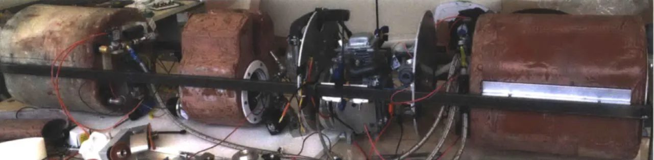
Figure 1-3 shows the full prototype in a partial stage of assembly. The fuel tanks are shown on the rail system with the snorkel and engine between them. The two tanks are split to balance their weight and prevent moment on the vehicle.
Figure 1-3: A full system view of the hybrid recharging power supply, with a fuel tank on each end and piping throughout the system.
Chapter 2
Design
2.1
System Requirements
The use of liquid fuel addresses the need for greater endurance in AUVs, but also poses a number of challenges for the design of the power supply. The system must stay neu-trally buoyant and be moment-free to prevent torque on the AUV during operation. The question of maintaining neutral buoyancy is the first challenge addressed in this thesis. As submersible vehicles, AUVs rely on an almost perfectly neutral buoyancy to stay at con-stant depth in the ocean without using power. If a AUV is less dense than water, the
AUV constantly tries to rise and must use power to maintain its depth. Conversely, if the AUV is too dense compared to the density of water, the AUV will sink and the vehicle
can easily be lost. The weight of most AUVs is set such that they are neutrally buoyant or slightly positively buoyant, and that weight normally does not change during operation. However, when the power system switches from one based purely on batteries to one that uses consumable fuel, neutral buoyancy becomes a significant concern. As the engine uses fuel and its exhaust is bubbled to the environment, the fuel management system must take on ballast to prevent a change in mass.
2.2
Theoretical Design
There are two main types of mass flow needed to provide fuel to the engine while maintaining a constant mass. First, the mass flow of fuel must be controlled such that gasoline can safely be delivered to the engine. Second, water and air must be brought into the system as ballast
to maintain the original mass of the fuel.
2.2.1
Fuel Delivery System
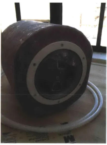
The fuel delivery system focuses on bringing gasoline from the fiberglass tanks to the engine. The fuel is stored in bladders within fiberglass tanks in order to minimize 'sloshing'. 33 liters of gasoline are initially held within the power supply in two bladders: one in the bow and one in the stern. By separating the fuel into two 16.5 liter capacity tanks, the weight is balanced and the vehicle does not tip while at rest.
Figure 2-1: Containment tank used to hold fuel bladder.
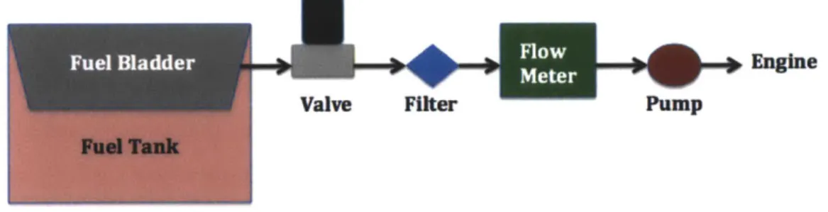
A fuel pump attached to the engine draws gasoline out of the storage bladder and
fiberglass tank through a normally closed solenoid valve. During engine operation, one of the two storage tanks will have its valve opened, allowing fuel to pass from one tank at a time to the engine. After passing through the valve, the fuel is filtered and then passes through a flowmeter. The flowmeter is used to determine how much fuel has been consumed, and to inform the operation of the buoyancy system that will be discussed in Section 2.2.2. The flowmeter measures the velocity of the fuel as it passes through by measuring the heat transfered from an internal heated component. The flow of fuel is very slow, flowing at about 8 mL/min, requiring the use of a special flowmeter. Most flowmeters do not read velocities that slow, nor would they normally have the accuracy required by the system. The SLQ-HC60 Milliliter Flow Meter for Hydrocarbons produced by Sensirion was chosen
Figure 2-2: SLQ-HC60 Milliliter Flow Meter for Hydrocarbons by Sensirion used to measure quantity of fuel consumed. Specifically designed for high accuracy at very low flow rates of
hydrocarbon fuel.
The gasoline then passes through stainless steel braided fuel hose made by Holley Per-formance Products to the fuel pump. The fuel pump came with the Honda engine chosen for the prototype power supply. It is powered by the vacuum in the crankcase and has no electrical components. This fuel pump draws fuel at a steady rate of 8 mL/min, and was experimentally found to be capable of drawing a vacuum in the fuel line to 14 psi below at-mospheric pressure. This fuel pump is hooked up directly to the engine, allowing fuel to be consumed by the engine and the exhaust of the reaction to be bubbled to the environment. Figure 2-3 shows a schematic of the mass flow of gasoline in the system.
Engine
Valve Filter
Pump
Figure 2-3: Mass flow of gasoline from fuel containment tanks to engine. Gasoline passes through a normally closed solenoid valve, a fuel filter, a flow meter, and a pump before reaching the engine.
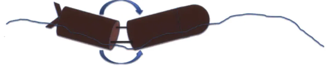
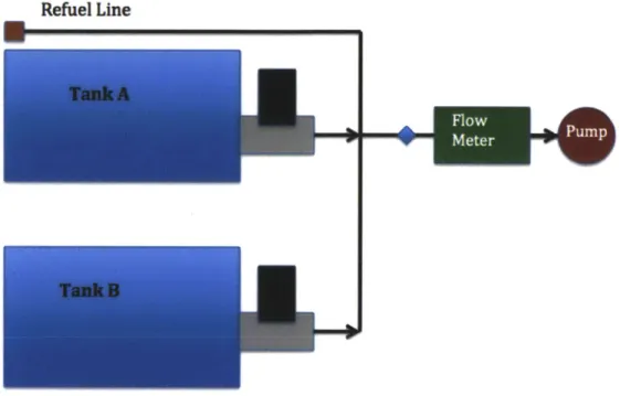
There are two tanks in the system, which will be called Tank A and Tank B. Each tank has its own fuel valve to control gasoline flow out of its bladder. The two tanks share the same gasoline filter, flow meter, and fuel pump, as well as the same refueling line. All of
these shared components are mounted on the face of Tank A, except for the fuel pump which is located near the engine. Figure 2-4 shows a schematic of how these two tanks connect.
Refuel Line
4r~
Figure 2-4: Connection of two tanks for fuel flow through system. Each tank has a separate fuel valve, but shares the fuel filter, flow meter, fuel pump, and refuel line.
A pressure sensor is also installed in the fuel line going to the engine as a safety
precau-tion to determine if fuel has run out. When a bladder of fuel is empty, the fuel pump will draw a vacuum in the line. The pressure sensor will recognize that vacuum and alert the computer system that the system is out of fuel. Finally, fuel vapor sensors will be installed on the face of the fuel containment tanks to determine if excessive gasoline vapor leaks into the larger system. With the design of the mass flow of fuel to the engine complete, the next question was how to maintain a neutral buoyancy during operation. A system to take on ballast to replace the lost mass of fuel was devised and will be detailed in the next section.
2.2.2 Buoyancy System
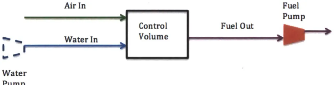
containment tanks were used as a control volume for the three liquids: fuel, water, and air. When fuel leaves the fiberglass tank as described in section 2.2.1, water and air flow into the control volume to take its place. Inside the fiberglass tank there is a fuel bladder, as described in section 2.2.1 and a water bladder. Because seawater is denser than gasoline, water will ultimately only fill 70 percent of the original volume of fuel, while maintaining the same mass. Throughout system operation, 70 percent of the original volume of fuel will be replaced by water with the rest filled in by air.
Air In Fuel
Pump
Control Fuel Out
Water In Volume
Water Pump
Figure 2-5: Mass-flow in and out of a control volume. A fuel pump draws fuel out of the control volume, which would be initially filled with fuel. Water and air then replace the lost volume in a proportion that maintains a constant mass.
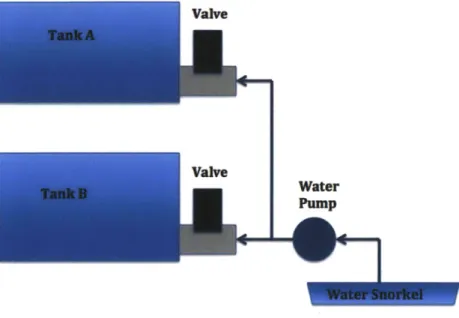
The water comes from the snorkel, the part of the power supply that interfaces with the environment. The water passes from the snorkel, through Tygon tubing, towards the water pump that is mounted on the face of Tank B. This water pump, Model 2022-RM1 designed by FlightWorks, Inc., is a gear pump designed to pull between 10 and 400 mL/min when run between 1 to 8 VDC. It was chosen for its relatively low flow rate capabilities, low power consumption, and small size. It will be run at 5V, giving a flow rate of 4 mL/sec. This flow rate was found experimentally.
From the water pump, the water then flows through a normally-closed valve into a water bladder within one of the containment tanks. A schematic showing the flow of water is shown in Figure 2-6.
The amount of water brought into the system is determined by limiting the time that the water pump is running and the valve for one of the tanks is open. The flow meter shown in Figure 2-2 is used to monitor how much fuel has been consumed so that the water pump can be run when necessary. For a set quantity of fuel, say 80 mL consumed over 10 minutes,
Figure 2-6: Flow of water from water snorkel, through water pump, to two fiberglass tanks.
the water valve will only be open for 14 seconds, bringing in 56 mL of water. Because the density of gasoline is 70 percent the density of water, those 56 mL of water replace the mass of the 80 mL of fuel. The different run times of the gasoline pump and water pump are dictated by their flow rates set for operation.
When the water is not being pumped into the system, air is allowed to passively flow into the control volume. During this time the vehicle does become slightly more buoyant as fuel is consumed and only air replaces it, but this effect is not problematic as the vehicle is surfaced during the operation of the power supply.
Only one tank is ever used at a given time, so that only two valves ever need to be open: one fuel valve and one of the ballast valves. These valves are made by SMC Inc. and allow for normally closed operation, only requiring power when open. While one tank is being accessed by the engine, the other will be closed off. Figure 2-7 shows the design of mass flow through the full system. The air and water snorkel are pictured, as are the two fuel
I
Fuel Flow
Fuel
Air
Sensor
Pump
Snorkel
Water
Legend:
Pump
Air
WaterWater
Fuel
Snorkel
Va ve
Figure 2-7: Piping diagram for the connection between the tank and the pump. Diagram highlights the water and fuel pumps, as well as the fuel flow sensor and valves. These electronic components are critical to the operation of the two tanks and their connection to the snorkel and engine.
2.3
Head Loss in Piping
To understand the types of losses that will be seen in the piping, the Reynolds number and related pressure drops were calculated for the gasoline and water piping systems. The velocity of the gasoline was first estimated by looking at the energy output and recorded efficiency of the engine, and backing out the input energy of fuel. The volumetric rate of fuel was later confirmed using a flow rate sensor. The volumetric rate of water was experimentally determined by testing a water pump that will be used for moving the water. The Reynolds number for both flows was well within the laminar range, allowing a simple calculation to be used to find the friction factor. Equation 2.1 shows the Reynolds number calculation.
Re = (2.1)
The friction factor in a laminar regime is calculated in Equation 2.2.
64
f
= Re (2.2)The losses due to bends and valves in the piping were summed to a total of a k value of
5.1. These values were found through tables referring to the 90-degree bends and ball valves,
where k is an experimentally determined constant that scales the relative pressure drop due to an obstacle in a pipe. The major and minor losses were found with the equations shown in Equations 2.3 and 2.4. Pmajor refers to the major losses due to friction against the walls of the pipe, while Pminor refers to the minor losses of the bends and obstacles in the system. The L term is the length of the tubing, D is the diameter of that tube, p is the density of the fluid, and V is the average velocity of that fluid.
f LpV2
Pmajor = 2D (2.3)
pkV
Pminor = 2 (2.4)
2
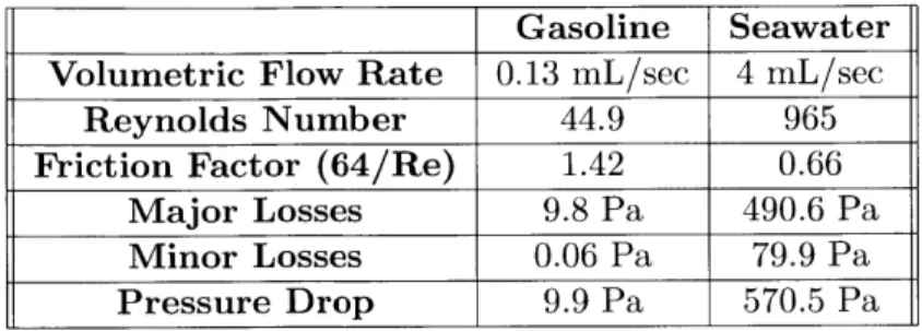
The final pressure drop for the flow of gasoline was approximately 10 Pa, and approx-imately 570 Pa for the water. The larger pressure drop in the water lines was due to the
Table 2.1: Head loss calculations for the flow of gasoline and seawater in the piping of the constant-mass fuel lines.
Gasoline Seawater
Volumetric Flow Rate 0.13 mL/sec 4 mL/sec
Reynolds Number 44.9 965
Friction Factor (64/Re) 1.42 0.66
Major Losses 9.8 Pa 490.6 Pa
Minor Losses 0.06 Pa 79.9 Pa
Pressure Drop 9.9 Pa 570.5 Pa
These losses are small due to the laminar, relatively slow flow rate of both the gasoline and the water in the system. The fuel and water pump can overcome these losses.
2.4
SolidWorks Design
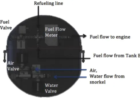
The fuel system, as well as the larger system, was modeled in SolidWorks to accurately determine the best orientation of the valves and sensors. To consolidate components within the space constraints, the valves and sensors were mounted to the face of the containment tanks. Due to the specific tubing solution with two interconnected fuel tanks, the piping of each tank is unique. As mentioned in Section 2.2.1, most of the electronic components for the fuel flow is mounted on the face of Tank A. The face of Tank B is therefore much more simple in the original design. As time went on, the addition of the water pump and design changes added complexity to Tank B as well. Figures 2-8 and 2-9 show the SolidWorks design of these two tanks.
Refueling line
I
Fuel flow to engine
Fuel flow from Tank B
p
Air,
Water flow from
snorkel
Figure 2-8: Design of Tank A. Shows three valves, as well as fuel flow meter. Also shows flow of ballast into tank and flow of fuel out of tank.
Fuel Valve
AirValve
Water Valve
Figure 2-9: Design of Tank B with three valves mounted to face. Image shows the water bladder at full capacity, or 70 percent of the original fuel volume.
These two tanks sit at either end of the power supply section for the AUV. A full SolidWorks model of the hybrid recharging system is shown in Figure 2-10. This would be only one segment of a larger AUV body. The shown model is 50 inches long and 12 inches in diameter.
Figure 2-10: A side view of the hybrid recharging power supply for use in AUVs. The fuel tanks sit on either end of the segment to balance the moment on the power supply. These fuel tanks connect to the snorkel (seen above and below the vehicle in fiberglass shrouds) and the engine. This segment would clamp into the rest of the REMUS vehicle.
Chapter 3
Construction and Assembly
3.1
Required Parts
To transition from a SolidWorks model of the setup to a physical working prototype, the first step was to locate and procure the necessary parts. This thesis will focus on the tubing and adapters necessary for the flow of fuel and ballast in the system.
For the ballast, a thread size of 1/4 inch NPT was chosen as a standard throughout the system, while for fuel the standard was set at 1/8 inch NPT. These thread sizes were chosen to conform to the threads built into the valves that were chosen for the ballast and fuel lines. The use of NPT threads allowed the threads to seal easily with the addition of Teflon tape or paste. The ballast tubing was sourced from McMaster, and was 1/4 inch ID silicon, flexible tubing. Its flexibility allowed for easy installation in the system, its size conformed to standards for pipe adapters, and its material properties were temperature resistant and tolerant of seawater. The ballast adapters were barbed hose fittings for 1/4 inch inner diameter hose along with the 1/8 inch NPT thread. These were used in conjunction with hose clamps to connect pipes with tubing in the system.
The fuel line used was 'Perform-O-Flex Hose' sourced from Holley Performance Prod-ucts. This hose integrated a rubber core with a stainless steel braided exterior, combining flexibility and easy installation with great temperature tolerance. This hose, as well as all of Earl's Plumbing equipment, was designed for use in racecars. The size 4-AN hose was chosen, with an internal diameter of 0.21875 inches and an outer diameter of 0.4375 inches. For the fuel adapters, the 'Auto-Mate Hose Ends' were chosen from Earls Plumbing to integrate with the size-4 Perform-0-Flex hose. The adapters were specifically designed for
the chosen hose, and were made to come on and off to ease installation, while guaranteeing a no-leak solution.
To connect the bladders inside of the fuel tank with the hosing outside, tank adapters were chosen that could be sealed on tank walls while allowing for 1/4 inch NPT fittings to attach on each end. The tank-wall fittings were made of nylon. These fittings were connected to 90 degree elbows that were 4-NPT on each end for the ballast, and 1/4 inch
NPT to 1/8 inch NPT for the fuel. These elbow pipes were made of aluminum, for their
strength in holding up the valves and their compatibility with water and fuel. The valves were then attached to these elbows, and attached to the tubing adapters on their other side. Three and four-way tees allowed the two tanks to be connected to one another and to the snorkel and engine respectively.
The fuel pump used to power the system came with the Honda engine that the larger team was adapting to work in a AUV. This pump had no electrical components, and only required a connection to the crankcase on the engine. It is believed that this crankcase provides a vacuum, which powers the fuel pump. The fuel pump is shown in Figure 3-1, along with a fitting that allows for connection to the fuel hose.
Figure 3-1: The fuel pump that came with the Honda engine being used for the prototype of the hybrid recharging power supply. The fuel pump has no electrical components, and is believed to operate using the vacuum created in the crankcase.
The valves used to control the flow rate came from the SMC Corporation. They were chosen for their low power consumption, their normally-closed setting so that if a failure
3.2
First Prototypes
The piping and valves were assembled separately from the containment tank, and were then mounted to the tank through the tank fittings. Every connection was sealed with Teflon tape if a ballast line and gasoline-rated Teflon paste if a fuel line. The tank fittings were sealed to the tank using silicon glue. Tubing adapters and the corresponding hoses were
then connected. Figures 3-2 and 3-3 show some early stages of assembly.
Figure 3-2: Initial design of fuel piping, valve, and tubing adapters assembled and checked for leaks. Fuel line adapters had not yet arrived, and ballast adapters had been used in the interim.
The valve assemblies were then mounted to the final containment tank through tank fittings. Figure 3-4 shows the valve assemblies as they were when initially attached to the final containment tank. While the tank fittings were able to support the weight of the smaller fuel valve, the water valve (in the bottom of the picture) was too heavy to maintain its position. This was expected, and valve mounts were manufactured and attached.
3.3
Completed Fuel Tanks
Several modifications were made during assembly. The design was adjusted to accommodate the bend radius of the fuel line. Right angle bends were added to the 4-way cross on Tank
A for easier routing. Additionally, due to complications with the snorkel design, the air
line was removed and air from within the vehicle was allowed direct access to the air valve. The fuel filter that was required before the flow meter needed smaller fuel tubing than the standard chosen for the system. Adapters were made to connect this smaller fuel line to the
Fuel Valve
Air Valve
-Water Valve
Figure 3-3: Early prototype: valves and piping resting on early version of containment tank (not mounted or sealed). Fuel line adapters had not arrived, and were approximated with the ballast hose adapters. General spacing was confirmed to be satisfactory.
Fuel Valve
Air Valve
Water Valve
Figure 3-4: Initial tubing connected on final containment Tank A. Fuel, air, and water valves all attached through tank fittings. Ballast lines connected. Fuel valve attached through tank fitting, fuel line adapters connected.
larger system, and the fuel filter and flow meter were installed on the fuel line. Additionally, valve mounts were added to all three valves to ensure stability. Figures 3-5 and 3-6 show the final construction of the fuel Tank A.
Fuel Valve
Air Valve
Water Valve
W Fuel to engine
Refueling line
(pbiggtctat other end)
Fuel to Tank B
Fuel flow meter
Figure 3-5: Tank A fully fitted. Valves are on valve mounts to ensure stability. Right angle bends ease installation of fuel lines. A fuel filter and fuel flow sensor are installed on the fuel line to the engine. A fuel line is also connected to Tank B, and another routed for refueling.
Refuel Line
Figure 3-6: Side view of Tank A showing the refuel line passing to the outside of the rails to allow for access to the fuel system from outside of the tube. Tank B has the same set up of valves, but a non-symmetrical piping system.
A single fuel line comes from Tank B, passing to Tank A. Tank B, however, has more of
the water piping, as the water pump is mounted to the face of Tank B. The water line from the snorkel goes to the water pump at Tank B before routing to the bladder of either Tank B or Tank A. Tank B also holds some extraneous equipment, such as the pressure sensor that determines if a fuel bladder is empty and the fuel vapor sensor. Figure 3-7 shows the setup for Tank B.
These two tanks connect on a rail system that supports all components of the power supply. The fuel and ballast lines connect to the snorkel and engine along these rails, along with connecting the two fuel tanks to one another. Figure 3-8 shows a full-length view of the vehicle.
Fuel Valve Fuel Line to Tank 1 Water Valve Pressure Sensor -" Water Pump
Figure 3-7: Tank B shown with fuel and water lines fully fitted. Fuel line shown routed to Tank B, along with a pressure sensor to detect the depletion of fuel. Water line routed to water pump and snorkel, and to Tank A. Air valve had not yet arrived. Fuel vapor sensor also installed on face of tank.
Figure 3-8: Full-length of setup. Two fuel tanks connected to one another with fuel and ballast lines. Snorkel and engine also shown, connected to the tanks through the ballast and fuel lines respectively.
Chapter 4
Testing
Each component of the system was tested individually before assembly to ensure proper operation, and as a whole after assembly had taken place. Specifically, the connections were tested for leaks and the pumps were tested to their determine flow rate and pressure head.
4.1
Leak Detection
The first tests were run on the valves and piping. The goal of these tests was to make sure the valves were operating normally, and to visually check for leaking in the connecting threads. A water bladder was connected to each valve using a barbed hose adapter. The water bladder was squeezed while the valve was off or closed to look for leaks. No leaks were seen on any of the connections. The valves were then opened by connecting them to a 12V power supply, and water was seen to easily flow through the valve. Figure 4-1 shows an example of one of these tests, using a test water bladder.
4.2
Fuel Pump Characterization
The next test was done to characterize the fuel pump that came with the engine. Little was known about the fuel pump prior to the test, except that it operated through a vacuum mechanism from the engine. To test the fuel pump, fuel tank 1 was connected to the fuel pump, which was in turn connected to the engine. The pressure sensor was inserted into the four-way adapter on tank 1, and was hooked up to a multimeter. The fuel valve and
Figure 4-1: Leak-testing the water valve assembly. Water was squeezed through assembly while valve was open (12V were supplied across the two leads). Water flowed through the valve easily, and no leaks were seen on threads or hose fitting.
water valve were opened, with the ballast line simply running into freestanding water. The engine was started, automatically causing the fuel pump to begin operation. The engine was put under full load and continued to run smoothly off of the fuel tank, indicating that under normal operation, the fuel pump was able to overcome the head losses in the fuel hose.
In order to better understand the fuel pump and its response to emergency situations, both valves were then closed and access to additional fuel was cut off. The engine continued to run throughout the experiment off of the fuel remaining in the fuel hose. However, as the engine consumed fuel, the fuel pump pulled a vacuum in the fuel line. The pressure sensor read that the pressure at the fuel valve flattened out at -160mV. Using the appropriate conversion, this equates to -14.2 psi. This is close to a complete vacuum, and the fuel pump was not able to further decrease the pressure. Rather than the pump or engine shutting down, the pressure likely leveled out at this level due to leaks whereby air came into the line through the connection between piping and hose. The fuel pump is able to draw significant amounts of pressure, indicating that small blockages or pressure effects from dynamics in the ocean should not affect engine performance. Figure 4-2 shows the setup of the fuel tank used to test the fuel pump. The pressure sensor is shown in line with the fuel hose.
Figure 4-2: Tank 1 in preparation for the fuel pump test. The pressure sensor is inserted into the four-way adapter by the fuel line to characterize the effects of the fuel pump. The fuel and water valves (top and bottom) are open, allowing fuel to flow out and (theoretically) water to flow in.
However, the secondary requirement was to remain at a constant mass throughout operation, and it was this requirement that motivated the majority of the design. With the inclusion of a water pump and the development of a control system that operated the valves and pump together with information from the fuel flow sensor, the fuel tanks were able to stay at a constant mass while delivering fuel. The water pump was tested to determine the calibration between voltage and mass flow.
4.3
Water Pump Calibration
The water pump was given 5V from a power supply, mimicking the 5V rail that will power it in real conditions, and the resulting volumetric flow rate was recorded. The volumetric flow rate was found using a graduated cylinder and a timer. The timer was started when the pump had filled 5 mL and stopped when the water level reached 45 mL. The beaker was then emptied and the test was repeated. Figure 4-3 shows the full experimental setup. For normal flow conditions, the average volumetric flow rate was found to be 4.1 mL/sec, while with restricted flow the average flow rate was found to be 3.7 mL/sec. To restrict the
Water pump Power Supply at 5v Graduated cylinder
Figure 4-3: Setup for testing the water pump flow rate. The water pump was run at 5V. Water was pumped from a cup to water a graduated cylinder. The time it took for 40 mL of water to be transferred was recorded and the pump was found to operate at approximately 4 mL/sec.
flow, the output line was closed fairly tightly with a clamp, in an attempt to model head
loss in the system. Figure 4-4 shows the clamped output line.
Figure 4-4: The output line of the water pump calibration.
clamped to add head loss into the piping
With a calibrated water pump, the fuel system is ready to deliver fuel to the engine while maintaining a constant mass. The water pump brings water into the system at 4 mL/sec, while the fuel pump draws fuel out at 8 mL/min. The water pump will be run for 14 seconds for every 10 minutes that the fuel pump operates in a given tank to bring in the same mass of water as consumed mass of fuel. The water pump is connected such that it can pump water into either tank at a steady rate. The working water pump is the last piece of the puzzle, allowing for constant mass fuel tanks.
Chapter 5
Conclusion
In the fall of 2011, Lincoln Laboratory asked a class of undergraduates at MIT to increase the endurance of autonomous underwater vehicles (AUVs) while maintaining their maneu-verability. The class designed a hybrid recharging system that could be inserted as a segment of the larger REMUS 600 vehicle by Hydroid. A hybrid recharging system takes advantage of the high power density of liquid fuel and the convenience of lithium ion batteries.
The use of liquid fuel addressed the concerns of endurance while still giving the system enough power to move at high speed. However, liquid fuel brought up new concerns, which are addressed by the fuel tanks described in this thesis. The fuel distribution system safely stores and delivers gasoline from two separate fiberglass tanks to the engine, while bringing in ballast to maintain a constant mass.
This thesis covers the design of the mass flow through the fuel system and the assembly of two prototype fuel tanks. The thesis describes designing the theoretical flow of mass in the system, determining the types of valves and pumps needed, modeling the physical system in SolidWorks, assembling the system on a test setup, and testing the two pumps. The prototype demonstrates that a fuel tank can stay at constant mass during operation while safely handling gasoline, air, and water.
Constant-mass fuel tanks have large potential within the realm of underwater au-tonomous vehicles. The fuel tanks built for this thesis specifically address the burning of gasoline on board a torpedo-shaped AUV, but the approach can be used for other geometries and other fuels. By addressing the problem of buoyancy changing over time, constant-mass fuel tanks open up the use of liquid and solid fuel on underwater autonomous vehicles,
Appendix A
Part Information
A.1
Fuel Flow Sensor Specifications
I
Ii
$ 4 I 5 9 -0 -40 -W 0 20 ) Flow nin]P* 60 s0 1 12Figure A-1: Characteristic behavior of flow meter, shown here for ethanol. Most linear relationship a between output voltage and flow at low flow rates: 0-8 mL/sec.
0
30
I I3
Figure A-2: Dimensions of flow meter
N
'I I
7A4 3 1)
SPECIFICATIONS: Performance
Flowrate (@8.0VDC): 400 mL/mm
Max. Pressure: At least 2.0 bar (30 psi) Continuous Electrical
Motor: 8.OVDC Brushed, Reversible. Connection Type: Solder Tabs Permissible Fluid Options:
Kerosene, Jet-A, JP-8, Diesel, or Equivalent
Contact Flight Works, Inc. for compatible construction materials for your particular fluid.
Construction Options:
Body: Hard Anoized Aluminum, Stainless Steel
Gears: 416SS, 416SS Hardened, 420SS Hardened, PEEK Plastic Seals: Viton, Buna Nitrile, EPDM
Ports: M3 x 0.5mm
Fittings: Barb for 3mm I.D. Tubing, Push-in for 3mm O.D. Tubing, 90' Swivel Elbow, Compression
Weight: 35g Operation:
Prming: Pump will dry prime. Do not run dry for more than 30 seconds Required Filtration: 50 Micron Pre-Pump Filter (Flight Works, Inc. P/N 6065-4) Mounting: Stainless Mounting Bracket Included w/ Rubber Grommets Contact Flight Works, Inc. for any further customization questions.
REVISIONS
REV DCR# ZONE DESCRIPTION I BY DATE
N/C NO CHANGE |MO 1/9/2012
-- 26 -
S
- 45.12
20
SEE SHEET 2 FOR PERFORMANCE DATA
GENERAL NOTES: (UNLESS OTHERWISE SPECIFIED)
1. ALL DIMENSIONS IN MILLIMETERES UNLESS OTHERWISE SPECIFIED
NOTE:
"ay" "ar "depedin " nth s*" st'e "ai n ht a e nte arps red.
Fght Work makes no warntis expresse oriplid conc irn isg the mimbidiy orftesoh is prdc formy particula purpos, Iti
fue aepndity of tecstuomer to determine tha the product is safe,
l , tcically f ,,b th ,r 7 6 5se.
8 7 65
ULESS OTHERWIS SPELFIERS DASH NO.
-T RALt E REX11.025 .XXXtu12 APPROVALS TTLRNUT .002 DRAWN SURFACE FINISH: 32 RMS M. OKADA
CHECKED
MATERIAENOTES DO NOT SCALE DRAWING
DATE FLIGHT 912 WORKS, In. MODEL NO. A SCALE / 4 3 2 1 E D C B A 21 .95 34 A N/C SH EET I OF 2 7 6 5 4 3 2
1
Works Cited
1. Button, Robert W., John Kamp, Thomas B. Curtin, James Dryden. A Survey of
Missions for Unmanned Undersea Vehicles National Defense Research Institute. 2009. 2. Earls Performance Plumbing. 2012. http://www.holley.com/Index.asp?division=Earls.
3. Flightworks Incorporated, 2012.
http://www.flightworksinc.com/products/pump/Product%20Data%2Sheet-2022-RM1.PDF 4. Heiszwolf, Johan J. Submarine Dive Technology. 2001.
www.heiszwolf.com/subs/tech/tech01.html
5. McMaster-Carr Catalog, 2012. Mcmaster.com.
6. Ocean: Monitoring and Understanding, National Oceanic and Atmospheric
Adminis-tration. United States Department of Commerce. 2011. http://www.noaa.gov/ocean.html
7. REMUS 600: Autonomous Underwater Vehicle, Hydroid. 2011.
8. Tang, Y., "Dynamic Response of Tank Containing Two Liquids," J. Eng. Mech. 119
(3), 531-18 1993.
9. Tangirala, S., and J. Dzielski, "A Variable Buoyancy Control System for a Large AUV," Oceanic Engineering, IEEE Journal of 32 (4), 762-771 2007.