HAL Id: hal-00525088
https://hal.archives-ouvertes.fr/hal-00525088
Submitted on 11 Oct 2010HAL is a multi-disciplinary open access
archive for the deposit and dissemination of sci-entific research documents, whether they are pub-lished or not. The documents may come from teaching and research institutions in France or abroad, or from public or private research centers.
L’archive ouverte pluridisciplinaire HAL, est destinée au dépôt et à la diffusion de documents scientifiques de niveau recherche, publiés ou non, émanant des établissements d’enseignement et de recherche français ou étrangers, des laboratoires publics ou privés.
mobile robot
N. Bouton, R. Lenain, Benoît Thuilot, P. Martinet, M. Berducat
To cite this version:
N. Bouton, R. Lenain, Benoît Thuilot, P. Martinet, M. Berducat. New active safety device dedicated to light all-terrain vehicle stability: Application to quad bike and off-road mobile robot. AgEng 2010, International Conference on Agricultural Engineering, Sep 2010, Clermont-Ferrand, France. 8 p. �hal-00525088�
New active safety device dedicated to light all-terrain
vehicle stability: Application to quad bike and off-road
mobile robot
N. Bouton
1, R. Lenain
1, B. Thuilot
2, P. Martinet
2, M. Berducat
11 Cemagref – Unité TSCF, 24 av. des Landais, BP 50085, 63172 Aubière Cedex. France. 2 LASMEA, 24 av. des Landais, 63177 Aubière Cedex. France.
Abstract
According to their specific geometric and dynamic characteristics (small weight, huge reachable speeds…), All-Terrain Vehicles (ATVs - as quad bikes) and off-road mobile robots are very compact and driveable. They permit to realize extra agricultural tasks (spreading, spraying…) in an easier way than using once more a heavy farm tractor. However such vehicles require highly accurate control laws, able to preserve their stability even at high speed.
In this paper, the prevention of off-road vehicle and mobile robot rollover are addressed by using a new active safety device. It consists in using Predictive Functional Control (PFC) so as to compute, on-line, the maximum vehicle velocity, compatible with a safe motion over some horizon of prediction, and can be applied, if needed, to the vehicle actuator to prevent from rollover. The capabilities of the proposed device are demonstrated and discussed thanks to both advanced simulations and real experimentation.
1. Introduction
Off-road mobile robots and light All-Terrain Vehicles (ATV) appear as an interesting solution so as to answer social needs in various fields of application ([1] - farming, surveillance, military activities, etc). However, if many potential devices can take benefits of innovation in this area (increasing work accuracy, decreasing the level of risk), such applications require highly accurate control laws, able to preserve vehicle stability even at high speed. Indeed, in off-road mobile robot context, the complexity and the variability of the encountered phenomena have to be tackled to ensure both accuracy and security. Nevertheless, if numerous systems have been developed for road vehicles (active suspensions, active steering [2], steering and braking control [3] and [2]), they appear to be poorly relevant for fast off-road motion context (since they do not adapt to varying grip conditions). Consequently, specific safety devices have to be designed for off-road mobile robots.
The first step in the development of such devices is the design of a rollover indicator dedicated to off-road mobile robots. Previous work [4] has shown that the Lateral Load Transfer (LLT - [5]) is a very relevant criterion. Its advantages, with respect to other stability metrics such as the Static Stability Factor (SSF) [6], the force-angle measurement criterion [7] or the Zero Moment Point (ZMP - proposed usually to investigate humanoid and mobile robot stability, [8]) are that, on the one hand it does not demand for a huge and expensive perception system, and on the other hand it is not dependent on some thresholds particularly difficult to tune in outdoor environment.
In order to use properly such a metric in an off-road context, grip conditions have to be known. A new observer has been proposed in [9]. It consists in the on-line adaptation of tire cornering stiffnesses, representative of grip conditions, based on a vehicle dynamic model. Then, using the adapted parameters, it permits to access the sideslip angles to be entered into the algorithms proposed in [10], so as to control robot motion with a high accuracy whatever ground conditions, vehicle velocity (up to 40km/h) and the shape of the path to be
followed. Thanks to the estimation of cornering stiffnesses, this observer appears also to be relevant in the on-line computation of the Lateral Load Transfer and finally for the design of stabilizing algorithms.
In this paper, this indicator is used as a basis for designing an active anti-rollover device dedicated to mobile robots. More precisely, the maximum vehicle velocity ensuring that the LLT remains within a safety range over the horizon of prediction is estimated on-line, and can then be applied to the vehicle actuator in order to avoid imminent rollover. The algorithm relies on Predictive Functional Control principle (PFC - [11], [12]), so that off-road mobile robot dynamic features can be accounted.
The paper is organized as follows: vehicle modeling in presence of slidings used to develop the control device is presented. Then, previous work on path tracking is recalled as well as the notion of Mixed observer used for the estimation of grip conditions (cornering stiffnesses) and sliding parameters (sideslip angles). Next, Predictive Functional Control principle is applied to design vehicle velocity control law in order to guarantee lateral dynamic stability of mobile robots on slippery ground. Finally, experimental results are reported to validate the relevancy of the proposed approach in situations where lateral rollover is imminent.
2. Vehicle modelling
2.1.
Vehicle dynamic model
In order to describe the rollover of a mobile robot, its motion in yaw and roll representations has to be known. Then, two representations are here introduced: one is a yaw representation (Figure 1) (also used to develop the Mixed observer described in Section ) and the other one is a roll representation (Figure 2). The yaw model, also used for path tracking and sliding estimation aims at describing the overall vehicle motion on the ground and consists of an extended bicycle model of the mobile robot. It is used to estimate some vehicle motion variables (as the lateral acceleration of the vehicle center of gravity) and sideslip angles. These variables are then injected into the second part of the dynamic model, characterized by a roll 2D projection (shown on Figure 2)), used to compute roll angle, roll rate and the LLT.
Figure 1 : Yaw projection of the dynamic model Figure 2: Roll projection of the dynamic model Motion equations issued from the yaw projection shown in Figure 1 require analytical expressions of lateral forces Ff and Fr. Therefore, as explained in [13], a simple linear tire model has been considered. It can be expressed as:
(.) F (.) F r f = = r r f f C C
α
α
(Eq.1)This model requires only the knowledge of αf and αr and the front and rear cornering stiffnesses Cf(.) and Cr(.) supposed to be slow varying. In order to reflect the variable grip conditions, these two parameters are on-line estimated thanks to the Mixed observer detailed in Section . Only one parameter is then needed, contrary to classical tire models such as the celebrated Magic formula [14].
2.2.
LLT definition
The general expression of the Lateral Load Transfer (LLT) (see [15]) is:
F F F F LLT n2 n1 n2 n1 + − = (Eq.2)
Clearly, a rollover situation is detected when a unitary value of |LLT| is reached, since it corresponds to the lift-off of the wheels on the same side of the vehicle. Here, the vehicle behavior will be considered as hazardous when LLT reaches the critical threshold LLTlimit (| LLT|> LLTlimit).
2.3.
LLT dynamic equation
In order to extract normal force expressions from the roll model (see Figure 2), the following assumptions have been made:
• The entire vehicle mass is suspended, which implies insignificant non-suspended mass (essentially tires),
•
The suspended mass is assumed to be symmetrical with respect to the two planes (z2, y2) and (x2, z2). The inertial matrix is then diagonal in the roll frame R2(x2,y2,z2),•
Sideslip angles β, αf and αr are assumed to be small (corroborated by experiments),•
As a consequence, the vehicle velocity u at roll center can be considered to be equal to the rear axle one (i.e. u≈v).Using these assumptions, the LLT indicator can be evaluated from the Newton Euler formalism applied to the overall system. More precisely, variations of the roll angle φv, and normal forces Fn1 and Fn2 can be derived as:
+
−
+
+
+
+
=
s i n (
)
s i n (
)
c o s (
)
s i n (
)
c o s (
)
c o s (
)
)
c o s (
1
2
2
v
v
r
v
r
v
v
v
v
v
m h
b
k
u
u
u
h
h
h
ϕ
ϕ
ϕ
β
β
β
β
ψ
ϕ
ψ
ϕ
ϕ
ϕ
ϕ
(Eq.3)
+
−
+
−
−
=
+
)
sin(
)
cos(
)
sin(
)
(
1 2 2 r v r v v v v v v n nmh
b
k
g
h
h
m
F
F
ϕ
ϕ
ϕ
ϕ
ϕ
ϕ
ϕ
(Eq.4)(
)
(
)
[
cos( )sin( ) sin( )( )]
2 ) ( 2 1 2 2 1 n x v z y v v v n n n I I I h F F c F F − = ϕ + − ψ ϕ ϕ − ϕ + (Eq.5)
In order to infer the roll angle and the LLT from (4)-(5), the global sideslip angle and the yaw rate are both required. Since the former one cannot be measured, an observer has been designed and is presented below.
3. Mixed observer
As explained in the previous paragraph, both the dynamic modeling used to compute LLT and the path tracking algorithm require an estimation of sliding parameters. Then, an indirect estimation of dynamic model parameters is mandatory. Since appropriate sensors are missing, this is achieved in several steps, using different level of modeling (kinematic and dynamic). This multilevel estimation is gathered in the so called Mixed observer detailed in [9]. Its general principle is described in Figure 3. The observation loop consists of successive steps, each one relying on the variable supplied by the preceding step. The three blocks shown in Figure 3 are described below:
• A preliminary extended kinematic observer (red dashed box) is first used to supply relevant tire sideslip angle estimation at low speed.
• Then, the parameters obtained by the kinematic observer are used in the cornering stiffness observer (green dotted box) where the cornering stiffnesses are on-line adapted with the aim of reflecting grip condition variations.
• Finally, with the adapted parameters, a dynamic sideslip angle observer (blue dashed dotted box), derived from standard observer theory, is applied in order to get relevant sideslip angles estimation at high speed and whatever the grip conditions.
The sliding angle estimates supplied by such an observer are relevant to compute LLT and to develop anti-rollover predictive control laws as detailed below.
Figure 3 : Scheme of the path tracking controller
4. Predictive functional control of the vehicle
In order to avoid the rollover risk, the limitation of the LLT (i.e. LLT≤critical threshold value – here, LLT≤0.8) through the control of the ATV speed is here investigated. The idea is to compute at each time the velocity leading to this LLT threshold one moment in the future. This value can then be considered as the maximum admissible velocity (denoted vmax in the sequel) to avoid lateral rollover situation.
The global scheme is depicted on the following figure:
Figure 4 : Predictive velocity control of an ATV
The computation of the maximum velocity, detailed is represented by the block "Predictive control". Relying on this variable, the speed limitation process consists on the following steps:
1. The "Min" block supplies the rear axle linear velocity control input vinput to be applied to the vehicle. This variable is deduced from the comparison between the velocity specified by the pilot (or desired in the case of autonomous off-road mobile robot) vpilot and the maximum velocity vmax: vinput=min(vpilot,vmax)
2. The measurements shown in Figure 4 are then used to estimate on-line the sliding parameters and the cornering stiffnesses thanks to the Mixed observer described in Section ,
3. Then, stiffnesses (from the Mixed observer), the measured rear axle linear velocity and the measured steering angle are reported into the vehicle roll model in order to compute the roll angle
ϕ
v and the LLT (see Section ),4. Finally, the roll angle
ϕ
v, the sliding parameters and the steering angle are processed in the ``Predictive Control'' block in order to supply the maximum velocity vmax.In order to anticipate (and then avoid) hazardous situations, the computation of vmax is based on the Predictive Functional Control (PFC) formalism, detailed in [11] and [12] by using the roll angle evolution supplied by (3). The vehicle velocity is then viewed as a control variable and vmax is designed in order to ensure the convergence of the LLT to the value 0.8.
5. Results
5.1.
Advanced simulation
Figure 5: Virtual quad bike
An advanced simulation has been done with the virtual quad bike described on Figure 5Figure 1, where rear axle linear velocity control strategy has been applied. The velocity and steering angle specified by the pilot during the simulation are depicted on Figure 6.
Figure 6: Pilot desired velocity and steering angle Figure 7: Velocity control and Lateral Load Transfer results Figure 7 shows the time evolution of the velocity specified by the pilot vpilot (in blue dash-dotted line), the maximum velocity vmax (computed with the PFC algorithm, in red solid line)
and the rear axle velocity vinput to be applied to the vehicle (in green dashed line). From t=0s to t=10s, the virtual quad bike is either moving according to a straight line or the steering angle value is low (δ<3°). Therefore the maximum velocity cannot be computed and is then set to 14m/s. After t=10s, the velocity to be applied vinput is equal to the minimum of vpilot and vmax. As a result, first, vinput is equal to vpilot, then, between t=27.6s and t=53.7s, vinput = vmax, because vpilot is too high with respect to the steering angle values, even when the steering angle is decreased from 10° to 7.5°. Finally, after t=53.7s, vpilot has been reduced, so that vpilot can again be actually applied.
Figure 7 also shows the time evolution of the LLT measured on the virtual quad bike when respectively vinput (black solid line) and vpilot (red dashed line) are applied. In the last case, after t =29s, the vehicle rollovers (since LLT =1). Contrarily, when vinput is applied, the LLT safely converges to the LLT threshold value (LLT = 0.8) when vpilot exceeds vmax. Vehicle rollover has then satisfactorily be avoided, while keeping vehicle velocity as high as possible in such a situation.
5.2.
Real experiment
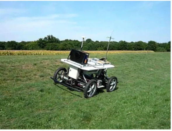
A real experiment has been performed with the robot described in Figure 8. It consists of an electric off-road vehicle. The main exteroceptive sensor on board is a Dassault-Sercel dual frequency ``Aquarius 5002'' RTK-GPS receiver, which can supply an absolute position accurate to within 2cm, at a 10Hz sampling frequency. In addition, a gyrometer supplying a yaw rate measurement accurate to within 0.1°/s is fixed on the chassis as well as a steering angle sensor and a Doppler radar.
Figure 8 : Experimental platform
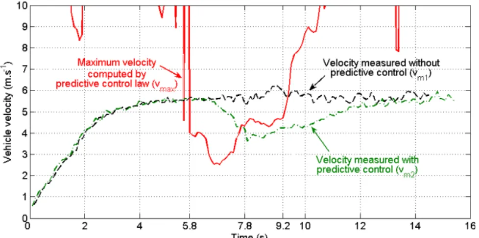
Then, two tests have been performed: the first one consists in using path tracking control without predictive control and a constant vpilot=vd=6m/s velocity. The second test consists in using the predictive functional control algorithm dedicated to LLT limitation and LLTlimit=0.35. Figure 9 shows the time evolution of the measured velocity vm1 when path tracking is done without velocity control (vm1≈vd≈6m/s after settling time) in black dash-dotted line, the maximum velocity vmax (computed with the PFC algorithm, in red solid line) and the rear axle velocity vm2 measured on the vehicle (in green dashed line) when velocity control is used. As described in Section , vm2 is supposed to be equal to the minimum of vd and vmax. From t=0s to t=5.8s, vm2 is equal to vd. Then, between t=5.8s to t=9.2s, during the curved part of the reference path, the velocity control variable applied to the vehicle is the maximum velocity given by the predictive functional control algorithm. However, due to the delay introduced by the velocity actuator, the measured velocity vm2 is satisfactorily superposed with vmax only beyond t=7.8s. Finally, after t=9.8s, vmax is superior to the desired velocity, so that vd can again be actually applied and after settling time (t=13s), the measured velocity vm2 converges to vd.
Figure 9 : Velocities comparison during real experiment
Figure 10 shows the time evolution of the Lateral Load Transfer of the vehicle. LLT without prediction (LLT obtained when vm1≈vd is measured on the vehicle) is depicted in black dash-dotted line and the LLT measured with the predictive control is depicted in red solid line (LLT obtained with vm2, i.e. when the minimum of vd and vmax is applied to the vehicle). In this figure, the LLT obtained with vm1 is largely superior to LLTlimit fixed here at 0.35. On the contrary, after the settling time (after t=8s), the LLT measured with vm2 satisfactorily converges to the LLTlimit. Indeed, between t=6s and t=8s, the LLT measured is superior to the LLTlimit, since the velocity actuator introduces a delay between the velocity control variable, here equal to the maximum velocity vmax computed via PFC algorithm and the real velocity of the vehicle vm2, as explained in the previous paragraph and which can be seen on Figure 9. Finally, when vm2≈vmax, the LLT measured is equal to 0.35.
Figure 10 : Lateral Load Transfer measured
6. Conclusion
This paper proposes a new safety device, based on Predictive Functional Control formalism, dedicated to off-road mobile robots operating on a natural and slippery ground. First, previous work on path tracking control, built from both adaptive and predictive control laws, has been recalled. Sliding effects have been taken into account according to a mixed kinematic and dynamic observer adapting on-line the tire cornering stiffnesses of the front and rear tires. It enables to take into account the non-linear behavior of the tire and the variations in grip conditions when computing the sideslip angles. Then, these sliding parameters are introduced into a predictive functional control law, based on a vehicle dynamic model, so as to compute the maximum velocity admissible by the robot, ensuring
that the LLT indicator never exceeds the rollover threshold (i.e. |LLT|< LLTlimit). Real experiments, carried out with a high speed mobile robot, demonstrate the applicability and the relevancy of the proposed control strategy to avoid rollover situations and ensure path tracking trajectory.
Future work will be dedicated to reduce the delay introduced by the velocity actuator. Indeed, it has been highlighted that the velocity measured on the vehicle differs from the velocity control variable. Therefore, another predictive control law based on the velocity actuator characteristics is under development so as to eliminate the delay.