HAL Id: hal-01952611
https://hal.archives-ouvertes.fr/hal-01952611
Submitted on 12 Dec 2018
HAL is a multi-disciplinary open access
archive for the deposit and dissemination of
sci-entific research documents, whether they are
pub-lished or not. The documents may come from
teaching and research institutions in France or
abroad, or from public or private research centers.
L’archive ouverte pluridisciplinaire HAL, est
destinée au dépôt et à la diffusion de documents
scientifiques de niveau recherche, publiés ou non,
émanant des établissements d’enseignement et de
recherche français ou étrangers, des laboratoires
publics ou privés.
Kinetics of CO2 Capture by Hydroquinone Clathrates
Romuald Coupan, Jean-Philippe Torré, Christophe Dicharry, Mehrdji Hemati,
Frédéric Plantier
To cite this version:
Romuald Coupan, Jean-Philippe Torré, Christophe Dicharry, Mehrdji Hemati, Frédéric Plantier.
Ki-netics of CO2 Capture by Hydroquinone Clathrates. Industrial and engineering chemistry research,
American Chemical Society, 2018, 57 (24), pp.8172-8182. �10.1021/acs.iecr.8b01462�. �hal-01952611�
OATAO is an open access repository that collects the work of Toulouse
researchers and makes it freely available over the web where possible
Any correspondence concerning this service should be sent
to the repository administrator:
[email protected]
This is an author’s version published in:
http://oatao.univ-toulouse.fr/21103
To cite this version:
Coupan, Romuald and Torré, Jean-Philippe and Dicharry, Christophe
and Hemati, Mehrdji
and Plantier, Frédéric Kinetics of CO2 Capture
by Hydroquinone Clathrates. (2018) Industrial & Engineering Chemistry
Research, 57 (24). 8172-8182. ISSN 0888-5885
Kinetics of CO
2
Capture by Hydroquinone Clathrates
Romuald Coupan,
†Jean-Philippe Torré,
*
,†Christophe Dicharry,
†Mehrdji Hemati,
‡and Frédéric Plantier
§†
Laboratoire des Fluides Complexes et leurs RéservoirsIPRA, UMR5150, CNRS/TOTAL/UNIV PAU & PAYS ADOUR, Avenue de l’Université, 64000 Pau, France
‡
Laboratoire de Génie Chimique (LGC), ENSIACET, INPT, Université de ToulousePaul Sabatier, CNRSUMR 5503, 5 rue Paulin Talabot, BP 1301, Toulouse F-31106, France
§
Laboratoire des Fluides Complexes et leurs Réservoirs-IPRA, UMR5150, CNRS/TOTAL/UNIV PAU & PAYS ADOUR, Allée du parc Montaury, 64600, Anglet, France
ABSTRACT: Organic clathrates formed by combining hydro-quinone (HQ) and CO2could offer very interesting prospects in the
near future, particularly in the field of CO2 capture and storage.
However, one of the main limitations hindering the large-scale deployment of this type of clathrate-based technology is the slow enclathration kinetics. Our experiments, performed at different pressures (1.5, 3.0, and 4.5 MPa) and temperatures (298, 323, and 348 K), with HQ in different forms (HQ powder, HQ pellets, and HQ−silica composites, each different in nature and in terms of pore size and HQ content) demonstrated that (i) an increase in both pressure and temperature enhances the enclathration rate, (ii) the textural properties of HQ significantly impact kinetics, and
composite materials remain the most efficient for improving HQ clathrate formation kinetics.
■
INTRODUCTIONCarbon dioxide (CO2) is one of the most common
anthropogenic greenhouse gases in terms of its concentration in the atmosphere. If nothing is done to curb the amount of CO2currently released, global warming will continue, inducing
dramatic changes in the global climate system.1In the transition period from a fossil-fuel to a low-carbon world, one of the most critical technological challenges is to develop efficient, environ-mentally friendly, and low-cost CO2 capture technologies.
Despite the considerable academic and industrial R&D efforts already focused on this subject over the past decade,2the high costs and energy penalty of many solutions (e.g., chemical absorption using amines) remain prohibitive, meaning that CO2
capture processes still cannot be deployed on a large scale for industrial applications other than natural gas treatment or chemical production. Intensive research efforts must therefore be maintained to test innovative ideas and develop emerging technologies such as the use of clathrates for CO2separation.
Gas clathrates are supramolecular entities composed of a network of host molecules forming cages or channels capable of stabilizing different types of gas molecules in well-defined thermodynamic conditions. If the host molecule is water, clathrate hydrates are the host−guest compounds, commonly called gas hydrates. If the host molecule is organic, the host− guest compounds in this case are organic clathrates. Among the portfolio of new solutions on offer to separate CO2 from
gaseous compounds, technologies based on clathrate hydrates
were initially presented as a gas separation technique potentially more advantageous than conventional separation methods, such as cryogenic fractionation, gas absorption, adsorption processes, or membranes.3,4 The hydrate-based process could be particularly advantageous from an economic point of view when the raw gaseous stream is already pressurized, typically for natural gas sweetening (i.e., CO2/CH4 gas mixtures) or for
precombustion CO2 capture (i.e., CO2/H2 gas mixtures).
Various studies have already demonstrated its potential for separating CO2 from gas mixtures.5−8 However, although
considerable improvements have been made in many respects, there are still many obstacles to overcome before the process can be deployed on a wide scale: (i) the slow formation rate of the gas hydrates crystals, (ii) the difficulties posed by handling a multicomponent and multiphase mixture in a gas separation unit, e.g., from the gas capture (hydrate formation) to the release section (hydrate dissociation), and (iii) insufficient hydrate selectivity toward CO2compared to other technologies
such as adsorption or absorption, particularly for CO2/CH4
separation.9,10The future directions and challenges for hydrate-based gas separation, as well as information on the various types of chemical additives (promoters), innovative contactor
designs, and new materials tested over the two past decades, were presented in recent reviews on the subject.11,12
In the same way as water can form hydrates in the presence of certain gases, hydroquinone (HQ) is also known to form organic clathrates with various gaseous species (e.g., CO2, H2S,
CO, and SO2) in well-specified thermodynamic conditions of
pressure and temperature.13 These gases are retained in a network of self-associating molecules of HQ forming cavities, with an ideal stoichiometry corresponding to the ratio 3:1 (i.e., three molecules of HQ per guest molecule).13,14 The HQ
clathrates (β-HQ) are characterized by an occupancy factor (called clathrate occupancy), which is the proportion of cavities filled by guest molecules, ranging from 0 for guest-free clathrates to 1 for full clathrates.14,15 The formation of HQ clathrates is achieved in a two-step reaction, in which the native HQ (α-HQ) is put in contact with suitable guest molecules.16,17 The gas molecules are first included in the cavities of α-HQ (in a phenomenon called “gas solubilization in the HQ α-form”).18,19Then after an induction period (corresponding to the time during which the α-HQ starts to transform into clathrates), the α/β phase transition takes place and the β-HQ is gradually filled.
It was recently shown that HQ clathrates could be used for the selective capture of CO2contained in CO2/H2,20,21CO2/
N2,22,23 and CO2/CH417,20,24 mixtures. In addition, the
equilibrium conditions of several HQ clathrates, and partic-ularly CO2−HQ clathrates, were recently reported in
literature25 and demonstrated that HQ clathrates could be a very interesting alternative for gas storage and separation applications. Furthermore, it should be noted that if the HQ clathrates are entirely filled with CO2 (i.e., a clathrate
occupancy of 1), they can store approximately 94 L of CO2
(STP) per liter of HQ. This is similar to the volume capacity of good adsorbents such as silica MCM-41 (81 L at 298 K),26 zeolite 13X (187 L at 298 K),27zeolitic imidazolate framework ZIF-69 (83 L at 273 K),28and activated carbon MaxsorbAC
(162 L at 298 K).29In addition, the storage capacity of the HQ clathrates is comparable to that of clathrate hydrates, i.e., around 170 L of CO2(STP) per liter of H2O (considering the
stoichiometry of the hydrate-forming reaction of one molecule of CO2per 7.3 molecules of H2O).30
However, the kinetics of HQ clathrate formation need to be much improved, particularly if a clathrate-based gas separation process is to be deployed on an industrial scale. Indeed, the gas capture rate has to be high enough to compete with adsorption and reactive absorption technologies. Previous studies have shown that enclathration kinetics are influenced by pressure and temperature conditions. The induction period is reduced at high pressure,31and the enclathration kinetics are faster at high temperature.22Another parameter that significantly affects the clathrate formation kinetics is the gas−solid contact area: the larger the area, the faster the kinetics.16,32 Building on this knowledge, we recently developed an HQ-based composite material by impregnation of porous silica particles.16 In CO2
capture experiments using this reactive medium at 3.0 MPa and 323 K, we demonstrated that (i) there was no need for an induction period, and (ii) the time needed to fill 50% of the clathrate cavities (known as tc50) was much shorter compared
to experiments involving powdered HQ (about 6 h instead of 9.1 days). Despite this progress, it is still essential for us to learn more about the key parameters controlling the enclathration kinetics so that further improvements can be made.
In this work, the HQ was conditioned in different ways in order to evaluate and quantify the impact of textural parameters on kinetics: it was ground to a powder, compacted to form pellets, or deposited on porous supports. The efficiency of the CO2gas capture kinetics of the media generated was evaluated
by performing gravimetric measurements using a magnetic suspension balance. In our previous study,16the same series of techniques were used to compare HQ powder and composite materials, but at only one pressure (3.0 MPa) and temperature (323 K) value for two type of supports (spherical and irregular silica particles). The impact of the pore size of the support, and the effects of pressure and temperature conditions on the kinetics of CO2 capture, were not investigated. This study
therefore (i) assesses HQ pellets, an innovative way of conditioning HQ, for the very first time, (ii) evaluates the influence of both pressure and temperature conditions on the kinetics of CO2 capture by HQ clathrates, (iii) analyzes the
effect of the quantity of HQ loaded into the silica support, and (iv) assesses the influence of the pore size of the support.
■
EXPERIMENTAL SECTIONMaterials. The HQ (purity of 99.5 mol %) used in this work is provided by Acros Organics. The helium and CO2used
for the experiments (minimum mole fraction purity of 99.995%) are purchased from Linde Gas SA. Absolute ethanol (purity greater than 99 mol %) is used as the solvent in the wet-impregnation method used to create the HQ composite materials. The porous supports employed are high-purity analytical-grade spherical silica particles (SiliaSphere, referred to as SS below) and high-grade irregular silica particles (SiliaFlash, referred to as SF below) provided by SiliCycle. The SS particles, of 200−500 μm in size, have pores of 50 nm. Three types of SF particles are used: (i) particles of 200−500 μm with a pore size of 38 nm (written hp-SF), (i) particles of 500−1000 μm with a pore size of 16 nm (noted mp-SF), and (iii) particles of 800−1200 μm with a pore size of 10 nm (written lp-SF).
Apparatus and Method. Conditioning the HQ.The HQ is conditioned in three different ways: (i) grinding, (ii) compaction, and (iii) deposition on supports. For the grinding, a mixer mill (model MM400 from Retsch) is used, producing powdered HQ with a particle size of no more than 100 μm. The compaction process is performed under 5 tons with a mechanical squeeze tool using evacuable pellet dies (from Specac) creating HQ pellets with an inner diameter of 13 mm and a thickness of 5 mm. The deposition of HQ on porous silica supports is performed by wet-impregnation (WI) based on a protocol previously detailed in literature.16In short, after thermal pretreatment (i.e., drying at 423 K in a muffle furnace for 24 h), the porous supports are put to soak in an HQ in ethanol solution for 24 h at 308 K. The impregnated particles are then filtered and placed in the oven to dry for 24 h at 308 K. For the four particle batches, the impregnation solution used is a saturated HQ in ethanol solution prepared at 308 K based on the solubility data given in literature.33 Additionally, for SS
particles, 60% and 20% saturated HQ in ethanol solutions (at 308 K) are used. Although we had demonstrated that the dry-impregnation (DI) method in a fluidized bed produces an HQ−silica composite material that has slightly more efficient enclathration kinetics,16 we preferred working with materials produced by wet impregnation in this study. This method is more suitable than the DI one when only a few grams of material are required (as the minimum load for a DI operation
performed in our apparatus is 0.2 kg of silica particles per batch).
Physicochemical Characterizations. The samples are visualized by optical microscopy using a camera (Qioptiq) with a zoom system of ×16. The three-dimensional micro-structure of HQ pellets is obtained by X-ray tomography using a Zeiss Xradia Versa 510. The morphology of the impregnated particles is observed thanks to a tabletop scanning electron microscope (SEM) (model TM3000 from Hitachi). This SEM is equipped with an energy dispersive X-ray spectrometer (EDX) detector (model SwiftED3000 from Oxford Instru-ments) that makes it possible to characterize the elemental composition of the surface analyzed. The mean particle diameters are evaluated using a laser diffraction particle size analyzer from Malvern Instruments (model Mastersizer 2000). The HQ content of the composite materials (ratio of the impregnated crystal mass to the support mass) is determined by thermogravimetric analysis (TGA) using a thermobalance analyzer (model Q600 from TA Instruments) that measures the mass loss of the sample exposed to a temperature ramp from ambient temperature to 773 K in an oxidizing atmosphere (air). The textural parameters (i.e., specific area, total pore volume, and pore size distribution (PSD)) are investigated by N2 porosimetry analysis, which consists of adsorption−
desorption isotherms at 77 K using an automatic Micromeritics TriStar II 3020 system. This system can be used to evaluate mesoporous materials (i.e., materials with a pore size of 2 to 50 nm).
Kinetic Evaluation. The gas capture kinetics are measured by gravimetry using a Rubotherm magnetic suspension balance. The experimental apparatus and methodology are presented in detail in Coupan et al.16and Khaddour et al.,34but we can say,
briefly, that approximately 1 g of sample is used for each experiment. Prior to operations, the sample is purified at 323 K under vacuum until its mass is constant. The exact volume and mass of the sample are obtained before the gas capture experiment by a calibration step performed with helium. The measurement chamber is then pressurized with CO2 at the
target temperature. Experiments are performed at temperatures of 298, 323, and 348 K and pressures of 1.5, 3.0, and 4.5 MPa. The pressure is kept constant throughout the experiment by continuously adding feed gas. The release step then involves reducing the pressure in the system to 0.1 kPa and increasing the temperature to 348 K. On the basis of the previous study of Coupan et al.,16we made sure that the excess mass measured
(i.e., the mass measured by the magnetic suspension balance) differed from the total mass of gas captured by HQ clathrates by less than 0.1%. The reproducibility error of these experiments is evaluated at 7%.
■
RESULTS AND DISCUSSIONConditioning and Characterization. The different conditioning processes produced powdered HQ, HQ pellets, and HQ−silica composite materials. The initial motivation for using pellets was principally to avoid the constraints related to the use of pulverulent material (in this case powdered HQ), essentially: (i) an excessive pressure drop in the process if a fixed bed reactor is chosen for gas−solid contacting, (ii) dispersal of very fine particles to other parts of the gas separation unit, and (iii) application of stringent safety rules and the use of personal protective equipment to prevent the operator from inhaling HQ dust. The characteristics of native HQ and powdered HQ are presented in Figure S1 of the Supporting Information. As we can see, grinding significantly
Figure 1.(a) Full-size photo of the HQ pellets measuring 13 mm in diameter and 5 mm thick. (b) X-ray tomography of a central cylindrical region of 1.935 mm in diameter and 1.935 mm in height. The image shows voids in the pellet. (c) Cross-section through the X-ray data set. Black features represent voids, mostly corresponding to fracture planes. Gray regions correspond to solid HQ. The regions in blue represent fragments that initially belonged to the same HQ monocrystals.
reduced the size of HQ crystals. The mean particle sizes of native and powdered HQ were 163 and 25 μm, respectively. HQ pellets are shown inFigure 1.
The N2gas porosimetry measurements performed on native,
powdered, and compacted HQ, indicated that negligible amounts of gas were adsorbed on these samples, proving that these media are neither micro- nor mesoporous materials (i.e., the samples do not have pores of less than 50 nm in diameter). Consequently, the specific area can be approximated to the geometrical surface of the crystals. In a first approximation, we estimated this surface using the particle size analyzer which gave results of 0.04 and 0.24 m2/g for native and ground HQ,
respectively.
The HQ pellets (Figure 1a) were investigated using X-ray tomography. Three-dimensional scans with a voxel size of 1 μm revealed a dense microstructure exhibiting a large number of voids, essentially planar (Figure 1b). These planar voids correspond to the contact planes between different HQ crystals and to the compaction fractures within individual crystals. As compaction broke the crystals, but did not separate the fragments, the original monocrystals can still be identified at some locations, as illustrated by the blue contours inFigure 1c. However, the high degree of fragmentation makes it impossible to attribute each fragment to a crystal.
Coupan et al. (2017)16 showed that HQ monocrystals exhibit macroporosity estimated to be less than 1%. When the HQ crystals are compacted into pellets, these macrovoids are crushed and the connected network of newly formed fracture planes produces additional void spaces and porosity. The X-ray data can be used to qualitatively assess this intercrystal porosity, which stands at around 4%, i.e., it is at least 4 times greater than that of the HQ monocrystals. But a quantitative assessment is not possible, as hairline fractures are invisible at the resolution of the scan.
The compaction-induced fragmentation also increases specific area. The visible specific area is 0.16 μm2/μm3 (≈
0.12 m2/g or 3 times greater than for native HQ), but the real
value is undoubtedly significantly higher, as a surface texture of less than a few micron cannot be accurately determined from the X-ray data.
On the basis of the density of pure HQ (1.33 g/cm3) and the
apparent density of the HQ pellets (i.e., the ratio of the pellets’ mass to the apparent volume), the average porosity calculated with six pellets is an estimated 4.7 ± 2.0%, confirming the previous determination by X-ray tomography.
Concerning the HQ−silica composite, we confirmed from previous work that the HQ impregnated on both the SS and SF particles did not undergo any chemical transformation.16The different HQ−silica composite materials were analyzed by TGA. The HQ contents of the lp-SF-, mp-SF-, and hp-SF-based composite materials were 0.39 ± 0.02, 0.32 ± 0.02, and 0.44 ± 0.03 gHQ/gSupport, respectively. For the SS-based composite
materials synthesized from 100%-, 60%-, and 20%-saturated solutions of HQ, the HQ contents were 0.41 ± 0.01, 0.27 ± 0.04, and 0.10 ± 0.02 gHQ/gSupport, respectively.Figure 2shows
SEM images of the SS-based composite materials obtained using the three HQ solutions: it clearly appears that HQ coats the external surface of the silica particles, as already reported in literature for other wet-impregnated particles.16However, this coating is not uniform and depends on the concentration of HQ used in the impregnation solution: the higher the concentration, the more uniform the impregnation. The EDX analysis enabled us to check the surface of the impregnated
particles where the target elements are carbon (from the HQ molecule) and silicon (from the silica support). These analyses revealed the presence of HQ not detected by the SEM. Indeed, despite the latter’s high magnification, part of the silica surface appears to be uncovered, whereas the EDX detected carbon. It can therefore be affirmed that the pores are filled with HQ crystals.
The different HQ-based composite materials synthesized from SF particles were analyzed by N2 gas porosimetry. SS
particles were not included in this evaluation as part of their PSD exceeds the upper measuring limit of our equipment. The adsorption−desorption isotherms and the PSD of SF particles are shown in Figure S2 of the Supporting Information. According to the IUPAC classification, the isotherms are type IV and present type H1 hysteresis loops characteristic of mesoporous materials. The textural parameters obtained for native and impregnated particles are reported inTable S1of the Supporting Information. The results obtained on native SF supports are consistent with supplier data to within 9% for porous volume and 4% for both pore diameter and specific area.
From the data obtained, it is clear that changes occurred after impregnation of the silica supports. Both the porous volumes and the specific areas of the three SF-based composite materials decreased by about 40% with respect to those of the native SF supports. However, the mean pore diameters of the impregnated SF particles were not affected by the HQ
Figure 2.SEM images of (a) native SS particles and HQ-SS composite material with an HQ content of (b) 0.41 ± 0.01, (c) 0.27 ± 0.04, and (d) 0.10 ± 0.02 gHQ/gSupport.
impregnation. By analyzing the PSD plots, we inferred that, in the case of the lp-SF- and mp-SF-based composite materials, about half of the pores were possibly totally filled or plugged by HQ crystals and the remaining pores were HQ-free. In the case of the impregnated hp-SF material, a second size class was observed, centered at about 28 nm and corresponding to 52% of the pore volume of the composite material. Accordingly, we concluded that half of the pores were partially filled with HQ crystals, and the remaining were HQ-free. This observation had already been made for hp-SF that had undergone dry impregnation in a fluidized bed in a previous study.16
Evaluating the Kinetics of Pure HQ.In this section the kinetics of pure HQ, conditioned in different forms (native, powder and compact), were evaluated in gas capture experi-ments. The amount of CO2 captured (molar amount
normalized by the mass of HQ) was tracked over time. To quantify the enclathration kinetics, we defined kinetic criteria considering that the clathrate formation mechanisms involve two stages (gas solubilization in the native α-HQ followed by enclathration by the β-HQ form) as was recently demon-strated.16,17,31Two reaction rates could therefore be defined for each gas uptake: an initial reaction rate (r0) for the gas
solubilization in the native α-HQ, and a maximum reaction rate (rc) for the enclathration step. The reaction rates were
calculated by numerical differentiation based on the quantity of CO2captured versus time, considering a running interval of
around 1 h. Characteristic times were measured: the induction time (tind), and a characteristic time (t
c50) at which the clathrate
occupancy (x) was 50%. The induction time is the amount of time elapsed between the pressurization (gas−solid contacting at t = 0) and the onset of gas capture by enclathration. In these experiments, the gas capture rate versus time curve passed through a minimum value situated between the initial (ro) and
maximum (rc) rates, due to two successive capture phenomena
(the gas is first solubilized when the HQ is in α-form and then enclathrated when it is in β-form). More details on this calculation can be found in another publication on the subject.16The clathrate occupancy was also recorded after 10 and 30 days of reaction. All the kinetic criteria obtained for native, powdered, and compacted HQ are listed inTable 1.
Effect of P/T Conditions on HQ Powder. First, only the powdered HQ was tested in order to investigate the effect of temperature and pressure conditions on the CO2enclathration
kinetics. Experiments were conducted at 293 K/3.0 MPa, 323 K/3.0 MPa, and 323 K/4.5 MPa. We determined a reaction time of 1 month to allow sufficient time to discriminate the kinetics. Previous results have indeed shown that the
enclathration kinetics are slow and that the system can only reach a pseudoequilibrium state (i.e., low mass variation over time) after 45 days.16 The amounts of gas captured by the powdered HQ over time for the given pressure and temperature conditions are shown in Figure 3. The influence
of pressure and temperature was evaluated by considering increases of 1.5 MPa (experiments conducted at 3.0 and 4.5 MPa for 323 K) and of 30 K (experiments conducted at 293 and 323 K for 3.0 MPa). Analysis of the quantitative data reported inTable 1reveals that, when pressure or temperature increases, the induction time is reduced and the CO2
enclathration kinetics are enhanced. Allison and Barrer (1967)31 performed similar investigations for xenon (Xe)
capture by HQ clathrates. They found that (i) induction times were nearly independent of temperature (experiments ranging from 233 to 283 K at a very low pressure of 0.072 MPa) but were highly dependent on pressure (experiments ranging from around 0.007 to 0.07 MPa at 273 K), and (ii) the enclathration rate increased with temperature (from 218 to 267 K at constant total pressure). One divergence, concerning the influence of temperature on the induction time, might be related to the temperature range covered in the two studies. At low temperature (i.e., the experimental conditions of Allison and Barrer), the effect of temperature, related to lower thermal agitation, on the induction time is negligible and hardly measurable. In addition, this difference could also be ascribed to the nature of the gas which was used (Xe instead of CO2) and
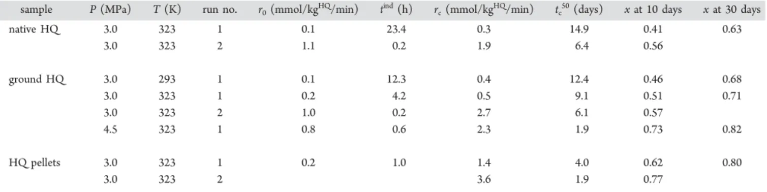
to the pressure level, which was 40 times lower in Allison and Barrer’s experiments. Finally, our conclusions agree with those Table 1. Kinetic Data of the Gas Captured by HQ Clathrate Formation Using Native, Powdered, and Compacted HQ: (r0)
Initial Reaction Rate, (rc) Maximum Reaction Rate, (tind) Induction Time, (tc50) Characteristic Time at Which the Clathrate
Occupancy (x) is 50%
sample P (MPa) T (K) run no. r0(mmol/kgHQ/min) tind(h) rc(mmol/kgHQ/min) tc50(days) x at 10 days x at 30 days
native HQ 3.0 323 1 0.1 23.4 0.3 14.9 0.41 0.63 3.0 323 2 1.1 0.2 1.9 6.4 0.56 ground HQ 3.0 293 1 0.1 12.3 0.4 12.4 0.46 0.68 3.0 323 1 0.2 4.2 0.5 9.1 0.51 0.71 3.0 323 2 1.0 0.2 2.7 6.1 0.57 4.5 323 1 0.8 0.6 2.3 1.9 0.73 0.82 HQ pellets 3.0 323 1 0.2 1.0 1.4 4.0 0.62 0.80 3.0 323 2 3.6 1.9 0.77
Figure 3.Molar quantity of gas captured by enclathration as a function of time using powdered HQ normalized by mass of HQ. Experiments with CO2at (green line) 293 K/3.0 MPa, (yellow line) 323 K/3.0
of Lee et al. (2011),22 who also found that the initial rate of formation of the HQ clathrates with pure CO2increases with
temperature. Consequently, in the conditions of this study, increasing pressure and temperature significantly enhanced the enclathration kinetics, as observed in typical gas−solid reactions.35−37An increase in pressure effectively concentrates
CO2molecules in the gas phase (and at the gas-solid interface)
and enhances the probability of contact between CO2and the
HQ surface. A temperature increase involves both a decrease of the density of the gas phase and the intensification of the degree of motion (i.e., thermal agitation) of the CO2molecules.
Therefore, the effect of pressure and temperature on kinetics of HQ clathrates formed by direct gas−solid reaction can be well explained by the collision theory.38
For the conditions investigated here, it appears that a 1.5 MPa increase in pressure has a more significant effect on the enclathration kinetics than a 30 K increase in temperature.
As described in literature,31 a linear fit generally links the
logarithm of the induction time to the induction pressure (i.e., overpressure by reference to the thermodynamic equilibrium pressure) for a constant temperature, as given byeq 1:
= · +
t a P b
ln(ind) ln( ind) (1)
where tind is the induction time expressed in hours, Pindis the
induction pressure expressed in MPa, and a and b are constants. Consequently, on the basis of our experimental data for powdered HQ at a temperature of 323 K (see Table 1), and considering a clathrate equilibrium pressure of 0.27 MPa at the said temperature,30the coefficients a and b were estimated at −4.4 and 5.9. It appeared that the induction time could be greatly reduced by increasing pressure. As an example, we were able to predict, based on these data, that the induction time would be about 5 min for a total pressure of 7.0 MPa at 323 K. To properly describe the kinetic law of enclathration when using powdered HQ, the induction time is deducted from the total time, as shown in Figure S3 of the Supporting Information. Drawing on the experimental data obtained with powdered HQ, the differential rate law was then used to determine the reaction order. From the linear plot of the reaction rate logarithm against the storage capacity logarithm (Figure S4of the Supporting Information), the slope was found to be equal to 1.98, confirming a second-order reaction, as already suggested in literature.31
Consequently, on the reduced time scale (after removal of the induction time), the reaction kinetics could be defined by
eq 2: = − X t k X d d [1 ] 2 (2)
where k is the rate constant and X the conversion ratio defined byeq 3:
=
X q
qeq (3)
where q is the storage capacity at time t, and qeqis the storage
capacity at an infinite time at which the equilibrium state is expected. Integrating eq 2 leads to eq 4, which gives the conversion ratio as a function of the reduced time:
= ′ + X kt 1 1 1 (4)
Considering the definition of the conversion ratio, it can be written aseq 5: = ′ + q q kt q 1 1 1 eq eq (5)
The latter can then be expressed aseq 6:
= ′ + q m t n 1 (6)
where m and n are respectively the slope and intercept of the linear fit of the storage capacity inverse as a function of the reduced time inverse. As shown inFigure S5of the Supporting Information, the linear fit of the storage capacity inverse as a function of the reduced time inverse produces both the equilibrium storage capacity and the rate constant at the pressure and temperature conditions considered. The clathrate occupancy at equilibrium state (xeq) is calculated based on
equilibrium storage capacities. All these data are presented in
Table 2.
Increasing both the temperature and pressure produced a higher rate constant. A 30 K increase doubled the rate constant and a 1.5 MPa increase quadrupled it. Furthermore, it was confirmed that the clathrate occupancies at equilibrium state were enhanced at low temperature30and high pressure.19
From the results obtained at a pressure of 3.0 MPa for powdered HQ, and considering the Arrhenius equation (see
Equations S1 to S3 in the Supporting Information), it was therefore possible to estimate that the activation energy of the CO2−HQ system was around 14 ± 1 kJ/molCO2. We are aware
that only two data points were used to estimate the activation energy and that the result given in this study is considered as a rough estimation. The only data that can be used for comparison is the activation energy of 17.6 kJ/molGuest found
for the Xenon-HQ system at about 0.1 MPa over a temperature range of around 218−267 K.31
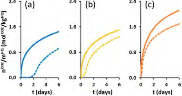
Effect of Conditioning and Recycling on Pure HQ. The native, powdered, and compacted forms of HQ were evaluated at 323 K and 3.0 MPa in two successive gas capture and gas release runs, performed on the same initial material. We have called cycle the combination of a formation step followed by a regeneration step: for example, cycle 1 is the first formation step followed by its regeneration step. Run 1 is therefore the stage in which HQ and gas react together for the first time, and run 2 (starting cycle 2) is the second formation step performed with the same material that has already undergone a gas capture and a gas release cycle (in cycle 1). These experiments allowed us to assess the influence that conditioning and recycling of the used reactive media has on kinetics and to study the variation of the induction time at this stage between the two runs. The first gas capture cycle lasted 1 month and the second 10 days.Figure 4
shows the amounts of CO2 captured over time in the two
successive gas capture runs for the three media used. In respect Table 2. Equilibrium Storage Capacity, Equilibrium Clathrate Occupancy, and Rate Constant Obtained Using Powdered HQ
P/T conditions qeq(molCO2/kgHQ) xeq k (min−1)
293 K/3.0 MPa 2.83 0.93 0.55 × 10⁻⁴
323 K/3.0 MPa 2.64 0.87 0.93 × 10⁻⁴
of the kinetic criteria obtained in Table 1, the clathrate formation kinetics were clearly improved by grinding and compacting the HQ crystals.
It also appeared that compaction is more efficient than grinding for improving kinetics (Figure 4b,c). We are, however, aware that an extra fine HQ power, even though hard to handle and difficult to use for practical and safety reasons, could compete with HQ pellets in terms of performance. For example, when HQ pellets are used instead of powdered HQ, the induction time is reduced by a factor of ∼4 and the enclathration kinetics are enhanced (e.g., tc50divided by ∼2 and rc multiplied by ∼2.6). These results clearly reveal the
importance of the contact area between the HQ and the gas: because of the high degree of fragmentation of the native crystals of HQ compacted in the pellet, this leads to numerous nucleation sites and a large surface area, which enhance both the clathrate initiation and formation processes. After one month’s reaction with CO2, clathrate occupancies of 0.63 ±
0.04, 0.71 ± 0.04, and 0.80 ± 0.05 at 323 K and 3.0 MPa for native, powdered, and compacted HQ were found. These differences in clathrate occupancy suggest that the systems have not all reached their equilibrium state (i.e., the equilibrium plateau where the mass of CO2captured does not evolve over
time) after 1 month. Note that the occupancy values found at
this pseudoequilibrium state are in good agreement with literature data.22,39−41
Looking at the second gas capture run, a marked improve-ment can be seen for the three media (i.e., a decrease in reaction times (tindand t
c50) and an increase in reaction rates (r0
and rc)) (seeFigure 4andTable 1). For example, comparing
the first and second gas capture runs for native HQ, the tc50was
divided by 2.3 and rc was multiplied by 5.9. Moreover, tind
appears to be considerably lower and was about 0.2 h for both native and powdered HQ. Interestingly enough, for the HQ pellets, no induction period can be observed. These improved kinetics in the second gas capture run are in line with the “pre-forming effect” recently highlighted by Coupan et al.17Indeed, it was demonstrated that after a first formation−dissociation cycle, there is a visible modification in the morphology of the crystal surfaces (the native HQ crystals have smooth, regular surfaces, and after one cycle, the same crystals exhibit a rough aspect with perforated surfaces), which results in a substantial increase in the solid−gas contact area.
Kinetic Evaluation of HQ−Silica Composite Materials. In this section, the gas capture experiments were conducted on the different HQ-based composites. The kinetic criteria obtained for these media are given in Table 3. As observed in our previous work,16 the HQ−silica composite materials make it possible to couple adsorption on silica and enclathration through HQ. Additional adsorption measure-ments have shown that the different native silica supports reach the adsorption plateau after 6 ± 3 min. Considering this period, the amount of gas captured by adsorption on the HQ−silica composite materials can be graphically estimated. The adsorption capacities (qADS) measured for the different media
are reported in Table 3. So, to study the effect of the impregnation and compare the results to those obtained with the other types of conditioning (i.e., grinding and compaction), the amount of CO2adsorbed on silica was deducted from the
total amount of CO2captured by the composite materials. For
this reason, only the amount of CO2captured by enclathration
is considered in the section below.
Compared to native HQ, and despite the fact that grinding and compaction of HQ seem kinetically interesting, it is obvious that the kinetics of CO2enclathration using HQ−silica
composite materials are much more efficient. Indeed, with these
Figure 4. Molar quantity of CO2 captured by enclathration as a
function of time at 323 K/3.0 MPa using (a) native HQ, (b) powdered HQ, and (c) compacted HQ normalized by mass of HQ. Dashed and solid lines represent the first and second gas capture runs, respectively.
Table 3. Kinetic Data of the CO2Captured by HQ Clathrate Formation Using HQ−Silica Composite Materials: (qTOT) Global
Gas Storage Capacity, (qADS) Adsorption Capacity, (r
c) Maximum Reaction Rate, (tc50) Characteristic Time at Which the
Clathrate Occupancy (x) is 50%
support τ(gHQ/gSupp.) P (MPa) T (K) run no. qTOT(mol/kgmedia) qADS(mol/kgmedia) r
c(mmol/kgHQ/min) tc50(h) x at 3 days
lp-SF 0.39 3.0 323 1 1.77 1.40 6.8 64.9 0.38 mp-SF 0.32 3.0 323 1 1.53 1.05 19.5 18.4 0.61 hp-SF 0.44 3.0 323 1 1.47 0.73 28.2 4.8 0.93 SS 0.10 3.0 323 1 0.52 0.31 1.8 16.6 0.81 0.27 3.0 323 1 0.80 0.29 5.6 8.4 0.80 0.41 1.5 298 1 0.78 0.26 2.5 92.9 0.57 0.41 1.5 323 1 0.75 0.18 2.6 64.9 0.56 0.41 1.5 348 1 0.63 0.14 2.6 51.4 0.56 0.41 3.0 323 1 1.02 0.28 22.7 4.5 0.81 0.41 3.0 323 2 0.90 0.28 12.1 17.8 0.71 0.41 3.0 323 3 0.97 0.28 11.1 14.4 0.75 0.41 3.0 323 4 1.00 0.28 21.8 13.9 0.79 0.41 4.5 323 1 1.15 0.35 35.8 1.9 0.99
media, the system reached an equilibrium value of clathrate occupancy after approximately 1 or 2 days, whereas 1 month’s reaction was insufficient to attain equilibrium state when using native, powdered, and compacted HQ. Moreover, it appeared that no induction period, or one of just a few minutes, was required when using HQ−silica composite materials. As an example, for the impregnated SS particles at 0.41 gHQ/gSupport, r
c
was increased by a factor of 71 and tc50 was decreased by a
factor of 79 compared to native HQ at 323 K and 3.0 MPa. As discussed in literature, the improved kinetics and much shorter induction period can be ascribed to the significant increase in contact area between the HQ and the gas due to the presence of HQ crystallites in the mesoporosity of the particle.16
Experiments with HQ−SS Composites. Using the SS-based composite materials with an HQ content of 0.41 ± 0.01 gHQ/
gSupport, we verified the effects of recycling, pressure and
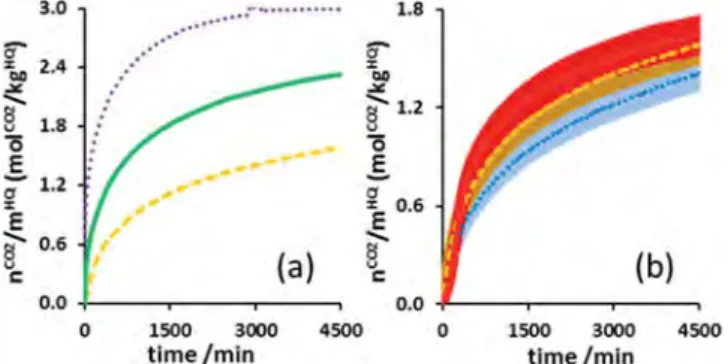
temperature.Figure 5 shows the amount of gas captured and
released by SS-based composite materials over time for four successive cycles. In contrast to the experiments with pure HQ, the first gas capture run with the composite materials appeared to be slightly faster than the following ones (seeFigure 5a). To explain this loss of efficiency in kinetics, we believe that the HQ starts to form a structure (i.e., the HQ crystallites agglomerate in the pores of the support) after the initial clathrate formation process, and this results in a slight decrease in the gas−solid contact area. Moreover, the first gas release phase was slower than the others (seeFigure 5b): around 9.8 h were needed to release all the captured CO2in the first release phase, and about
5.5 h were needed in the following ones. In this case, the release kinetics were improved after the first cycle. At the moment, we have no clear explanation as to why the global dissociation kinetics were enhanced after the first run, but we can nevertheless say that the trend is clearly reproducible. After both the first formation and dissociation runs, it is worth noting that the kinetics remained almost unchanged in the following runs. Consequently, the HQ-based composite materials can be recycled without any noticeable degradation to achieve reversible CO2capture.
Regarding the experiments performed at 323 K and 1.5, 3.0, and 4.5 MPa (Figure 6a), the previous section on pure HQ confirmed the favorable influence of pressure on kinetics. In the case of the composite material, however, the improvement was less pronounced than for powdered HQ. It is worth noting that
in the actual case study, the test at 323 K and 4.5 MPa using the SS-based composite material with an HQ content of 0.41 ± 0.01 gHQ/gSupportgave the best kinetic criteria (i.e., r
c of 35.8
mmolCO2/kgHQ/min, and t
c50 of 1.9 h) and a clathrate
occupancy of 0.99.
Concerning the experiments performed at 1.5 MPa and 298, 323, and 348 K (Figure 6b), we observed first of all that the curves are very close. In addition, for the experiments at 348 and 323 K, the curve profiles indicated a slight phenomenon of gas sorption corresponding to gas solubilization in the α-HQ. r0
was therefore measured at 1.0 and 2.2 mmolCO2/kgHQ/min.
Because of the superposition of adsorption phenomena at the beginning of the cycle, it is sometimes hard to precisely evaluate the induction times. At 1.5 MPa, the induction time was less than 15 min for the three temperatures tested. As for the influence of temperature on the enclathration kinetics when using the HQ-based composite, the trend did not appear clearly on the plots of Figure 6b as error bars are superimposed on some parts of the curves. However, comparison of the t50values
presented in Table 3 show a clear global trend which is consistent with the one given for pure HQ: the enclathration kinetics are improved by a temperature increase. For example,
t50 equals 92.9, 64.9, and 51.4 h at 298, 323, and 348 K,
respectively. In addition, with reference to the experiment performed at 323 K and 1.5 MPa, it is obvious that a pressure increase of 1.5 MPa is preferable to a temperature increase of 25 K for improving global kinetics.
On the basis of the kinetic law (eq 5) given in the previous section for powdered HQ, calculations were performed for the HQ-based composite synthesized from SS particles to determine rate constants and gas storage capacities at equilibrium. Table 4 presents the results obtained and shows that the rate constants varied with the pressure and temperature conditions in the same way as discussed previously. Besides, the rate constants obtained with the HQ-based composite were generally higher than those calculated when using powdered HQ. It is worth noting, however, that the rate constant for HQ powder at 323 K and 4.5 MPa was slightly higher than that of the composite at 298 K and 1.5 MPa. From the results obtained at a pressure of 1.5 MPa for the HQ-based composite, it was then possible to calculate the activation energy of the CO2−
HQ clathrate formation reaction (using Equation S2 in the
Figure 5.Molar quantity of CO2(a) captured by enclathration as a
function of time at 323 K/3.0 MPa and (b) released at 348 K/0.1 kPa using SS particles impregnated at 0.41 gHQ/gSupport, normalized by
mass of HQ: (solid line) run 1, (dotted line) run 2, (dashed line) run 3, and (dotted/dashed line) run 4.
Figure 6.Molar quantity of gas captured by enclathration as a function of time using SS particles impregnated at 0.41 gHQ/gSupportnormalized
by mass of HQ. (a) Experiments performed at 323 K at different pressures: (dashed line) 1.5 MPa, (solid line) 3.0 MPa, and (dotted line) 4.5 MPa. (b) Experiments performed at 1.5 MPa at different temperatures: (dotted line) 298 K, (dashed line) 323 K, and (solid line) 348 K. The error bars on the data points correspond to a relative uncertainty of 7%.
Supporting Information), estimated at around 18 ± 2 kJ/ molCO2.
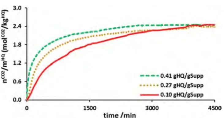
Influence of the Precursor Content and the Silica Support. To better understand the rate at which the HQ-based composite materials capture the CO2, experiments were
performed on composites with different HQ contents (SS particles impregnated at 0.41, 0.27, and 0.10 gHQ/gSupport) and
formed from supports with different pore sizes (h-SF, m-SF, l-SF, and SS particles).Figures 7and8show the amount of gas captured by these different HQ-based composite materials over time.
Looking atFigure 7, it appears that the kinetics depend on the HQ content of the composite. Indeed, the kinetics of the composite with a high HQ content were faster. The rcwere 1.8,
5.6, and 22.7 mmolCO2/kgHQ/min for HQ contents of 0.10,
0.21, and 0.41 gHQ/gSupport. These observations suggest that the
pores contain more small HQ crystallites, the greater the HQ content of the composite materials. The developed area of the impregnated HQ is therefore larger for high HQ contents.
Looking at the CO2capture results presented inFigure 8, we
can see that the kinetics were affected when HQ-based composite materials synthesized from different silica supports (i.e., impregnated lp-SF, mp-SF, hp-SF, and SS particles) were used. The differences between these composites mainly concerned pore size and specific area (Table S1 of the Supporting Information). Compared to Figure 7, we can assume here that the different precursor contents of the tested media (i.e., from 0.32 to 0.44 gHQ/gSupport) are not significant
enough to explain the major differences observed between the kinetic profiles shown in Figure 8. The results highlight an improvement in kinetics when both the pore size increased and the specific area decreased (e.g., the rc of impregnated lp-SF,
mp-SF, and hp-SF particles were measured at 6.8, 19.5, and 28.2 mmolCO2/kgHQ/min, respectively). In addition, the
clathrate occupancies of impregnated lp-SF, mp-SF, and hp-SF particles were measured at 0.38, 0.61, and 0.93, respectively, after 2 days’ reaction (Table 3). We can therefore conclude that the smaller the pore diameter (within the range of those tested in this study), the lower the kinetic efficiency. This conclusion might imply that (i) the HQ impregnated in small pores (such as those present in lp-SF and mp-SF) does not react with the gas because the pores are plugged, or (ii) the amount of HQ in the pores is very low (or the pores contain no HQ), and the kinetic measurements are related to the HQ crystals at the particle surface explaining the very low values of occupancy obtained after 2 days’ reaction. All these points are consistent with our previous conclusions drawn in theConditioning and Characterizationsection: the PSD suggests that the pores of lp-SF and mp-lp-SF are totally filled or plugged with HQ crystals. When comparing impregnated hp-SF and SS particles, there are no substantial kinetic dissimilarities. We can thus infer that both the size of the HQ crystallites in the pores and the developed area of the impregnated HQ are of the same order of magnitude for composites synthesized from both hp-SF and SS particles. On the basis of these experiments, it appears that the minimum pore size of the silica supports must be greater than 16 nm (i.e., pore size of native mp-SF) to ensure the efficiency of the enclathration process when using HQ-based composite materials.
■
CONCLUSIONSThis study highlights the influence of the reactive medium and of pressure and temperature conditions on the kinetics of HQ clathrate formation by direct gas−solid reaction.
When using powdered HQ, it was demonstrated that high temperature, and more particularly high pressure, enhanced kinetics. Comparison of the results obtained in the CO2capture
experiments using pure HQ in three forms (native, powdered, and compacted) as the reactive medium revealed that the enclathration kinetics can be improved by conditioning the HQ which increases the gas−solid contact area. Indeed, HQ pellets are more efficient than HQ powder, with a particle size of 25 μm, and native HQ. Our experimental results therefore demonstrated the important effect of textural parameters on kinetics. In addition, the preforming effect of HQ was confirmed after a first gas capture run, as significant improvements could be observed for native, powdered, and compacted HQ in the second gas capture run. This observation proved that HQ could be recycled to perform successive gas Table 4. Equilibrium Storage Capacities, Equilibrium
Clathrate Occupancies and Rate Constants Obtained Using the HQ-Based Composite Impregnated at 0.41 gHQ/gSupport
for the First Gas Capture Run
P/T conditions qeq(molCO2/kgHQ) xeq k (min−1)
298 K/1.5 MPa 2.53 0.83 3.31 × 10⁻⁴
323 K/1.5 MPa 2.26 0.75 6.12 × 10⁻⁴
348 K/1.5 MPa 2.06 0.68 9.20 × 10⁻⁴
323 K/3.0 MPa 2.51 0.83 53.45 × 10⁻⁴
323 K/4.5 MPa 3.03 1.0 60.00 × 10⁻⁴
Figure 7.Molar quantity of gas captured by enclathration as a function of time at 323 K/3.0 MPa using impregnated SS particles, normalized by mass of HQ. Precursor content of (dashed line) 0.41 gHQ/gSupport,
(dotted line) 0.27 gHQ/gSupport, and (solid line) 0.10 gHQ/gSupport.
Figure 8.Molar quantity of gas captured by enclathration as a function of time at 323 K/3.0 MPa using (dotted/dashed line) h-SF, (dotted line) m-SF, (solid line) l-SF particles, and (dashed line) SS particles impregnated at 0.41 gHQ/gSupportnormalized by mass of HQ.
capture runs. In addition, in the specific case of the HQ pellets, there was no induction time as from the second gas capture run.
Owing to these experimental measurements, we proved that the enclathration of CO2by HQ is a second-order reaction. For
the different P/T conditions, both the rate constants and clathrate occupancies at equilibrium state were determined. In the specific case of HQ powder at a pressure of 3.0 MPa and within a temperature range of 293−323 K, the activation energy of the CO2−HQ clathrate formation reaction was estimated to be around 14 ± 1 kJ/molCO2.
The HQ−silica composite materials used as a reactive medium gave the best results in terms of improving the HQ clathrate formation kinetics. Indeed, when HQ−silica compo-site materials are used, the induction period can be almost done away with and the enclathration rate increases substantially compared with the other reactive media. At 323 K and 3.0 MPa, the use of an HQ-based composite formed with SiliaSphère particles increased the enclathration rate by a factor of 71 and reduced the time needed to fill 50% of the clathrate cavities by a factor of 79 in contrast to pure native HQ. Moreover, for a test performed at 323 K and 4.5 MPa with the same composite material, the time needed to fill 50% of the clathrate cavities was reduced to 1.9 h and a clathrate occupancy of 0.99 was achieved. In view of the trends given in this study, these kinetic factors could be even higher when working at higher pressure. In addition, the HQ−silica composite materials can be recycled to achieve reversible CO2capture. However, to obtain efficient
HQ-based composites, it is required (i) to have a support with a suitable pore size (>16 nm) to avoid plugging all the particle pores and (ii) to perform the impregnation process with a high concentrated HQ solution. These two points ensure that the pores of the support contain small HQ crystallites permitting a large developed HQ reactive area.
Now, work is in progress to evaluate the viability and feasibility of using this type of reactive medium at pilot scale in clathrate-based gas separation processes.
■
ASSOCIATED CONTENT*
S Supporting InformationThe Supporting Information is available free of charge on the
ACS Publications websiteat DOI:10.1021/acs.iecr.8b01462. Aspect of native and powdered HQ; physicochemical characterizations; kinetic calculations; Arrhenius equa-tion (PDF)
■
AUTHOR INFORMATIONCorresponding Author
*Phone: +335 40 17 51 09. E-mail: [email protected].
ORCID
Jean-Philippe Torré:
0000-0001-5735-8626Christophe Dicharry:
0000-0002-6318-3989Author Contributions
The manuscript was written through contributions of all authors. All authors have given approval to the final version of the manuscript.
Notes
The authors declare no competing financial interest.
■
ACKNOWLEDGMENTSWe acknowledge the entire work group involved in the ORCHIDS project, as well as the Gas Solutions department of Total SA (E&P Division) and the Carnot Institute ISIFoR (Institute for the Sustainable Engineering of Fossil Resources) for their financial support. We thank Total for providing UMS 3360 DMEX with the Zeiss Xradia Versa 510T used to carry out the tomographic acquisitions described in this article; we also extend our warmest thanks to F. Guerton, P. Senechal, and P. Moonen for performing the tomographic scans and analyzing them.
■
ABBREVIATIONS USED HQ = hydroquinone DI = dry impregnation WI = wet impregnation■
REFERENCES(1) Nema, P.; Nema, S.; Roy, P. An Overview of Global Climate Changing in Current Scenario and Mitigation Action. Renewable
Sustainable Energy Rev. 2012, 16, 2329−2336.
(2) Míguez, J. L.; Porteiro, J.; Pérez-Orozco, R.; Patiño, D.; Rodríguez, S. Evolution of CO2 Capture Technology Between 2007
and 2017 Through the Study of Patent Activity. Appl. Energy 2018,
211, 1282−1296.
(3) Dashti, H.; Zhehao Yew, L.; Lou, X. Recent Advances in Gas Hydrate-Based CO2Capture. J. Nat. Gas Sci. Eng. 2015, 23, 195−207.
(4) Tajima, H.; Yamasaki, A.; Kiyono, F. Energy Consumption Estimation for Greenhouse Gas Separation Processes by Clathrate Hydrate Formation. Energy 2004, 29, 1713−1729.
(5) Linga, P.; Kumar, R.; Englezos, P. The Clathrate Hydrate Process for Post and Pre-Combustion Capture of Carbon Dioxide. J. Hazard.
Mater. 2007, 149, 625−629.
(6) Duc, N. H.; Chauvy, F.; Herri, J.-M. CO2Capture by Hydrate
Crystallization - A Potential Solution for Gas Emission of Steelmaking Industry. Energy Convers. Manage. 2007, 48, 1313−1322.
(7) Castellani, B.; Rossi, F.; Filipponi, M.; Nicolini, A. Hydrate-Based Removal of Carbon Dioxide and Hydrogen Sulphide from Biogas Mixtures: Experimental Investigation and Energy Evaluations. Biomass
Bioenergy 2014, 70, 330−338.
(8) Dabrowski, N.; Windmeier, C.; Oellrich, L. R. Purification of Natural Gases with High CO2Content Using Gas Hydrates. Energy
Fuels 2009, 23, 5603−5610.
(9) Ricaurte, M.; Dicharry, C.; Broseta, D.; Renaud, X.; Torre, J.-P. CO2 Removal from a CO2-CH4 Gas Mixture by Clathrate Hydrate
Formation using THF and SDS as Water-Soluble Hydrate Promoters.
Ind. Eng. Chem. Res. 2013, 52, 899−910.
(10) Ricaurte, M.; Dicharry, C.; Renaud, X.; Torre, J.-P. Combination of Surfactants and Organic Compounds for Boosting CO2Separation
from Natural Gas by Clathrate Hydrate Formation. Fuel 2014, 122, 206−217.
(11) Babu, P.; Linga, P.; Kumar, R.; Englezos, P. A Review of the Hydrate Based Gas Separation (HBGS) Process for Carbon Dioxide Precombustion Capture. Energy 2015, 85, 261−279.
(12) Linga, P.; Clarke, M. A. A Review of Reactor Designs and Materials Employed for Increasing the Rate of Gas Hydrate Formation. Energy Fuels 2017, 31, 1−13.
(13) Atwood, J. L.; Steed, J. W. Encyclopedia of Supramolecular
Chemistry; CRC Press, Taylor & Francis Group: Boca Raton, FL,
2004; Vol. 1.
(14) Steed, J. W.; Turner, D. R.; Wallace, K. J. Core Concepts in
Supramolecular Chemistry and Nanochemistry; John Wiley & Sons:
Chichester, England, 2007.
(15) Atwood, J. L.; Davies, J. E. D.; MacNicol, D. D. Inclusion
Compounds, Vol. 2: Structural Aspects of Inclusion Compounds Formed by Organic Host Lattices; Academic Press Inc.: London ltd, 1984.
(16) Coupan, R.; Plantier, F.; Torré, J.-P.; Dicharry, C.; Sénéchal, P.; Guerton, F.; Moonen, P.; Khoukh, A.; Kessas, S. A.; Hemati, M. Creating Innovative Composite Materials to Enhance the Kinetics of CO2Capture by Hydroquinone Clathrates. Chem. Eng. J. 2017, 325,
35−48.
(17) Coupan, R.; Péré, E.; Dicharry, C.; Torré, J.-P. New Insights on Gas Hydroquinone Clathrates using in Situ Raman Spectroscopy: Formation/Dissociation Mechanisms, Kinetics and Capture Selectiv-ity. J. Phys. Chem. A 2017, 121, 5450−5458.
(18) Belosludov, V. R.; Dyadin, Y. A.; Chekhova, G. N.; Kolesov, B.; Fadeev, S. I. Hydroquinone Clathrates and the Theory of Clathrate Formation. J. Inclusion Phenom. 1985, 3, 243−260.
(19) Conde, M. M.; Torré, J.-P.; Miqueu, C. Revisiting the Thermodynamic Modelling of Type I Gas-Hydroquinone Clathrates.
Phys. Chem. Chem. Phys. 2016, 18, 10018−10027.
(20) Lee, Y.-J.; Han, K. W.; Jang, J. S.; Jeon, T.-I.; Park, J.; Kawamura, T.; Yamamoto, Y.; Sugahara, T.; Vogt, T.; Lee, J.-W.; et al. Selective CO2 Trapping in Guest-Free Hydroquinone Clathrate Prepared by
Gas Phase Synthesis. ChemPhysChem 2011, 12, 1056−1059. (21) Lee, J.-W.; Poudel, J.; Cha, M.; Yoon, S. J.; Yoon, J.-H. Highly Selective CO2Extraction from a Mixture of CO2and H2Gases Using
Hydroquinone Clathrates. Energy Fuels 2016, 30, 7604−7609. (22) Lee, J.-W.; Yoon, J.-H. Preferential Occupation of CO2
Molecules in Hydroquinone Clathrates Formed from CO2/N2 Gas
Mixtures. J. Phys. Chem. C 2011, 115, 22647−22651.
(23) Lee, J.-W.; Dotel, P.; Park, J.; Yoon, J.-H. Separation of CO2
from Flue Gases using Hydroquinone Clathrate Compounds. Korean J.
Chem. Eng. 2015, 32, 2507−2511.
(24) Coupan, R.; Dicharry, C.; Torré, J.-P. Hydroquinone Clathrate Based Gas Separation (HCBGS): Application to the CO2/CH4Gas
Mixture. Fuel 2018, 226, 137−147.
(25) Coupan, R.; Chabod, M.; Dicharry, C.; Diaz, J.; Miqueu, C.; Torré, J.-P. Experimental Determination of Phase Equilibria and Occupancies for CO2, CH4, and N2Hydroquinone Clathrates. J. Chem.
Eng. Data 2016, 61,2565−2572.
(26) Belmabkhout, Y.; Sayari, A. Adsorption of CO2from Dry Gases
on MCM-41 Silica at Ambient Temperature and High Pressure. 2: Adsorption of CO2/N2, CO2/CH4 and CO2/H2 Binary Mixtures.
Chem. Eng. Sci. 2009, 64, 3729−3735.
(27) Cavenati, S.; Grande, C. A.; Rodrigues, A. E. Adsorption Equilibrium of Methane, Carbon Dioxide, and Nitrogen on Zeolite 13X at High Pressures. J. Chem. Eng. Data 2004, 49, 1095−1101.
(28) Banerjee, R.; Phan, A.; Wang, B.; Knobler, C.; Furukawa, H.; O’Keeffe, M.; Yaghi, O. M. High-Throughput Synthesis of Zeolitic Imidazolate Frameworks and Application to CO2 Capture. Science
2008, 319, 939−943.
(29) Himeno, S.; Komatsu, T.; Fujita, S. High-Pressure Adsorption Equilibria of Methane and Carbon Dioxide on Several Activated Carbons. J. Chem. Eng. Data 2005, 50, 369−376.
(30) Uchida, T.; Hondoh, T.; Mae, S.; Kawabata, J. Physical Data of CO2Hydrates. In Direct Ocean Disposal of carbon Dioxide; Handa, N.,
Ohsumi, T., Eds.;Terra Scientific Publishing Company: Tokyo, 1995. (31) Allison, S. A.; Barrer, R. M. Clathration by Phenol and Quinol. Part.II Kinetics. Trans. Faraday Soc. 1968, 64, 557−565.
(32) Lee, J.-W.; Lee, Y.; Takeya, S.; Kawamura, T.; Yamamoto, Y.; Lee, Y.-J.; Yoon, J.-H. Gas-Phase Synthesis and Characterization of CH4-Loaded Hydroquinone Clathrates. J. Phys. Chem. B 2010, 114,
3254−3258.
(33) Li, X.; Yin, Q.; Chen, W.; Wang, J. Solubility of Hydroquinone in Different Solvents from 276.65 to 345.10 K. J. Chem. Eng. Data 2006, 51, 127−129.
(34) Khaddour, F.; Knorst-Fouran, A.; Plantier, F.; Piñeiro, M. M.; Mendiboure, B.; Miqueu, C. A Fully Consistent Experimental and Molecular Simulation Study of Methane Adsorption on Activated Carbon. Adsorption 2014, 20, 649−656.
(35) Baasel, W. D.; Stevens, W. F. Kinetics of a Typical Gas-Solid Reaction. Ind. Eng. Chem. 1961, 53, 485−488.
(36) Slycke, J. T.; Mittemeijer, E. J.; Somers, M. A. J. Thermochemical
Surface Engineering of Steels; Mittemeijer, E. J., Somers, M. A. J., Eds.;
Woodhead Publishing, Elesevier Ltd., Cambridge, UK, 2015; Vol. 1, pp 3−111.
(37) Szekely, J.; Evans, J. W.; Sohn, H. Y. Gas−Solid Reactions.; Academic Press Inc.: New York, 1976.
(38) Balint-Kurti, G. G.; Pavlov, A. P. Theory of Molecular Collisions; RSC Theoretical and Computational Chemistry Series No. 7; Royal Society of Chemistry: Cambridge, U.K, 2015.
(39) Torré, J.-P.; Coupan, R.; Chabod, M.; Péré, E.; Labat, S.; Khoukh, A.; Brown, R.; Sotiropoulos, J.-M.; Gornitzka, H. CO2− Hydroquinone Clathrate: Synthesis, Purification, Characterization and Crystal Structure. Cryst. Growth Des. 2016, 16, 5330−5338.
(40) Peyronel, G.; Barbieri, G. On some new clathrates of hydroquinone. J. Inorg. Nucl. Chem. 1958, 8, 582−585.
(41) McAdie, H. G. Thermal Decomposition of Molecular Complexes: IV. Further Studies of the β-Quinol Clathrates. Can. J.