Cellular expression through morphogen
delivery by light activated magnetic microrobots
The MIT Faculty has made this article openly available.
Please share
how this access benefits you. Your story matters.
Citation
Das, Sambeeta et al. "Cellular expression through morphogen
delivery by light activated magnetic microrobots." Journal of
Micro-Bio Robotics 15, 2 (June 2019): 79–90 © 2019 Springer-Verlag
As Published
http://dx.doi.org/10.1007/s12213-019-00119-x
Publisher
Springer Science and Business Media
Version
Author's final manuscript
Citable link
https://hdl.handle.net/1721.1/128381
Terms of Use
Creative Commons Attribution-Noncommercial-Share Alike
Cellular Expression through Morphogen Delivery by Light
Acti-vated Magnetic Microrobots
Cite this article as:
Sambeeta Das, Elizabeth E. Hunter, Nicholas A. DeLateur,
Ed-ward B. Steager, Ron Weiss and Vijay Kumar, Cellular Expression through Morphogen
Delivery by Light Activated Magnetic Microrobots, Journal of Micro-Bio Robotics
doi:
10.1007/s12213-019-00119-x
This Author Accepted Manuscript is a PDF file of a an unedited peer-reviewed manuscript that
has been accepted for publication but has not been copyedited or corrected. The official version
of record that is published in the journal is kept up to date and so may therefore differ from this
version.
Terms of use and reuse: academic research for non-commercial purposes, see here for full
terms.
http://www.springer.com/gb/open-access/authors-rights/aam-terms-v1
Cellular Expression Through Morphogen Delivery by Light
Activated Magnetic Microrobots
June 4, 2019
Sambeeta Das∗1, Elizabeth E. Hunter2, Nicholas A. DeLateur3, Edward B. Steager2, Ron
Weiss4 and Vijay Kumar2
1Department of Chemical and Biomolecular Engineering, University of Pennsylvania,
Philadel-phia, USA
2GRASP Laboratory, School of Engineering and Applied Science, University of Pennsylvania,
Philadelphia, USA
3Department of Chemistry, Massachusetts Institute of Technology, Cambridge, USA
4Department of Biological Engineering, Massachusetts Institute of Technology, Cambridge, USA
∗Corresponding author
*We gratefully acknowledge the support of ONR grant N00014-11-1-0725, NSF grant CNS-1446474 and NSF grant CNS-1446592. E.E.H. was supported by NSF Graduate Research Fellow-ship grant DGE-1845298
Abstract
Microrobots have many potential uses in microbiology since they can be remotely actuated and precisely manipulated in biochemical fluids. Cellular function and response depends on biochemicals. Therefore, various delivery methods have been developed for delivering biologi-cally relevant cargo using microrobots. However, localized targeting without payload leakage during transport is challenging. Here, we design a microrobotic platform capable of on-demand delivery of signaling molecules in biological systems. The on-demand delivery method is based on a light-responsive photolabile linker which releases a cell-to-cell signaling molecule when exposed to light, integrated on the surface of microrobots. Successful delivery of the signal-ing molecules and subsequent gene regulation is also demonstrated. This proposed method can be used for multiple applications, especially in biology, engineering, and medicine where on-demand delivery of chemical cargo at targeted locations is important.
1
INTRODUCTION
Microrobots, especially magnetically driven microrobots, have been an exponentially growing area of research due to their potential applications in various fields such as drug delivery and synthetic biology[1]. Magnetic robots offer unique advantages for biomedical applications since they can be steered in biological samples without harming cells or tissues[2]. Some applications of magnetic mi-crorobots which have been investigated are transport and targeted delivery of cargo, manipulation of cells, and generation of 3D structures[3, 4, 5]. One interesting application that we investigate in this work is interfacing magnetic microrobots with synthetically engineered cells to implement user-defined control, sensing, and communication strategies. The range of cellular processes that drive cell communication and function depend on gradients of small molecules called signaling molecules[6]. Most of these gradients are formed through diffusion of the signaling molecule from a localized source and can be described by a reaction diffusion equation. This work will focus on developing a proof-of-concept microrobotic platform capable of delivering signaling molecules to cells. To design a system capable of communication, sensing, and control within a cellular network, we develop a route of photochemically delivering signaling molecules to bacterial cells using cylin-drical microrobots. We choose a strain of synthetically engineered Escherichia coli for our system. One of the signaling molecules of interest to this quorum sensing E. coli is N-butyryl-homoserine lactone (C4HSL). For our proof-of-concept experiments we design a generic photocleavable linker
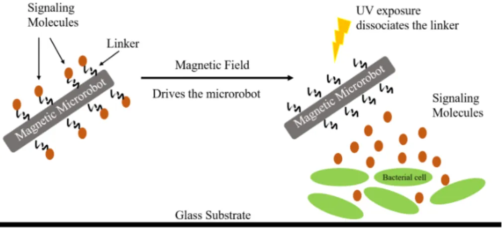
Figure 1: Schematic representation of the light-controlled targeted delivery system. Signaling molecules are attached to a magnetically actuated microrobot using a photocleavable linker. The microrobot drives towards the desired cell culture. Then, it is exposed to UV light to cleave the linker and release the signaling molecules which diffuse into the engineered bacterial cells. The cells respond to the signaling molecule by expressing genes to produce fluorescent proteins.
system, optimize it for C4HSL and attach the molecule to the microrobots. On exposure to low-intensity UV light, the photocleavable linker dissociates, thus exposing the bacterial cells to the signaling molecules, inducing protein expression in the cells.
1
2
MOTIVATION
Current methods of cargo delivery in literature suffer from many disadvantages, especially for ap-plication in biological systems. Most delivery systems are designed around a particular payload type[8] and the functionality of the microrobot is tuned to the properties of the therapeutic chem-ical. This leads to relatively limited adaptability of the carrier to different payload types. Passive methods of cargo delivery are also quite leaky, with payload leakage only controlled by the degra-dation or porosity of the microrobot matrix. Therefore, to overcome low distribution efficiencies, most carrier systems incorporate high concentrations of the bioactive molecule, resulting in lethal systemic toxicities[9]. One of the methods of overcoming this challenge is developing controlled on-site release schemes. There are two important considerations for such schemes. The cargo carrier should be general and easily adaptable to molecules of interest such as drugs, nucleic acids, proteins, or peptides. Secondly, the navigation and cargo release mechanism should be biocom-patible. To this effect, we choose a combination of magnetic actuation for control and light for release to design a mobile microrobot with controlled delivery of cargo (Fig. 1). Magnetic actua-tion is highly selective and magnetic fields can be applied without perturbing biological fluids[10]. For precise spatio-temporal control over payload release, light is an excellent choice. Light can be used remotely without changing the local environment of the cells and can be tuned in terms of irradiation time, wavelength and intensity[11, 12]. In our light activated delivery system, the active chemical or payload, namely the signaling molecule, is caged or inactive on the surface of the microrobot. The chemical payload can only become active or diffuse into the cells on exposure to light. This represents a key advantage of our delivery system over traditional methods, hav-ing essentially a ‘trigger’ for diffusion. In traditional delivery methods[13], the active chemical or payload can diffuse uncontrollably from the microrobot, in the process of driving it to the target location. However, in our system, the payload is first localized and can only be accessed when the microrobot is light-activated.
Cell-to-cell communication in many gram-negative bacterial species is governed by the diffusion
1This paper is an invited extended version of [7] from the MARSS conference. The synthesis of the photocleavable
linker, integration of the cylindrical microrobots with the linker, and protein expression in bacterial cells are the same as that paper, while we have added further data on the dose response of the signaling molecule in the cells. We have also demonstrated cellular response using directed microrobots and extended the microrobot type to helical microrobots, which will be used for further extension of the work in the future.
Figure 2: (a) Schematic representation of the microcylinders. The microcylinders were fabricated from SU-8 polymer and coated with a bilayer of Ni (55nm) followed by Titanium dioxide (15 nm). (b) Brightfield image of the microrobots on an agar surface with the bacterial cell culture in the agar, at 15X magnification.
of small molecules. Quorum sensing bacteria release signaling molecules whose concentration in the system alters gene expression[14]. One of the most common quorum sensing mechanisms in bacterial cells is the Rhll/RhlR systems, with the corresponding signaling molecule as N-butyryl-homoserine lactone. There are numerous other quorum sensing mechanisms in bacterial cells with each responding to different chemical signals. Gene expression in such cells is dependent on the diffusion of the small molecules[14]. This presents some significant challenges in adapting current microrobot delivery methods to engineered bacterial cell systems. Many microrobotic carriers comprise of robots which encapsulate small molecules such as drugs or nucleic acids and release their payload via diffusion of the small molecule from the robot[13, 15, 16]. However, since the gene expression in bacterial quorum sensing depends on the concentration of signaling molecule, diffusion of the payload from the microrobot would lead to homogenization of the chemical concentration gradient, leading to the loss of any spatial or temporal behavior.
3
Material and Methods
3.1
Fabrication of microrobots
The robotic platform is composed of microcylinders coated with Nickel/Titanium dioxide. The microrobots were fabricated using commercially obtained photopolymer SU-8-5 (MicroChem). 1 mL of Omnicoat (MicroChem) was spincoated on a 4-inch silicon wafer (cleaned with Piranha Etch) at 3000 rpm for 30 sec. The substrate was baked at 200 degrees celsius for 1 min. Then 4 mL of Su-8-5 was spin coated on the silicon substrate for 30 sec at 3000 rpm. It was baked at 65◦C for 2 min and 95◦C or 5 min. Subsequently, the substrate was exposed to the lithography mask at 365 nm using SUSS MicroTec MA-6 (University of Pennsylvania Nanofabrication Facility). After exposure the substrate was again baked at 65◦C for 1 min and 95◦C for 2 min. After post-bake exposure, the substrate was developed in SU-8 developer (MicroChem) for 2 min, and the structures imaged under microscope. The cylinders were 10 µm in length and 5 µm in diameter. The surface of the microcylinders was coated on three sides with a Ni/TiO2bilayer, making them magnetic. A 55 nm
thick layer of Nickel (>99.9% Sigma Aldrich) followed by 15 nm of Titanium dioxide was evaporated onto the microcylinders under vacuum in a Lesker PVD75 electron beam evaporator and DC/RF Sputterer (Nanofabrication lab, University of Pennsylvania). The microcylinders were retrieved from the substrate using the dull edge of a blade and suspended in DI water. The schematic representation of the microrobots is shown in Fig. 2. The Ni enables us to control the cylinders using low magnetic field gradients (50 mT/m) and the TiO2layer prevents the oxidation of the Ni
layer[17, 13]. It also improves the binding of the linker to the microrobot surface (Fig. 2(a)).
3.2
Magnetic Setup
The microrobots were actuated using magnetic fields which were generated using two different methods. The first method was using a permanent magnet. The second method was using four in-plane electromagnetic coils. Details about the magnetic setup can be found in previously published work[18, 19].
3.3
Bacterial plasmids and strains
Two different strains of genetically modified E. coli were used in this work. NEB 10-beta E. coli cells were transformed either with a plasmid pNDW1 which promotes the constitutive expression
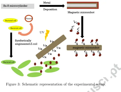
Figure 3: Schematic representation of the experimental setup.
of Green Fluorescent Protein (GFP) or a plasmid pNDW2 which expresses GFP in the presence of N-butyryl-L-Homoserine lactone (C4HSL, Cayman Chemical, 10007898). Plasmids were assembled by goldengate cloning using empty vectors as described in The MoClo Toolkit[20], which was a gift from Sylvestre Marillonnet (Addgene kit number 1000000044). Both pNDW1 and pNDW2 are Kanamycin resistant with pBR322 origin. pNDW1 utilizes pLacIq strong constitutive promoter driving GFP expression. pNDW2 utilizes pRhl-tetO from[21] driving GFP expression. Cells were grown overnight at 37◦C and 200 RPM in Luria-Bertani (LB) broth, then back diluted 1:100 into fresh M9 minimal media, and grown to an optical density at 600 nm of approximately 0.3 prior to induction. All growth media was supplemented with 10 µg/mL of kanamycin selection antibiotic. The experimental setup is outlined in Fig. 3.
3.4
Signaling molecule with photocleavable linker
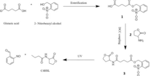
One of the most common photolabile protecting group in chemistry is the o-nitro benzyl group [22]. We designed an o-nitro benzyl based photocleavable linker starting from commonly available reagents and using standard organic reactions. Figure 4 outlines the synthesis steps. Benzyl alcohol was treated with excess amounts of Glutaric acid to give their corresponding ester 1[23]. After pu-rifcation, nitration of ester 1 was done using a mixture of concentrated nitric acid and sulfuric acid in an ice bath to generate the corresponding o- and p-substituted nitrobenzyl analogues[24]. After separation, the o-nitro product 2 is coupled to L-homoserine lactone (C4HSL; signaling molecule) using DCC coupling[25] to give the photocleavable linker 3. On exposure to UV light, the linker dissociates to generate C4HSL, carbon dioxide and 2-nitrosobenzaldehyde[22]. The successful syn-thesis of the linker was characterized by NMR:1H NMR (400 MHz, CDCl
3) δ 8.09 (d, 1H), δ 7.74
(dd, 1H), δ 7.54 (m, 2H), δ 5.15 (s, 2H), δ 4.56 (m, 2H), δ 4.29 (dd, 1H), δ 2.24 (t, 6H), δ 1.69 (m, 2H). After synthesis, 100 mM of the linker was incubated overnight with 2% w/v of the microcylin-ders. The linker is adsorbed on the microcylinder surface, leading to a microrobotic system with a photolabile payload. The microrobots are then washed by centrifugation and resuspended in pure DMSO. The chemical vapor deposition techniques used in our experiments lead to the formation of rutile TiO2thin films[26]. Previous research has suggested that organic molecules especially those
containing surface hydroxyl groups are chemiadsorbed irreversibly on the surface of TiO2[27, 28].
The cited works also discuss the properties and adsorption mechanism of the chemical layer on the TiO2surface. Nagao et.al. also outline the adsorption isotherms of organic molecules on rutile
surfaces over a range of temperatures. Thus, we expect the photochemical linker to be irreversibly adsorbed on the microrobot surface.
Figure 4: Glutaric acid and Benzyl alcohol are reacted to give their corresponding ester 1. Nitration of ester 1 is done using nitric acid and sulfuric acid to generate o- and p-substituted nitrobenzyl products. After purification, the o-nitro product 2 is coupled to L-Homoserine lactone using DCC coupling to give the photocleavable linker 3. On exposure to UV light, the linker dissociates to generate C4HSL, carbon dioxide and 2-nitrosobenzaldehyde.
3.5
Induction via photo-cleaved signaling molecule
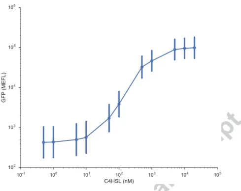
As discussed above, engineered E. coli was used to test the delivery of the signaling molecules from microrobots. These cells express GFP in the presence of C4HSL. To determine the concentration of C4HSL needed to induce the optimal expression, dose response curve for C4HSL induction in
E. coli was measured; as shown in Fig. 5. pNDW2 was transformed into NEB 10-Beta
compe-tent cells. A single colony was inoculated in 200 µL of M9-Minimal Media supplemented with glycerol[21] overnight shaking at 900 RPM at 37◦C. The next day cultures were diluted 178-fold and subcultured for 3 hours at 900 RPM at 37◦C. Subcultures were then diluted 13-fold and 5 µL used to inoculate 145 µL of media with varying concentrations of C4HSL and grown for 5 hours at 900 RPM at 37◦C. Flow cytometry was performed at 0.5 µL/s on 10-fold diluted samples in 1X Phosphate-Buffered Saline and analyzed using Cytoflow (https://github.com/bpteague/cytoflow) to report Molecules of Equivalent Fluorochrome Levels (MEFL). As seen from the figure >100 nM of C4HSL is required for succesful gene expression in these cells[29]. We chose a 100 fold higher final concentration (100 µM) of C4HSL for induction in the cells. Since the concentration of the adsorbed linker in the microcylinder solution was not quantified, the concentration of C4HSL on the microrobots was assumed to be equal to the starting C4HSL solution (100 mM as shown in the previous section). Therefore, 5 µL of the microrobot solution was added to 5 mL of bacterial culture to give a final concentration of 100 µM for the linker.
Imaging was performed on a Zeiss upright microscope using bright field and fluorescence. Videos were captured using a CCD camera, and video processing was performed using ImageJ. The linker was cleaved using UV light, delivered via DAPI filter having an excitation wavelength of 350 nm, fitted on the Zeiss microscope. The solution was exposed to UV light for 120 seconds. Fluorescent images of bacterial cells were acquired using a GFP filter having an emission of 507 nm and excitation of 488 nm. The cell culture was imaged using fluorescence microscopy at definite time intervals. All the images were adjusted for threshold and processed in ImageJ.
4
RESULTS
4.1
Protein expression with light-activated signaling molecule
To observe protein expression due to delivery of the signaling molecules using microrobots, 5 µL of the microrobot solution was added to 5 mL of liquid bacterial culture. Then the liquid bacterial culture was exposed to UV light for 120 seconds. As seen in Fig. 6(a), just after exposure to UV light (T = 0 hrs), there is no fluorescent signal, since the NEB 10-beta cells transformed with pNDW2 plasmid have just been induced. At 3 hours past light exposure, a fluorescent signal was seen indicating that there is free C4HSL in the system regulating protein expression. The fluorescent signal intensity increases with time due to the increase in cell density, which is evident at T = 8 hrs. For proof-of-principle, 5 µL of the microrobot solution was added to another bacterial culture with the same plasmid. However this system was not exposed to UV light. Fig. 6(b) denotes the fluorescent images from that sample. The lack of GFP signal over the time period of the experiment shows that our microrobotic system delivers C4HSL only with the application of a light signal.
Figure 5: Dose response curve of pNDW2 to exogenously provided C4HSL. Each point is the geometric mean of a population of at least 1000 cells, error bars represent the standard deviation within that population.
Figure 6: (a) After addition of the microrobots (with 100 µM of photochemical linker), the culture is exposed to UV light. At the start of the experiment (T = 0 hrs), there is no fluorescent signal. After 3 hrs, the observed fluorescent intensity has increased, denoting that the cells are expressing GFP. At T = 8 hrs, the fluorescent signal intensity has further increased, as expected due to the increase in cell growth. (b) The microcylinders with the linker were again added to the bacterial cell culture. However, keeping all the other conditions same, the sample was not exposed to UV. The lack of fluorescent expression at T = 0, 3 and 8 hrs demonstrates that there was no protein regulation, pointing to the lack of free C4HSL in the system.
Figure 7: (a) The fluorescent expression from E. coli with pNDW1 which have been engineered to express GFP, without the addition of any chemical input is recorded over the length of the experiment. The intensity of fluorescence increases over time as is expected. (b) NEB beta-10
E. coli transformed with pNDW2 plasmid, which respond to the signaling molecule of interest,
were induced with 100 µM of C4HSL in DMSO. As expected the intensity is zero at the start of experiment since the cells were just induced. With time the fluorescence intensity increases indicating successful gene expression in the cells.
Figure 8: The fluorescent expression from genetically modified NEB beta-10 E. coli with pNDW2 without any induced C4HSL is demonstrated.
4.2
Protein expression without light-activated signaling molecule
To quantify the efficacy of our system, we also perform three controls. The first consists of NEB 10-beta E.coli transformed with pNDW1 plasmid, which express GFP constitutively. Due to the constitutive production of GFP, the fluorescence response of this system is the highest and increases over time, as seen in Fig. 7(a). The fluorescent GFP signal from this culture is in the absence of any chemical signal and increases over the period of 8 hours, as expected due to cell growth. The second benchmark for our system consists of the NEB 10-beta E. coli with pNDW2 plasmid, induced with exogenous C4HSL. The protein expression of the cells with response to 100 µM exogenous C4HSL can be seen in Fig. 7(b). This control is analogous to Fig. 6, and successful protein expression in the bacterial cells with exogenous C4HSL can be observed increasing over time. The fluorescence expression from the engineered E.coli with pNDW2 without any induction is shown in Fig. 8.
4.3
Magnetic actuation of the robots
Two methods of actuation for the microrobots were used. The first method was using a permanent magnet. In this case, the microrobots had a velocity of 0.3 ± 0.4 µm/s. We also used the four in plane magnetic coils to propel the microcylinders in solution. The average speed obtained
was 0.5± 0.3 µm/s. The speeds above were obtained by averaging over 10 particles. Since the experimental system can have environmental disturbances and convection, a large deviation in the speed of the microrobots was observed. Thus, control over microrobot speed is challenging in the present system. However the direction of motion of microrobots can be accurately controlled due to the four coil magnetic system. The generated gradient in the four coil magnetic system is on the order of 50 mT/m.
4.4
Protein expression with directed microrobots
To highlight the successful protein expression in bacterial cells using magnetically driven micro-robots, we grow a carpet of NEB 10-beta E. coli with pNDW2 plasmid on top of a standard agar plate. This carpet or cellular lawn sits on top of the agar plate and contains the bacterial cells. 2% w/v solution of the microcylinders was added onto the cellular lawn, on top of the agar in the center. The microcylinders were then directed to cells in the cellular lawn using the electromagnetic coil system, which demonstrates that clusters or swarms of microrobots can be directed to cell cultures. Then the system was exposed to UV light using DAPI filter for 120 seconds. Previous studies [30, 31] have demonstrated that the bacterial cells are not affected by the UV exposure (at 365 nm) especially in the doses (5 mW/cm2) used in the following experiments. Fig. 9 shows the fluorescent image of the system and the cellular response. In Fig. 9(a) the fluorescent image is taken at T = 0 hrs and as expected there is no fluorescence. The corresponding brightfield image is shown in Fig. 9(b). Fig. 9(c) shows the control which consists of the bacterial cell population with the microrobots at T = 4 hrs where the microrobots were not exposed to the UV light. Since the cells were not induced by diffused C4HSL, no fluorescence was observed. In contrast, Fig. 9(d) shows the corresponding image of microrobots interfaced with cells at T = 4 hrs. As can be seen from the figure, the areas with the microrobots show fluorescence expression. On exposure to UV light the cleavable linker releases C4HSL which diffuses in the bacterial cells, leading to the protein expression. To highlight the localized payload delivery, Figure 10 contrasts the brightfield and fluorescence images of the microrobots in cell culture media, after exposure to UV light. The microcylinders with the linker were added into the cell culture solution and directed to cellular cultures. Then the system was exposed to UV light. In Figure 10(a) the brightfield image shows the microrobots in the cell solution at T = 3 hrs. We image the cells that have formed clusters on the glass surface as indicated by the white circles in the figure. In contrast, Figure 10(b) shows the corresponding fluorescence image. As can be seen, the areas with the bacterial cells show fluorescence expression while the surrounding areas are dark.
5
Discussion
The differences in fluorescent intensity seen between our proof-of-concept experiments and the control experiments are to be expected. The cells in Figure 7(a) are constitutively expressing GFP, therefore we would expect the maximum expression from these cells.The engineered E. coli used in our system express GFP only in response to C4HSL. Therefore the protein expression is dependent on induction of the cells with the signaling molecule. After induction the fluorescence intensity increases as the cells grow and divide, however the intensity of response would be lower than the control cells. Also of importance is the difference in expression between Fig. 6(a) and Fig. 7(b). From the images, the intensity of fluorescence expression with the cleaved linker is less than the fluorescence intensity obtained by using pure C4HSL, for identical time points. This could be due to multiple factors. The actual concentration of the adsorbed linker on the robot surface is unknown. Thus, it is possible that the concentration of the photochemical linker is low. Lower concentration might lead to insufficient amount of C4HSL available to the cells in the population, resulting in lower expression. Another reason could be the incomplete cleavage of all the linker molecules after exposure to UV, resulting in reduced concentration of C4HSL in the system[32]. The other factor that needs to be investigated is the effect of reaction products which are generated in the system after photochemical exposure, on the viability of the cells. All of these are the subjects of future study.
Figure 9: (a) The fluorescent image of microcylinders dispersed on the bacterial cell culture in agar at T=0 hrs at 15X (b) The corresponding brightfield image of the workspace at 15X (c) The fluorescent image of microcylinders dispersed on the bacterial cell culture in agar at T= 4 hrs at 15X, in the absence of UV light (d) The fluorescent image of the microcyliners corresponding to (a) and (b) at T = 4 hrs. The bright spots correspond to the cells expressing GFP.
Figure 10: (a) The brightfield image of the microcylinders in dilute bacterial cell solution at T = 3 hrs. Cells can be seen at the lower right and middle of the workspace as denoted in white. The cylinders (outlined) are dispersed on the surface. (b) The corresponding fluorescence image of the workspace; the bright spots correspond to the cells expressing GFP.
5.1
Limitations of the system
Even though swarms of microrobots can be accurately controlled and steered in solution, indepen-dent control of multiple microrobots in the same workspace is an ongoing challenge in robotics[18]. Thus, we can steer multiple microrobots to cell clusters; however directing an individual micro-robot in the swarm, independently of the swarm is challenging. Also, the current photochemical linker used in our system is irreversible. Once the signaling molecule has diffused following the cleavage, the microrobots cannot be used for delivery of the signaling molecule again. However, there are reversible photolabile linker systems where the signaling molecule is reversibly bound to the microrobot and can be recovered after cleavage. This is a subject of future study.
The UV dose used in our system is very low and doesn’t affect bacterial cells. Thus, our system can be used for all biomedical applications involving bacteria. The wavelength of UV light used is also long and doesn’t induce DNA damage. In the future we would like to extend this system to mammalian cells. However, the effect of the UV dose on mammalian cells would need to be quantified. To this effect, we intend to make linkers that can be dissociated by using near infrared light which is compatible with mammalian cells.
5.2
Extension to helical microrobots
To extend the design of microrobots, alternative geometries were investigated. One of the geome-tries chosen was that of helical microrobots. Helical microrobots offer multiple advantages over cylindrical microrobots. The primary advantage of working with helical geometry is that the robots can be moved by rotating the direction of the magnetic field rather than creating strong magnetic field gradients for pulling, which requires significantly higher field strengths[3]. In low Reynolds number regime, helical propulsion is always more efficient than gradient pulling, as outlined by Abbot et. al.[33]. Helical microrobots also have greater surface area, so they can theoretically adsorb more molecules and subsequently increase the delivery efficiency. Helical microrobots are also easier to fabricate using maskless Direct Laser Writing in contrast to photolithography for cylindrical microrobots.
The helical structure of the microrobots was fabricated via two-photon polymerization with the NanoScribe Photonic Professional GT. The double helix structure was printed using IP-S photoresist with a length of 37.5 µm and width of 18.75 µm. The microrobots were coated on one side with Ni/TiO2 bilayer, making them magnetic. A 55 nm thick layer of Nickel (>99.9%
Sigma Aldrich) followed by 15 nm of Titanium dioxide was evaporated onto the microrobots under vacuum in a Lesker PVD75 electron beam evaporator and DC/RF Sputterer (Nanofabrication lab, University of Pennsylvania). Fig. 11(a) shows the array of helical microrobots after deposition of the metal bilayer at 30X. The helical robots were manually dislodged from the array by using micropipettes. The process of obtaining a single helical microrobot from the array is shown in video 1 at 10X magnification. A single helical microrobot being placed in a solution of DI water by the micropipette is shown in Fig. 11(b).
To test the response of the coated helical microrobots to a magnetic field, a permanent magnet was used. The response of the helical microrobots to the permanent magnet can be seen in video 2 and 3. A single microrobot with 10 µm non-magnetic polystyrene particles as control particles, was tested with the four coil magnetic setup. In Video 2, the helical microrobots are actuated using the four coil magnetic setup while the non magnetic particles have no response, illustrating the successful magnetization of the microrobots. In addition, a single helical microrobot was placed in DI water in video 3 and its response to a permanent magnet was observed. The movement of the microrobot could be seen, thus confirming the magnetization. Fig. 11(c) show the helical microrobot in solution with the non-magnetic polystyrene particles.
6
Future Work
The above results open up the possibility of targeted gene expression in cells. Our method of delivering chemical payloads offers some significant advantages over traditional delivery methods. The biggest advantage is the versatility of the system. The photochemical linker developed here is a very general linker and can be adapted to a wide variety of molecules with very little modification. This manuscript serves as a proof of concept for the delivery system. In the future we would like to extend this system for delivery of proteins, especially targeted delivery in cellular cultures. Our
Figure 11: (a) Brightfield image of a helical microrobot array at 30X. (b) Brightfield image of the micropipette after placing a helical microrobot in DI water at 10X. The microrobots are outlined in the image. (c) Brightfield image of single helical microrobot with 10 µm non-magnetic polystyrene particles as control particles.
method also overcomes the problem of leakage and uncontrolled diffusion of payloads associated with other delivery systems. The microrobots can be steered on the cellular substrate. Once on target, light can be used to release and deliver the desired chemical signal to that position. In our light activated delivery system, the active chemical or payload, namely the signaling molecule, is caged or inactive on the surface of the microrobot. The chemical payload can only become active or diffuse into the cells on exposure to light. We have essentially devised a ‘trigger’ for diffusion. Therefore, leakage or diffusion of the payload does not affect the gene expression in our system. In future work, the light-activated delivery method would be extended to helical microrobots. Integrating the helical microrobotic system with targeted gene expression in engineered cells is an active area of future work.
7
CONCLUSION
In this work, we have introduced a light activated delivery system combined with a microrobotic platform for on-demand delivery of biologically significant payloads. Our microrobotic platform is comprised of magnetic microcylinders surface functionalized with a photocleavable linker. For proof-of-concept, the photocleavable linker was optimized for C4HSL and engineered E. coli cells. We demonstrate that on exposure to light, the delivery mechanism was able to deliver C4HSL to the bacterial cells leading to the desired fluorescence response which denotes successful gene regulation. These robots can be actuated by low-strength magnetic fields, which are safe for cells and tissue and were added to bacterial cells in vitro. In contrast, absence of light leads to no gene expression and no fluorescence response. In this work, we have also designed a helical microrobotic platform. We demonstrate a microprinting based method of synthesizing micron-scale helical robots, which will be explored for integration with engineered cells in subsequent works. On-demand delivery of signaling molecules would open up exciting new possibilities in biology, especially for designing patterns in cellular systems. For example, quorum sensing bacteria have been shown to form Turing patterns using C4HSL as inducers [21]. Steering of the microrobots to specific regions of the cell system, in user-defined patterns, and subsequent release of the signaling molecule would enable us to form spatio-temporal gradients of signaling molecules. As discussed above these patterns of signaling molecules are the basis of cellular communication. The ability to create artificial cellular patterns with spatio-temporal control would revolutionize the fields of synthetic biology, morphogenesis and tissue engineering.
References
[1] L. Ricotti, B. Trimmer, A. W. Feinberg, R. Raman, K. K. Parker, R. Bashir, M. Sitti, S. Mar-tel, P. Dario, and A. Menciassi, “Biohybrid actuators for robotics: A review of devices actuated by living cells,” Science Robotics, vol. 2, no. 12, 2017.
[2] K. E. Peyer, L. Zhang, and B. J. Nelson, “Bio-inspired magnetic swimming microrobots for biomedical applications,” Nanoscale, vol. 5, pp. 1259–1272, 2013.
[3] E. E. Hunter, E. W. Brink, E. B. Steager, and V. Kumar, “Toward soft micro bio robots for cellular and chemical delivery,” IEEE Robotics and Automation Letters, vol. 3, no. 3, pp. 1592–1599, July 2018.
[4] S. Yim, K. Goyal, and M. Sitti, “Magnetically actuated soft capsule with the multimodal drug release function,” IEEE/ASME Transactions on Mechatronics, vol. 18, no. 4, pp. 1413–1418, Aug 2013.
[5] H. Wang, Q. Huang, Q. Shi, T. Yue, S. Chen, M. Nakajima, M. Takeuchi, and T. Fukuda, “Automated assembly of vascular-like microtube with repetitive single-step contact manipu-lation,” IEEE Transactions on Biomedical Engineering, vol. 62, no. 11, pp. 2620–2628, Nov 2015.
[6] N. J. Bainton, B. W. Bycroft, S. R. Chhabra, P. Stead, L. Gledhill, P. J. Hill, C. E. Rees, M. K. Winson, G. P. Salmond, G. S. Stewart, and P. Williams, “A general role for the lux autoinducer in bacterial cell signalling: control of antibiotic biosynthesis in erwinia,” Gene, vol. 116, no. 1, pp. 87 – 91, 1992.
[7] S. Das, E. E. Hunter, N. A. DeLateur, E. B. Steager, R. Weiss, and V. Kumar, “Controlled delivery of signaling molecules using magnetic microrobots,” in 2018 International Conference on Manipulation, Automation and Robotics at Small Scales (MARSS), July 2018, pp. 1–5. [8] S. Fusco, F. Ullrich, J. Pokki, G. Chatzipirpiridis, B. Ozkale, K. Sivaraman, O. Ergeneman,
S. Pané, and B. Nelson, “Microrobots: A new era in ocular drug delivery,” vol. 11, pp. 1–12, 07 2014.
[9] H. Ceylan, J. Giltinan, K. Kozielski, and M. Sitti, “Mobile microrobots for bioengineering applications,” Lab Chip, vol. 17, pp. 1705–1724, 2017.
[10] T. Xu, J. Yu, X. Yan, H. Choi, and L. Zhang, “Magnetic actuation based motion control for microrobots: An overview,” Micromachines, vol. 6, no. 9, pp. 1346–1364, 2015.
[11] Y. Yang, J. Mu, and B. Xing, “Photoactivated drug delivery and bioimaging,” Wiley Interdisciplinary Reviews: Nanomedicine and Nanobiotechnology, vol. 9, no. 2, pp. n/a–n/a, 2017.
[12] U. Bozuyuk, O. Yasa, I. C. Yasa, H. Ceylan, S. Kizilel, and M. Sitti, “Light-triggered drug release from 3d-printed magnetic chitosan microswimmers,” ACS Nano, vol. 12, no. 9, pp. 9617–9625, 2018, pMID: 30203963.
[13] F. Qiu, S. Fujita, R. Mhanna, L. Zhang, B. R. Simona, and B. J. Nelson, “Magnetic helical mi-croswimmers functionalized with lipoplexes for targeted gene delivery,” Advanced Functional Materials, vol. 25, no. 11, pp. 1666–1671, 2015.
[14] J. Pearson, E. Pesci, and B. Iglewski, “Roles of pseudomonas aeruginosa las and rhl quorum-sensing systems in control of elastase and rhamnolipid biosynthesis genes,” Journal of bacteriology, vol. 179, no. 18, pp. 5756–5767, September 1997.
[15] P. Erkoc, I. C. Yasa, H. Ceylan, O. Yasa, Y. Alapan, and M. Sitti, “Mobile microrobots for active therapeutic delivery,” Advanced Therapeutics, vol. 2, no. 1, p. 1800064, 2018.
[16] H. Ceylan, J. Giltinan, K. Kozielski, and M. Sitti, “Mobile microrobots for bioengineering applications,” Lab on a Chip, vol. 17, no. 10, pp. 1705–1724, 2017.
[17] S. Tottori, L. Zhang, F. Qiu, K. K. Krawczyk, A. Franco-Obregon, and B. J. Nelson, “Magnetic helical micromachines: Fabrication, controlled swimming, and cargo transport,” Advanced Materials, vol. 24, no. 6, pp. 811–816, 2012.
[18] S. Das, E. B. Steager, K. J. Stebe, and V. Kumar, “Simultaneous control of spherical microrobots using catalytic and magnetic actuation,” in 2017 International Conference on Manipulation, Automation and Robotics at Small Scales (MARSS), July 2017, pp. 1–6. [19] S. Das, E. B. Steager, M. A. Hsieh, K. J. Stebe, and V. Kumar, “Experiments and open-loop
control of multiple catalytic microrobots,” Journal of Micro-Bio Robotics, vol. 14, no. 1, pp. 25–34, Jun 2018.
[20] E. Weber, C. Engler, R. Gruetzner, S. Werner, and S. Marillonnet, “A modular cloning system for standardized assembly of multigene constructs,” PLoS ONE, vol. 6, no. 2, p. e16765, 2011. [21] D. Karig, K. M. Martini, T. Lu, N. A. DeLateur, N. Goldenfeld, and R. Weiss, “Stochastic Turing patterns in a synthetic bacterial population,” Proceedings of the National Academy of Sciences, vol. 115, no. 26, pp. 6572–6577, jun 2018.
[22] P. Klan, T. Solomek, C. G. Bochet, A. Blanc, R. Givens, M. Rubina, V. Popik, A. Kostikov, and J. Wirz, “Photoremovable protecting groups in chemistry and biology: Reaction mecha-nisms and efficacy,” Chemical Reviews, vol. 113, no. 1, pp. 119–191, 2013, pMID: 23256727. [23] B. Neises and W. Steglich, “Simple method for the esterification of carboxylic acids,”
Angewandte Chemie International Edition in English, vol. 17, no. 7, pp. 522–524, 1978. [24] C. L. Coon, W. G. Blucher, and M. E. Hill, “Aromatic nitration with nitric acid and
trifluo-romethanesulfonic acid,” The Journal of Organic Chemistry, vol. 38, no. 25, pp. 4243–4248, 1973.
[25] T. Suhs and B. Konig, “Synthesis of functionalized guanidino amino acids,” Chemistry-A European Journal, vol. 12, no. 31, pp. 8150–8157, 2006.
[26] S. Tang, J. Wang, Q. Zhu, Y. Chen, and X. Li, “Preparation of rutile tio2 coating by thermal chemical vapor deposition for anticoking applications,” ACS Applied Materials & Interfaces, vol. 6, no. 19, pp. 17 157–17 165, 2014, pMID: 25192018. [Online]. Available: https://doi.org/ 10.1021/am5048762
[27] Y. Paz, “Self-assembled monolayers and titanium dioxide: From surface patterning to potential applications,” Beilstein Journal of Nanotechnology, vol. 2, pp. 845–861, 2011.
[28] A. G. Thomas and K. L. Syres, “Adsorption of organic molecules on rutile tio2 and anatase tio2 single crystal surfaces,” Chem. Soc. Rev., vol. 41, pp. 4207–4217, 2012. [Online]. Available: http://dx.doi.org/10.1039/C2CS35057B
[29] E. C. Pesci, J. P. Pearson, P. C. Seed, and B. H. Iglewski, “Regulation of las and rhl quorum sensing in pseudomonas aeruginosa.” Journal of bacteriology, vol. 179, no. 10, pp. 3127–3132, 1997.
[30] A. Loeschcke, D. Binder, T. Drepper, K.-E. Jaeger, A. Grünberger, C. Probst, D. Kohlheyer, W. Wiechert, J. Pietruszka, and C. Bier, “Light-responsive control of bacterial gene expression: precise triggering of the lac promoter activity using photocaged IPTG,” Integrative Biology, vol. 6, no. 8, pp. 755–765, 06 2014. [Online]. Available: https://doi.org/ 10.1039/c4ib00027g
[31]
[32] Y. V. Il’ichev, M. A. Schworer, and J. Wirz, “Photochemical reaction mechanisms of 2-nitrobenzyl compounds: Methyl ethers and caged atp,” Journal of the American Chemical Society, vol. 126, no. 14, pp. 4581–4595, 2004, pMID: 15070376.
[33] J. J. Abbott, K. E. Peyer, M. C. Lagomarsino, L. Zhang, L. Dong, I. K. Kaliakatsos, and B. J. Nelson, “How should microrobots swim?” The International Journal of Robotics Research, vol. 28, no. 11-12, pp. 1434–1447, 2009.