READ THESE TERMS AND CONDITIONS CAREFULLY BEFORE USING THIS WEBSITE.
https://nrc-publications.canada.ca/eng/copyright
Vous avez des questions? Nous pouvons vous aider. Pour communiquer directement avec un auteur, consultez la
première page de la revue dans laquelle son article a été publié afin de trouver ses coordonnées. Si vous n’arrivez pas à les repérer, communiquez avec nous à [email protected].
Questions? Contact the NRC Publications Archive team at
[email protected]. If you wish to email the authors directly, please see the first page of the publication for their contact information.
NRC Publications Archive
Archives des publications du CNRC
This publication could be one of several versions: author’s original, accepted manuscript or the publisher’s version. / La version de cette publication peut être l’une des suivantes : la version prépublication de l’auteur, la version acceptée du manuscrit ou la version de l’éditeur.
Access and use of this website and the material on it are subject to the Terms and Conditions set forth at
Investigating large gray cast iron pipe failures: a step by step approach Makar, J. M.
https://publications-cnrc.canada.ca/fra/droits
L’accès à ce site Web et l’utilisation de son contenu sont assujettis aux conditions présentées dans le site LISEZ CES CONDITIONS ATTENTIVEMENT AVANT D’UTILISER CE SITE WEB.
NRC Publications Record / Notice d'Archives des publications de CNRC:
https://nrc-publications.canada.ca/eng/view/object/?id=8481add2-9152-434f-89aa-34c72def90a8 https://publications-cnrc.canada.ca/fra/voir/objet/?id=8481add2-9152-434f-89aa-34c72def90a8
Investigating large gray cast iron pipe
failures: a step by step approach
Makar, J. M.
A version of this paper is published in / Une version de ce document se trouve dans : American Water Works Association Infrastructure Conference, 2001, pp. 1-16
www.nrc.ca/irc/ircpubs
Investigating Large Gray Cast Iron Pipe Failures: A Step
by Step Approach
Jon Makar, Ph.D. Research Officer
Institute for Research in Construction National Research Council Canada
1500 Montreal Road
Ottawa, Ontario K1A 0R6 Canada
Abstract:
Pipe failures are a common problem for all water utilities. This paper describes a step by step approach for determining the causes of those failures. This process is particularly important for investigating failures in important pipelines where the failure may have had significant social or economic costs. The steps presented include actions that should be taken to prepare for a failure analysis, work that should be done during the repair of the failed pipe and the failure analysis itself. These steps are intended to provide suggestions for water utilities and their consultants in dealing with failures of gray cast iron pipe, not as prescriptive guidelines.
Introduction:
Many water utilities have aging, large diameter gray cast iron pipes. Failures in these pipes can be very expensive, cutting water supply to a large numbers of customers and sometimes producing millions of dollars in damage. Understanding the causes of these failures is essential to preventing a repetition on the same line.
Despite the expense and problems caused by water pipeline failures, most research has concentrated solely on investigating the effect of corrosion pitting1-4. Other factors affecting the failures of these pipes have largely been ignored by the academic community. The National Research Council Canada (NRC) has recently completed a three year study of gray cast iron pipe failures. This work has examined the impact of external and internal applied forces, manufacturing defects and human error on these failures in particular. Details of the results of the study have been given elsewhere5-7, but some of the major findings include:
• Formal identification of the major failure modes experienced by gray cast iron pipes;
• Identification of multi-event failures, where the pipe partially cracks and continues to function in a damaged condition;
• Recognition of the high level of variability in the mechanical behaviour of cast iron and the consequent need for multiple samples during any program of mechanical testing; and
• Recognition of the significant role that manufacturing defects play in some pipe failures.
Eighty four failure analyses have been conducted to date as part of the research program.
The research has also resulted in a number of contacts with water utilities, consultants, contractors and lawyers. These contacts and subsequent studies of failure analysis reports have suggested that there is no widely accepted standard practice for analysing failed water mains. In some cases specific tests that could have provided useful or essential information for the failure were not carried out or carried out on the wrong material. Part of the difficulties the industry has experienced in this regard appear to be due to a discontinuity between the expertise of the engineers who carry out the failure analysis and those who need to understand and implement its results. The failure analysis is usually conducted by a metallurgical engineering or failure analysis consultant. However, the work of these consultants typically considers only the condition of the metal itself. Their report needs to be combined with the knowledge of the water utility or civil engineering consultants in order to completely understand why the pipe has failed and prevent further problems. In addition, the water utility needs to ensure that the consultants are given the appropriate samples and information necessary to complete the investigation.
The need for general guidelines for gray cast iron failure analysis led to the work presented in this paper. The paper presents a step by step description of how to conduct a failure analysis, starting with preparations to be undertaken before a failure occurs, working through the investigation itself and finishing with the decision making process. However, failure analysis is most frequently encountered by the water industry (and many others) as a consequence of legal action. It is therefore necessary to state that the information here represents the current state of a work in progress. It is presented to provide suggestions for the work of water utilities and failure analysis consultants, not as the final word on the subject of how the failure of these pipes should be investigated. Each jurisdiction has its own requirements for legally related failure analysis work. Local legal and failure analysis experts should be consulted to determine those requirements before undertaking any failure analysis in conjunction with a legal action.
Preparations
This section only considers the preparations necessary to conduct the failure analysis itself. Other work, such as performing a risk evaluation of the pipeline or determining the consequences of a failure are not discussed here.
Step 1. Decide on when a failure analysis should be performed.
Failure analysis works best when the work crew making the pipe repair is informed beforehand that a failure analysis will be required. Without preparation, mistakes can be made which will make the analysis more difficult or impossible. Repair crews should therefore know what they will be required to do at the failure site and when they should do it.
The nature of this decision will depend on what goal the water utility wants to achieve with the failure analysis. Failure analysis of pipes in the distribution system is rarely worthwhile as an exercise in itself. Most water utilities will undergo a significant number of distribution system failures each year8. Trying to do a full failure analysis of each distribution failure will be expensive and may not give new information about the condition of the system. Instead, a simple sketch or photograph of the failure for the utility’s records is all that may be necessary. A full failure analysis in small diameter pipes may be useful in specific cases such as part of a sampling program, for legal purposes, to determine whether particular types of failures are occurring in the utility’s system, or to determine the reasons why a particular line is having a high failure rate.
In contrast, failures in large diameter transmission pipes should generally be investigated in more detail. The cost, inconvenience and hazards associated with a large diameter failure are such that a full failure analysis is generally worthwhile. It will not only provide information about why the failure took place, but may be very important for preventing future failures. More detailed records may also need to be kept for legal purposes.
Simple guidelines should therefore be established as to the type of pipes in the utility’s system that will be examined in detail in the event of a failure. These guidelines should consider not only the pipe diameter, but also the pipe material and the nature of the failure. The following classification system may be useful in composing the guidelines:
Class I failures: Routine pipe breaks that are repaired as they occur. Example: day to day small diameter gray cast iron failures.
Class II failures: Pipe failures that would ordinarily be considered class III, but that will be investigated more thoroughly as part of a larger program of research into the behaviour of the system or a local area. A full or partial analysis of the failure is carried out for internal use only. Examples: Small diameter gray cast iron failures during a sampling campaign, pipes in a region with higher than expected failure rates.
Class III failures: Pipe failures with serious consequences in terms of number of customers losing water supply, damage to surrounding environment and/or other direct, indirect or social costs. This failure analysis should be conducted on the assumption that it will be reviewed by other interested parties, such as utility managers, local politicians or litigants. Examples: Large diameter pipe failures, small diameter failures on lines that lead to hospitals or water intensive industries, failures that may result in litigation.
In general, the higher the class of failure, the more complete the required failure analysis. Class I failures require little or no investigation. Class II failures will require a partial or complete investigation, depending on the reason for the work. Class III failures
will generally require a complete investigation, using the full range of procedures described in the remainder of this paper.
Step 2. Decide on a standard approach to dealing with the failure
Once a decision has been made as to when failure analysis should be performed, the next step is decide, in advance, how it will be done and who will do the work. The question of how includes setting up standard procedures to be followed such as are discussed in the rest of this document. It should also include determining who should be contacted to conduct the failure analysis and the equipment to be taken to the site of the failure.
The question of who will do the work includes both internal staff and external consultants. Internally, a decision should be made as to whether a particular crew will be responsible for repairing all failures that will be investigated. Using a single crew for more complicated failures may be advantageous both in terms of the speed of the repair and ensuring that the necessary samples are collected. In addition, the water utility may wish to appoint a technologist or other responsible person to the task of collecting the samples. This person should be made known to the actual repair or emergency response crews and should be available to be called to a failure site as required.
Externally, a metallurgical engineering or failure analysis firm is likely to be required to conduct part of the investigation. Local firms who may be able to do the necessary work, including mechanical testing and metallography, should be identified and their capabilities determined. Similarly, civil engineering consultants may be required to analyse the structural behaviour of the pipe and assist in the final decision making process.
During the failure
This section of the paper deals only with issues related to the failure analysis itself, not repair procedures or other aspects of a response to a serious pipe failure. While water utilities should consider developing standard procedures for this type of incident, they are outside the area of discussion here. Instead, the paper is intended to cover only what should be done from a technical point of view to determine the cause breaks in gray cast iron mains.
Step 3 - Record events during the failure
Video and still cameras should be taken to the site of the failure and used to record the failure and repair process. This task could be undertaken by the same person who is responsible for collecting the samples for the failure analysis, by a crew foreman or by management personnel. Pictures and video tapes should be taken of the entire event, starting from the arrival on the site to the removal of the necessary samples. Written notes should also describe relevant events. The recordings and pictures will help to determine the exact location from which the samples were taken and the orientation of the samples to the rest of the pipe. They may provide important information as to the
condition of the pipeline before it failed. The videos may also be useful for analysing the repair crew’s performance and determining where improvements in technique can be made. The still photographs should concentrate on details that may not show up well on the video tape. Any evidence of factors that may have contributed to the failure, such as a truck parked in the vicinity of the failed pipe or the presence of a thrust block, should also be recorded.
Step 4 - Take Soil Samples
Once the water flow from the pipe has been shut off, soil samples should be taken from the soil around the failure. At least two samples each should be taken from the remaining soil at the point of the break, soil at the pipe level upstream of the break and soil at the break point but closer to the top of the hole exposed during the repair. The flow of water from the failure will likely have affected any local soil chemistry, with the samples nearest the failure being the most strongly affected. The samples from above the pipe and upstream of the water flow may be helpful in understanding the soil chemistry before the failure. These samples should be placed in a double polyethelyne bag, which should be tied tightly shut. A tag identifying the location of the sample and the time its was taken should be attached to the bag. Each sample should then be placed in a metal tin similar to a 4 litre paint can and the lid sealed. The information about location of the sample and the time it was taken should also be written on the tin. Sealing the sample within the bag and metal tin will ensure that the soil sample does not dry out before it can be tested.
Step 5 – Collecting pipe samples
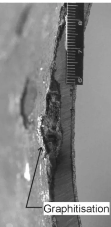
The top of the pipe should be marked to facilitate the failure analysis. The length of pipe to be removed should then be determined and the pipe marked accordingly. The exact length will depend on the failure mode. Water pipes tend to fail either by some form of fracture or by corrosion causing a hole to develop. (The failure of joint seals and appurtenances are separate matters). If a fracture of some kind has occurred, the entire length of broken pipe should be removed. All pieces should be recovered, since they may be necessary to determine the cause of the failure. If the failure is due to a corrosion pit the pitted area should be removed. Once the removal has taken place, the exposed metal at the edges of the pipe should be examined for signs of graphitisation (Figure 1). If graphitisation is visible that appears to be part of the same corrosion pit that caused the failure, additional pipe material should be taken so that the size of the corrosion pit can be determined.
The removal of the pipe sample from the ground should be recorded. In particular, the person in charge of collecting the sample needs to make sure that all of the pipe that shows signs of the failure is removed. He or she also needs to record any damage done to the pipe in the process of removal so that this damage will not be mistaken for that produced during the pipe failure.
Figure 1. Graphitisation along a saw cut on a ductile iron pipe.
After the failure
Step 6 - Collect background records
Pressure surges are potential contributing factors to pipeline failures. The best possible pressure records for the failed pipeline should be obtained, whether they are simply the standard operating pressure expected within the pipe or continuous records of the actual pressure experienced near the failure point. Similarly, frost and temperature changes can produce significant loads on the pipe. The current temperature, depth of frost and the temperature trends for the time preceding the break should be collected. Other relevant data includes the depth of burial, the age of the pipe, the pipe material, the class of the pipe and the standards with which the pipeline would have been designed.
Step 7 - Conduct a preliminary examination
Failures of metallic water pipes can be largely divided into two categories – corrosion failures and mechanical failures. Mechanical failures may have corrosion problems associated with them, but are due to the pipe no longer being able to resist applied forces. Corrosion failures are produced by through holes or thinning of the pipe due to corrosion to the point where normal water pressure will blow out the thin skin of metal that remains. The remaining procedures and decisions that need to be made will depend on the type of failure. The preliminary examination will establish the basic type of failure.
Generally the decision on whether the pipe failed due to corrosion pitting or some form of mechanical failure can be made based on the visual appearance of the failure. Exposed fracture surfaces and cracks indicate mechanical failures, while corroded surfaces indicate a corrosion pit failure. Some examples of these different types of failures may be found in a paper to be presented at the 2001 International Conference on Underground Infrastructure Research7. In some cases what is essentially a corrosion pit failure may produce a large hole with fracture surfaces along some or all of the edges when internal water pressure causes the pipe to fail before the corrosion had completely penetrated the wall. These failures may be initially described as mechanical and may not be identified as corrosion induced until further into the analysis process.
Step 8 – First structural analysis for mechanical failures
Mechanical failures are complicated to investigate and interpret. As a first step, a civil engineer from the utility or a consultant should examine the failed pipe and determine the types of forces that were likely to have caused the failure. Subsequent steps in the failure analysis may require destructive tests, so an examination at this point is helpful to ensure that the engineer has a clear picture of the appearance of the pipe before samples are taken from it. Understanding the likely forces behind the failure may also prove helpful in providing guidance to the consultant undertaking the failure analysis.
Five different failure modes have been identified so far beyond simple corrosion failures. They include:
• circumferential failures, which typically occur in smaller diameter pipes;
• longitudinal splits, which are normally found in large diameter pipes;
• spiral failures, which are found in medium diameter pipes, typically between 41 to 51 cm (16-20 in.) in diameter;
• bell splits, which may be found in any pipe sealed with leadite, a sulphur based joint sealer; and
• shearing failures, which are also normally found in large diameter pipes.
Circumferential breaks are due to bending moments in the pipe. Small diameter pipes are particularly susceptible to this type of failure due to their low moment of inertia and their long beam length in proportion to their diameter. Larger diameter pipes have much higher moments of inertia. They also have much lower beam length to diameter ratios. Longitudinal splits travel down part or most of the length of a pipe and may be caused by internal water pressure or compressive forces along the length of the pipe which press spigots into the bells of adjacent pipes. Spiral failures are a combination of the circumferential and longitudinal failure modes. The pipe starts to break in a circumferential direction, but then develops a longitudinal component due to internal water pressure. Bells splits are believed to be caused by differential thermal expansion between the metallic pipe and the non-metallic leadite sealer. Finally, shearing failures are likely due to bending moments. In this case the next pipe in the line is pressed into the bell of the pipe that failed. Sufficient pressure causes a section of metal to be split off.
As can be seen from the brief descriptions above, more than one of the observed failure modes may be caused by the same type of force. The differences are due to the combination of forces applied to the pipe. While an initial examination can give the type of forces most likely to have caused the failure, it may become necessary to confirm this analysis using analytical or finite element methods. More details on the failure modes and the forces that produce them can be found elsewhere5,7,9.
Step 9 – Delivery of materials to the failure analysis consultant
All of the pipe sample material collected as described in section 5 will need to be delivered to the consultant. It is essential that the consultant be able to examine the entire fracture surface of the pipe. The fracture surface (the metal exposed for the first time when the pipe was broken) will contain the most important clues to the cause of the failure. Delivering only part of the fracture surface could cause those clues to be lost. In addition, sufficient pipe material needs to be delivered to allow any necessary mechanical tests to be made.
The Failure Analysis – Mechanical Failures
The failure analysis itself can be divided into several steps. In general, the first four (visual examination, examination after cleaning, metallography and mechanical testing) should be undertaken in every full scale investigation. The final step, more detailed chemical analysis, may be required to confirm the results of the first four steps or resolve unanswered questions. Some of the procedures described below are destructive in nature and may destroy or obscure evidence of the cause of the failure. It is therefore important that the vulnerable information needed for the analysis be gathered before the destructive procedures are undertaken. If possible, sample material should be held back so that the results can be checked in the future. One approach is to conduct any destructive tests solely on one of the two mating fracture surfaces produced by a crack. This will allow the second surface to remain available for future study.
Step 10 - Visual examination
The initial visual examination is important both for identifying possible causes of the failure and for selecting samples for further testing. The first step in the examination is to ensure access to the fracture surfaces of the failed pipe. This may not be a problem for the circumferential, longitudinal or shear splitting failure modes, where the failure itself will likely have exposed the fracture surfaces when the pipe broke. However, if the pipe remains in a cracked condition, rather than being completely broken through, it will need to be cut open to examine the failure. The cutting of the pipe should be recorded using photography or videography. Care should be taken that the saw cut makes the minimum possible contact with the crack so that evidence of the cause of the fracture is not destroyed.
Once the pipe has been opened and both fracture surfaces have been exposed the examination should look for potential causes of failure. If the failed section includes the
bell of the pipe, the joint sealant should be examined and recorded. The material and condition of the joint sealant should also be noted, since the presence of leadite in particular may be a strong clue as to the cause of the failure.
Any areas of new metal exposed by cutting out the sample from the whole pipe or by exposing the fracture surface should be examined. In this case the investigator should look for evidence of corrosion pitting, graphitisation, porosity, inclusions or other manufacturing defects. While the presence of these forms of damage or defects along the exposed metal does not indicate that the failure was produced by the same problem occuring at the site of failure initiation, their identification will indicate the general condition of the pipe and suggest potential targets for the examination of the fracture surface.
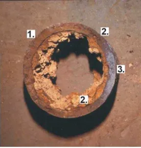
The examination should then consider the fracture surface itself. Initially the colour of any corrosion products along the fracture surface should be noted as well as their apparent depth. Changes in colour or depth should also be recorded. Past NRC research has indicated that many pipes fail in multiple stages5,7. The first episode of cracking may take place well before the second and/or final stage. This delay can produce significant differences in the chemistry and physical appearance of the corrosion products on the fracture surface between the stages. Figure 2 shows an example of the differences in the appearance of the fracture surface. Understanding this history may be important, as it can indicate whether a recent event (such as a pressure surge, local impact, excavation, or blasting) is solely responsible for the failure or if the problem had been developing for some time.
Figure 2. Pipe showing evidence of multi-stage failure. 1) Original cracking; 2) subsequent cracking; 3) intact metal broken in the laboratory.
It may also be possible to identify less obvious features. Graphitisation is generally not as obvious along the fracture surface as along cut metal. However, an area of corrosion product along the surface with a black, gray or greenish-black colour is a possible indicator of the presence of graphitisation. Manufacturing defects should also be
fracture to determine the origin of the fracture by examining the metal on the fracture surface. Cracks in the metal tend to form diverging lines of fracture as the object breaks. The arrow formed by two such cracks will point towards the origin of the failure. It may also be possible to determine something about the direction and nature of the failure from the dimples produced by the presence of graphite flakes in the pipe metal during the failure process. A direct tensile failure will tend to produce round dimples, while a crack that starts at a specific point and then propagates in one direction will produce concave dimples that point in the direction of the crack origin. Ewalds and Wanhill show a sketch that illustrates these differences10.
Finally, areas of the pipe that will be examined using other methods should be identified. These should include locations where fracture surface chemistry will be tested, places where metallographic samples will be taken, and regions where the possibility of the presence of graphitisation needs to be tested. Each of these tests are likely to require some damage to the sample, so care will need to be taken to preserve as much of the sample as possible.
Step 11 - Metallography
Metallography is the study of the microstructure of the metal in the pipe. Standard practices have been developed for the preparation of samples, classifying the graphite flakes in the cast iron and determining the size and nature of the grains in the metal. These practices should be followed by the consultant performing the failure analysis.
Examining the microstructure of the metal in the pipe is useful for two purposes. First, the manufacturing method used to make the pipe (pit casting, spin casting, spin casting to produce ductile iron, the use of metal or sand moulds in spin casting, etc.) affects the microstructure of the metal. Examination of the microstructure can therefore determine (or confirm) the method used to make the pipe. The examination can be particularly important if it is suspected that the water utility’s records are incorrect. Each manufacturing method produces a pipe with a characteristic type of metal microstructure. The differences in the microstructure produce different mechanical properties, with pit cast gray iron being weaker than spun cast gray iron, which is in turn weaker than ductile iron. The standards for the mechanical behaviour of the pipes also depend on the manufacturing method. Accurate knowledge of the method of manufacture is therefore essential in determining whether the pipe material meets the applicable standards.
The second purpose for performing metallography is to look for manufacturing induced problems that may weaken the pipe. The presence of iron phosphide networks can cause the material to be more brittle than would normally be the case, while other inclusions such as undissolved ferro-silicon can reduce the effective cross-section of the pipe wall. In addition, very slow cooling of the pipe metal can produce exceptionally large graphite flakes, which will also reduce the effective wall cross-section in addition to acting as points where cracks may start. All graphite flakes can cause this type of problem to some extent. The flakes act as crack formers, with the larger flakes being more problematic. The larger flake sizes in pit cast gray iron pipe are responsible for its
lower average mechanical strengths. However, cases have also been seen where exceptionally large flakes, with a 1-2 mm thickness, have been identified. Flakes of this size need to be treated as inclusions, rather than as part of the metal.
Step 12 – Looking for graphitisation
Graphitisation occurs when the iron oxide corrosion products react with the adjacent graphite to form a matrix of material that remains within the corrosion pit. Trace elements from the surrounding soil are also likely to be present. Recent NRC research suggests that rapid corrosion will tend to remove the iron in its entirety, leaving behind only graphite, which can be easily removed. However, slower corrosion processes likely allow time for the graphitisation products to form.
This type of corrosion presents particular problems for the failure analysis. Normal corrosion pitting is readily identified by visual examination. However, graphitisation pits can be very difficult to locate on gray cast iron pipes. Badly graphitised pipes can appear to be undamaged to a visual examination. This is particularly the case when the outside surface of pipe is being examined, but can also be a problem along fracture surfaces.
There are two approaches available to measure the extent of graphitisation in a failed pipe. The first is to identify such corroded areas using non-destructive evaluation (NDE) techniques. Ultrasonic depth gauges, eddy current systems and x-ray photography may be useful for this purpose. Ultrasonic systems measure the timing of sound reflections from interfaces between different materials within the object being examined. The time of the reflection can be converted into a value for the depth of the interface, which in this case would be the edge of the region of graphitisation. The major drawback with the ultrasonic gauge is that it may be susceptible to problems caused by the interface between the graphitisation and the intact metal. Ultrasound reflects most strongly from an abrupt interface between two different materials. A more diffuse interface that gradually changes from one material to another tends to scatter or transmit more of the beam, rather than causing a strong reflection. Graphitisation typically presents such a diffuse interface that identifying the echoes from the interface layer may be more difficult than would be the case for different types of corrosion processes.
Eddy current systems, which rely on differences between conductivity and magnetic permeability, should have no difficulty in detecting graphitised areas, which will have very much lower values of both properties compared to the metal in gray cast iron. However, they may be unable to accurately measure the depths of corrosion pits due to the interface layer and the rapid reduction in the strength of the eddy current signal that occurs with increasing distance from the metal surface. In either case, test samples should be provided for testing the technique against the material being investigated. Unlike ordinary test samples, which are often prepared by creating steps in the metal to duplicate different metal thicknesses, these test samples need contain graphitisation interfaces. One approach to preparing such test samples is to use other pipe samples that can be scanned and then examined through the sand blasting method described below.
The results from those tests can then be used to calibrate the results from the non-destructive examination of the fracture surface.
X-rays are probably the most accurate method of locating graphitisation. While this technique can be difficult to use in the field, pipe samples can easily be x-rayed in the laboratory to identify the presence of graphitised pits. The major drawback to this method is that it may be difficult to identify the depth of the pit unless x-ray photographs are taken at multiple angles through the sample. In addition, safety considerations must be borne in mind during the examination.
The alternative approach to NDE for identifying graphitisation pitting is to sandblast the pipe in the area of interest. Sandblasting will remove any corrosion, leaving behind the bare metal and making obvious where pitting has occurred. However, sandblasting is a very destructive method of investigating the pipe. Cleaning the surface of corrosion also removes much of the evidence of the failure. Sandblasting should therefore only be used if the removal of this material will not cause future problems for the analysis. It should be the last stage in any analysis. As noted earlier, it is also recommended that only half the fracture surface should be sandblasted.
Step 13 – Looking for manufacturing flaws on the pipe surfaces
Many of the types of manufacturing defects described earlier can also be found on either the inner or outer surfaces of the pipe. However, they may also be hidden by the coating of iron oxide that is left on the surface by the manufacturing process. These surfaces should be examined after any sandblasting has taken place to determine if any manufacturing defects are present. If no sandblasting is planned to examine the fracture surface for graphitisation, a large sample of the pipe wall near the fracture surface should be removed and sandblasted to check for surface defects.
Step 14 – Mechanical testing
Mechanical testing is essential in a failure analysis for this material. Multiple tests performed by NRC on samples taken from a single pipe have shown that gray cast iron has widely varying mechanical properties. It is therefore incorrect to assume that any given pipe will conform to the standards in prevalence at the time of manufacture or that a single sample will produce mechanical properties that are representative of the pipe as a whole. Given this degree of variability, twenty five to thirty samples are necessary to give a robust statistical picture of the pipe’s mechanical properties. In many cases it will not be possible to make that number of tests. However, as many tests as possible should be made given the constraints of financial resources, pipe material and on the analysis. Three tests is the absolute minimum that should be required, but the high likelihood of the results of the tests being unrepresentative should be understood. If the results of the testing appears likely to be unrepresentative due to a close grouping of the values in tests, further tests should be performed to check those results.
The applicability of the standards themselves also needs to be considered. In many cases the relevant question about mechanical properties in a failure analysis is
whether the material met the relevant standards. However, many of the standards for gray cast iron now appear to be inappropriate. The 1908 AWWA standard (7C1–1908)11 called for a tensile strength measurement based on testing cast iron bars, rather than pipe material. Pipes taken from the same molten metal as the test bars are likely to be weaker than the bar itself. The bars had less mass than a pipe and would therefore cool more quickly, promoting lower graphite flake size and a stronger material. They would also be less likely to have as wide a variation in mechanical properties as a pipe, due to their smaller size, and would have a significantly reduced chance of having significant porosity.
Later standards required burst testing, 4 point bending (Talbot) tests and ring tests12-14. Burst testing required capping sample pipes and pressurising them until they burst. These tests therefore not only duplicated a possible failure mode but examined the entire pipe with failure occuring at the weakest point. The burst test strengths therefore appear to be a reasonable value that current tensile or burst tests should surpass.
Ring modulus of rupture tests appear to be much more questionable. Accurate results from this method of testing are very dependent on the uniformity of the ring. Changes in mechanical properties, changes in wall thickness, the presence of corrosion or the presence of manufacturing defects may all cause the test results to be inaccurate. Since these defects are precisely the type of event that may cause a pipe failure, the usefulness of the test for failure analysis (or any analysis of in-service pipe) is very limited. In addition, there are no current standards supported by the American Society for Testing of Materials for ring tests on cast iron or other metal pipes. Finally, measurements have shown that there is no correlation between the results of ring tests and those of four point bending tests. These factors suggest that ring testing should not be used to evaluate mechanical properties.
In contrast, the accuracy of the four point bending test should not be affected by the presence of corrosion pits or manufacturing defects, provided their effect on the moment of inertia and location of the neutral axis is taken into account. Four point bending tests are also standard methods for measuring ultimate bending moment or the modulus of rupture. However, the results of the four point bending tests should also be expected to be highly variable. Multiple tests should be performed as is the case for the tensile tests.
Finally, it should also be noted that preliminary research at NRC has shown that the presence of corrosion pitting may reduce the mechanical strength of the pipe material11. If these results are confirmed, the usefulness of comparing the results of mechanical testing to previous standards will need to be re-evaluated.
Step 15 – Elemental Analysis
Examining the chemical elements found in the pipe metal, on the pipe surface or on a fracture surface is normally done to confirm the results of the test methods discussed in steps 10 to 14. Differences between the traces elements found on different parts of the
different lengths of time, confirming that a multiple stage failure took place. Testing for the presence of magnesium will indicate whether a pipe is ductile iron, while a significant phosphorus content can help to confirm that pipe has been embrittled by iron phosphide networks discussed in step 11.
Step 16 – Final steps for mechanical failures
The completed failure analysis should indicate whether corrosion pitting, graphitisation, or manufacturing defects contributed to the failure of the pipe. If desired, the water utility or its civil engineering consultant can then use the size of any identified pits or defects in combination with the mechanical strength of the pipe and the observed failure modes to determine the size of the loads that may have been responsible for the failure. The consultants may also recommend that one or more additional pipe samples be taken from pipes in the same line as the failed pipe. These additional samples can be used for the purposes of comparison in order to determine if the entire pipeline has the same problems identified during the failure analysis.
Step 17 – Corrosion failures
Evidence that corrosion caused or contributed to the failure may warrant an investigation by a corrosion expert. Localised corrosion cells, adverse soil chemistry, bacteria, and stray currents are all possible causes of corrosion. The soil samples collected at the time of the failure (Step 5) may help to identify the source of the corrosion. The corrosion engineer may recommend additional testing to determine the cause of the corrosion and its extent, including methods such as half-cell potential or linear polarization measurements, the collection of additional soil samples or NDE inspection of the pipe using the remote field effect to locate corrosion pitting.
Step 18 – Identifying other factors contributing to pipe failures
Corrosion pits and manufacturing defects have been responsible for most of the pipe failures investigated by NRC. However, other factors may also contribute to a pipe failure. These factors should be taken into consideration when determining the ultimate cause of the failure. It is particularly important that they be considered when it appears that the forces applied to the pipe were insufficient to cause the failure even when any pits or defects were taken into account. They include incorrect design of the pipeline system, incorrect installation of the system or changes in the magnitude of the loads on the pipe due to changes in its environment since installation. The former two factors do not necessarily imply a lack of due diligence on the part of the line designer or installer. In many cases subsequent research has shown that practices accepted in earlier times had the undesired effect of enhancing pipeline failures rather than preventing them. Perhaps the best example of this type of problem was the placing of cast iron pipe on wooden blocks to hold it above the trench floor. This practice was later recognised to concentrate loads on the pipe at the blocks rather than distribute them evenly along its length as would be the case of a pipe laid directly on a properly bedded trench floor.
Changes in the loads experienced by the pipe may also not be easy to predict. While the construction of a building near the pipeline or a highway above it may increase the loads on the line in readily predictable ways, it is also possible that ground movements can occur due to more distant events whose effect on the pipe’s integrity can not be readily predicted. In these cases the water utility needs to determine whether the forces applied to the pipe have been relieved by the failure or if the line is still at risk. The civil engineer investigating the forces applied to the pipe will also need to examine the information collected throughout the failure analysis, including the background information in step 6, in order to correctly determine the cause of the failure.
After the Failure Analysis
The failure analysis should give the water utility a determination of the cause of the failure. Based on this information, the utility must decide what further steps should be taken to prevent future failures on the same line. This decision will need to be based on a complex combination of factors, including estimated risk of further failures, consequences of those failures, available resources and other priorities for those resources. While knowledge of the cause of failure is an essential component for estimating the risk of future failures, the other factors in making the decision are beyond the scope of this paper.
Conclusions
The management of underground infrastructure such as water pipes is often assumed by those outside the industry to be simple in nature. In reality it is a very complex process that requires a diverse range of expertise. Failure analysis, with its requirement for metallurgical, civil and corrosion engineering work in addition to the knowledge of the water utility itself, illustrates this complexity. Despite the difficulties it can present, accurate failure analysis is an essential tool for investigating pipe failures. It is particularly important in large diameter failures where water utilities need to determine the cause of the failure as a first step towards preventing a repetition of the problem.
This paper has presented a step by step process for conducting a failure analysis on gray cast iron pipe. The text is not intended to be definitive, but rather to provide suggestions for the use of water utilities and their consultants when they are confronted with the need to conduct such an analysis. The emergency situation created by a large diameter failure often means that the information necessary to understand the cause of the failure is lost during the repairs to the damaged water main. Advance planning on how to acquire the necessary samples and information can help to ensure an accurate failure analysis and better decision making after the failure has been repaired.
References
1. Zamanzadeh, M., et. al., Analysis of Failures in Water Mains, Materials Protection, August, pp. 50 – 53, 1990.
2. De Rosa, P.J. and Parkinson, R.W., Corrosion of Ductile Iron Pipe, Report TR241, WRc Engineering, Water Research Centre, Swindon, United Kingdom, 1985.
3. Fitzgerald, J. H., Corrosion as a Primary Cause of Cast-Iron Main Breaks, Journal of the American Water Works Association, vol. 60., no. 8, p.882, 1968.
4. Romanoff, M., Exterior Corrosion of Cast-Iron Pipe, Journal of the American Water Works Association, vol. 56, no. 9, p. 1129, 1964.
5. Makar, J.M., A preliminary analysis of failures in grey cast iron water pipes, Engineering Failure Analysis 7, pp. 43-53, 2000.
6. Makar, J. M., Failure Analysis for Grey Cast Iron Water Pipes, AWWA Distribution Systems Symposium, September 19-22, Reno, Nevada, 1999.
7. Makar, J. M., Desnoyers, R., McDonald, S.E., Failure Modes and Mechanisms in Gray Cast Iron Pipes, to be presented at 2001 International Conference on Underground Infrastructure Research, Waterloo, Ontario, Canada, June 10-13, 2001.
8. Kirmeyer, G. J.,Richards, W., and Smith, C.D., An Assessment of Water Distribution Systems and Associated Research Needs, American Water Works Association Research Foundation, Denver, 1994
9. Rajani, B., Zhan, C. and Kuraoka, S., Pipe-soil interaction analysis of jointed water mains., Canadian Geotechnical Journal, Vol. 33, No. 3., 1996.
10. Ewalds, H.L. and Wanhill, R.J.H, Fracture Mechanics, Edward Arnold (Publishers) Ltd., London, pg. 236, 1984.
11. AWWA (American Water Works Association). Standard Specifications for Cast Iron Water Pipe and Special Castings, 7C.1–1908, AWWA, Denver, Colorado, 1908.
12. American Standards Association, American Standard Specifications for Pit Cast Pipe for Water and Other Liquids, A21.2 –1939, AWWA, Denver, Colorado, 1939.
13. American Standards Association, 1953. American Standard Specifications for cast-iron pipe centrifugally cast in metal molds, for water or other liquids. A21.6-1953/AWWA C106-53, AWWA, Denver, Colorado, 1953.
14. American Standards Association, 1953. American Standard Specifications for cast iron pipe centrifugally cast in sand-lined olds for water and other liquids, A21.8-1953/AWWA C108-53, AWWA, Denver, Colorado, 1953.