HAL Id: hal-00433411
https://hal.archives-ouvertes.fr/hal-00433411
Submitted on 18 Feb 2010
HAL is a multi-disciplinary open access
archive for the deposit and dissemination of
sci-entific research documents, whether they are
pub-lished or not. The documents may come from
teaching and research institutions in France or
abroad, or from public or private research centers.
L’archive ouverte pluridisciplinaire HAL, est
destinée au dépôt et à la diffusion de documents
scientifiques de niveau recherche, publiés ou non,
émanant des établissements d’enseignement et de
recherche français ou étrangers, des laboratoires
publics ou privés.
High performance mode adapters based on segmented
SPE:LiNbO3 waveguides
Davide Castaldini, Paolo Bassi, Pierre Aschieri, Sorin Tascu, Marc de Micheli,
Pascal Baldi
To cite this version:
Davide Castaldini, Paolo Bassi, Pierre Aschieri, Sorin Tascu, Marc de Micheli, et al.. High performance
mode adapters based on segmented SPE:LiNbO3 waveguides. Optics Express, Optical Society of
America - OSA Publishing, 2009, 17 (20), pp.OPTICS EXPRESS 17868. �hal-00433411�
High performance mode adapters based on
segmented SPE:LiNbO
3
waveguides
Davide Castaldini,1,2 Paolo Bassi,1
Pierre Aschieri,2 Sorin Tascu,2,3 Marc De Micheli 2 and Pascal Baldi 2,*
1 Dipartimento di Elettronica Informatica e Sistemistica, University of Bologna, Viale del Risorgimento 2, I 40136 Bologna, Italy
2
Laboratoire de Physique de la Matière Condensée, University of Nice—Sophia Antipolis, CNRS, 06108 Nice, Cedex 2, France
3Alexandru Ioan Cuza University of Iasi, Faculty of Physics, Solid State Physics Group, Bulevardul Carol I, Nr. 11, Cod 700506, Iasi, Romania
Abstract: We propose a new mode adapter which allows more efficient
launching of the optical power selectively in the fundamental mode of a multimode waveguide. Theoretical and experimental results confirm that such a mode adapter increases the performances in terms of coupling efficiency, coupling tolerances and transmitted power with respect to previously proposed solutions. Proof of principle of device operation is obtained with a simple Coupled Mode Theory model. Experimental results are obtained at a wavelength of 840 nm in Lithium Niobate Soft Proton Exchanged waveguides and agree very well with theoretical predictions.
References and links
1. S. K. Das, “Modal noise due to short-wavelength (780-900-nm) transmission in single-mode fibers optimized for 1300 nm,” Appl. Opt. 27, 552-556 (1988).
2. Z. Haas and M. A. Santoro, “A mode-filtering scheme for improvement of the bandwidth-distance product in multimode fiber systems,” IEEE J. Lightwave Technol. 11, 1125-1131 (1993).
3. L. B. Soldano and E. C. M. Pennings, “Optical multi-mode interference devices based on self-imaging: principles and applications,” IEEE J. Lightwave Technol. 13, 615-627 (1995).
4. A. Kumar, S. Ghadirli and K. Thyagarajan, “Performance of a dual-mode-single-mode waveguide coupler as a modal filter,” Appl. Opt. 31, 5092-5095 (1992).
5. M. Kobayashi, H. Terui and K. Egashira, “Optical-mode filters using coupling between two nonidentical waveguides (ET),” Appl. Opt. 17, 486-490 (1978).
6. A. Kumar, U. K. Das, R. K. Varshney and I. C. Goyal, “Design of a mode filter consisting of two dual-mode highly elliptical-core fibers,” IEEE J. Lightwave Technol. 8, 34-38 (1990).
7. H. Han and J. J. Coleman, “Lateral-mode discrimination in ridge waveguides by misaligned total internal reflection mirrors,” IEEE Photon. Technol. Lett. 7, 715-717 (1995).
8. H. Yajima, “Dielectric bypass waveguide mode order converter,” IEEE J. Quantum Electron. QE-15, 482-487 (1979).
9. W. K. Burns and A. F. Milton, “An analytic solution for mode coupling in optical waveguide branches,” IEEE J. Quantum Electron. QE-16, 446-454 (1980).
10. C. W. Lee and M. K. Chin, “Design of lateral-modes filter based on high-index contrast waveguide,” Opt. Comm. 253, 87-94 (2005).
11. Z. Weissman and A. Hardy, “Modes of periodically segmented waveguides,” IEEE J. Lightwave Technol. 11, 1831-1838 (1993)
12. M. H. Chou, M. A. Arbore and M. M. Fejer, “Adiabatically tapered periodic segmentation of channel waveguides for mode-size transformation and fundamental mode excitation,” Opt. Lett. 21, 794-796 (1996).
13. D. Ortega, R. M. De La Rue, J. S. Aitchison, “Cutoff wavelength of periodically segmented waveguides in Ti:LiNbO3,” IEEE J. Lightwave Technol 16, 284-291 (1998).
14. A. Yariv, “Coupled-mode theory for guided-wave optics,” IEEE J. Quantum Electron. QE-9, 919-933 (1973).
15. D. D. Stancil, “Kronig-Penney model for periodically segmented waveguides,” Appl. Opt. 35, 4767-4771 (1996).
16. D. Castaldini, P. Bassi, S. Tascu, P. Aschieri, M. P. De Micheli, and P. Baldi, “Soft-Proton-Exchange Tapers for Low Insertion-Loss LiNbO3 Devices,” IEEE J. Lightwave Technol. 25, 1588-1593 (2007). 17. S. G. Johnson, P. Bienstman, M. A. Skorobogatiy, M. Ibanescu, E. Lidorikis and J. D. Joannopoulos,
“Adiabatic theorem and continuous coupled-mode theory for efficient taper transitions in photonic crystals,” Phys. Rev. E 66, 066608 (2002).
18. D. Marcuse, Light Transmission Optics, 2nd Ed., Van Nostrand, (1982).
1. Introduction
In many Integrated Optics (IO) devices, such as frequency converters, couplers, Mach-Zehnder interferometers, and ring resonators, single-mode regime is required for controllable operation of the desired function. Higher order modes are responsible for instabilities and degraded performances. In ring resonators, for instance, the existence of different modes, with different propagation constants, affects the total transmission. In coupler and Mach-Zehnder devices, different modes have different coupling lengths which increase crosstalk and reduce both the coupling efficiency and the signal-to-noise ratio [1, 2]. Unfortunately, the single-mode condition cannot always be fulfilled. For example, in χ(2) based frequency converters,
one of the three interacting wavelengths is much shorter that the others. This means that the waveguide supporting guided modes at all the wavelengths is multimode at the shorter one.
Many kinds of IO mode filters have been proposed to overcome this problem: multimode interferometers [3], asymmetric couplers [4-6], total internal reflection mirrors [7], asymmetric Y junctions [8, 9] and laterally tapered waveguides [10]. They all are difficult to fabricate as they have small fabrication tolerances and significantly increase the size of the device. Moreover, in many cases, they cannot filter out the power launched in in-depth higher order modes. The use of waveguides with longitudinal periodic changes of refractive index, the so called Segmented Waveguides (SWG) [11], has also been proposed to overcome these issues [12]. These devices consist in an initial section with a SWG able to guide only one mode, whatever input field is coupled to it, followed by a tapered SWG allowing adiabatic coupling of this mode to the fundamental one of a multimode Continuous Waveguide (CWG). The drawback of this configuration is the poor coupling tolerance in the single-mode SWG.
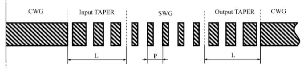
In this paper we demonstrate both theoretically and experimentally a new type of mode adapter based on SWG with the same positive features of that proposed in [12] but with increased coupling tolerances and efficiency. The device schematic is shown in Fig. 1.
Fig. 1. Scheme of the fabricated mode filter. Dashed regions: higher refractive index regions.
The novel part of the device is the initial one. It includes the CWG and the input taper. The CGW is multimode and makes coupling to the external source less critical. The input taper is designed not simply to filter out the higher order modes, as in [12], but, as explained later, to transfer as much as possible power from the higher order modes to the fundamental one in the SWG, to increase the overall guided power. The final part of the device is standard. The SWG, operating in single mode regime at the desired wavelength by a proper choice of its duty cycle (DC, defined as the size ratio between the higher refractive index segment and the period P) [13], filters the remaining higher index modes out of the device. The output taper adiabatically transforms the only guided mode to the fundamental one of the multimode CWG belonging to the IO device. The expected net result, confirmed experimentally, is an increase
of the overall device performances. The best performance is expected when the input taper transfers all the incoming power to the fundamental mode of the SWG and the output taper does not excite the higher order modes of the output CWG. The two tapers operate in quite different regimes. The former taper has multiple input modes. It should then maximize power transfer from higher order modes to the fundamental one as, at its end, higher order modes are cut off. The latter taper operates with a single exciting mode and is a standard adiabatic taper, transforming the fundamental mode of the SWG to that of the multimode CWG, without exciting any higher order mode of the CWG itself. Though the two tapers can be designed independently, in this first attempt to demonstrate the device operation, we have considered tapers with the same characteristics, leaving their separate optimization for a next stage.
The proof of principle of device operation will be provided in the next section, using the Coupled Mode Theory (CMT) [14] and the equivalent waveguide model [15]. Then we will present experimental results, obtained for segmented waveguide mode adapters designed with a 3D BPM code and fabricated on z-cut LiNbO3 substrate by the Soft Proton Exchange
Technique [16]. Experimental results fit very well with theoretical predictions, confirming both the theoretical hypotheses and the improved performances of the device.
2. Device modeling
As in [12], the filter working principle is based on the fact that the modes of the tapered SWG sections can couple to each other, while they do not in the uniform SWG and CWG sections being mutually orthogonal [17]. We consider only the lowest and the first higher order modes, with amplitudes A0 and A1 respectively, as they can be assumed to dominate the multi-mode
propagation. In each taper, modes are assumed to obey the local CMT equations [14]:
(1) where Δβ(z) is now the propagation constant difference between the two modes and κ(z) is the coupling coefficient, both unknown and varying along the longitudinal coordinate z. This model can anyway be easily extended to include more interacting modes, if necessary.
The value of Δβ(z) can be calculated with a good approximation considering the local normal modes of the equivalent waveguides of each section of the SWG taper. Figure 2 shows, as an example, the effective index evolution at λ = 840 nm for a cubic taper, i.e. a taper for which the DC evolves proportionally to z3, from DC = 0.3 to DC = 1, with L = 2000 µm and P = 25 µm. At the beginning of the taper only the fundamental mode can propagate. Then, at z ≈ 0.2 mm, the second one starts propagate. For larger values of z, the propagation constant difference Δβ of the two modes increases: for example, at z = 0.33 mm, Δβ = 0.89x10⁴ rad/m, while at z = 2 mm, Δβ = 1.64x10⁴ rad/m. But, since Δβ/β remains small throughout the taper, the CMT can anyway be used. The behavior shown in Fig. 1 corresponds to that of an output taper. The input one has symmetrical characteristics.
The value of κ(z) is more difficult to be determined as it depends both on the varying DC and on structure imperfections, such as surface roughness, unavoidable whatever fabrication technology is used. To try an estimate, we considered first an infinitely long SWG, where mode coupling is only due to waveguide imperfections. This leads to an “asymptotic” value of κ that we denote by κ∞ . As, for small imperfections of the waveguide core, only the first order
term of the Fourier series approximating the index distribution plays a role, it is reasonable to assume a sinusoidal approximation of the waveguide roughness [18]. A precise determination of such a roughness would require sophisticated techniques which were not available and were anyway beyond the scope of this paper. For the following simulations, we then simply assumed, always after [18], that the perturbation of our SWG equals 1% of the waveguide
width. The coupling coefficient turns out to be κ∞ = 4000 m
-1. When the SWGs are tapered,
this value increases as the varying DC increases perturbations. So, κ(z) will be assumed as the sum of κ∞ and a function depending on the DC change rate (cubic in our case).
Fig. 2. Effective index of the fundamental (solid line) and higher order (dashed line) modes in propagation through a cubic taper. The mode transformation is obtained with DC varying from 0.3 to 1 and L = 0.2 mm.
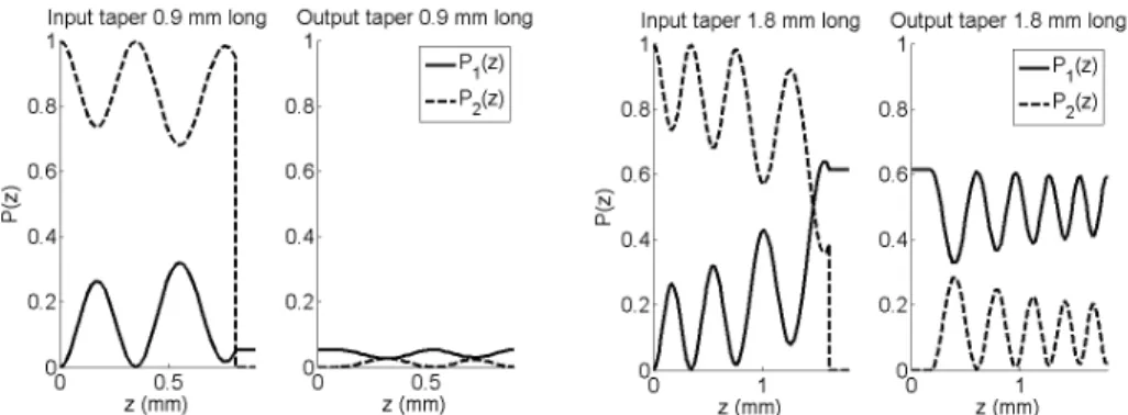
Equations (1) must then be solved for the whole device of Fig. 1. Both tapers convert back and forth the energy among the propagating modes. In any case, at the end of the input taper, only the fundamental mode remains guided. So, besides filtering the higher order modes, the input taper should allow good power transfer to the fundamental one. On turn, the output taper should change the fundamental mode shape without introducing significant coupling to higher order modes. The device performances can then be optimized designing the two tapers independently. Figure 3 shows results obtained in the worst case of pure higher order mode excitation for two possible devices. The two halves of the figure refer to structures where, for simplicity, both tapers are assumed with the same length: 0.9 mm (left) and 1.8 mm (right) respectively. Fundamental and higher order mode longitudinal evolutions are shown by solid and dashed lines. As one can see, even for pure higher order mode excitation, there are device lengths which are expected to efficiently convert power to the fundamental mode.
Fig. 3. Power evolution of the fundamental (P1, solid line) and higher order (P2, dashed lines) in the input and output tapers with L = 0.9 mm (left) and 1.8 mm (right) when only the higher order mode is initially present.
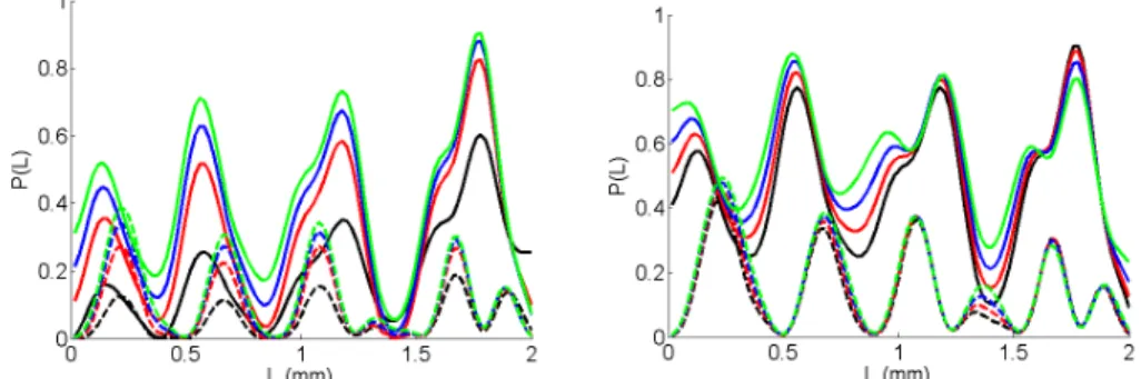
In real cases, however, the input optical field excites the two IO waveguide modes with the same phase but with a-priori unknown amplitude. Figure 4 shows then the mode power distributions at the device output for taper lengths up to 2 mm, for different excitation conditions in cases where the higher order mode is significantly present. In particular, the fundamental mode launched power ranges from 0% to 70%. Larger values are not reported also as they would correspond to cases where the device would be useless. As one can see,
there are conditions in which the fundamental mode has larger power at the output than at the input. Such conditions do not depend so much on excitation conditions but mostly on taper length. Longer tapers tend to reduce the presence of the higher order mode, though this positive effect can be balanced by larger propagation losses. These results show that combining two tapered SWGs creates a mode transformer and not simply a mode filter.
Fig. 4. Calculated normalized fundamental (solid line) and higher order (dashed line) mode intensities at the output of the mode filter as a function of the taper lengths L for κ∞ = 4000 m-1 and for different ratios in the input power distribution. In the left part of the figure: black, red, blue, green curves refer respectively to 0%, 10%, 20% and 30% of the total input power launched in the fundamental mode. In the right part, the colors refer to 40%, 50%, 60% and 70% of the total input power launched in the fundamental mode.
3. Experimental results
To check experimentally the just explained results and the possible benefits of the proposed mode adapter to relax coupling conditions, some devices have been fabricated using the SPE technique on LiNbO3 substrate, as described in [16]. Input and output tapers have the same
length for simplicity. Their DC varies proportionally to z3, from DC = 0.3 to 1 with period P = 25 µm. Should the operating principle be demonstrated, better performances could be obtained with separate taper optimizations, as said before. To completely eliminate the mode at cutoff, a 5 mm long SWG is inserted between the two tapers. The sample has also CWGs and SWGs (without tapers) to check the multimodality and the filter effect respectively.
The experimental setup adopted to characterize the properties of our mode adapters uses a diode laser source (λ = 840 nm). The incident beam is end fire coupled to the sample with a microscope objective mounted on a piezoelectric stage. Accurate control of the objective position allows modifying the excitation conditions of the waveguides. The output signal is collected by a second microscope objective and then split by a semi-reflecting mirror. Part is sent to an infrared camera (Hamamatsu) and the rest is sent to a detector to evaluate the transmitted power. The camera allows visualizing in real time on a monitor the shape of the near field and evaluating whether higher order modes are present or not. The characterization procedure determines the signal power at the output of the sample as a function of the input objective position and records, at the same time, the output field pattern.
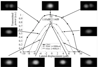
Figure 5 shows the transmitted normalized power for a simple CWG (continuous line) and two waveguides with mode adapters, with input and output taper lengths LA = 0.6 mm
(dashed line) and LB = 1.6 mm (dotted line). Results are obtained moving the input
microscope objective horizontally to simulate different coupling conditions. For the CWG alone, coupling is critical: for a lateral displacement of 4 µm only the higher order mode is excited. This does not occur when the mode filter is used, as shown by the dotted and dashed curves, corresponding to devices with tapers. In both cases, only the fundamental mode is present at a displacement of 4 µm, confirming that the mode filter guarantees less critical coupling conditions. But these results also confirm the effects related to the taper length, for example the rather counter intuitive result foreseen by simulations: the longer device works better. When the lateral displacement of the exciting beam is 6 µm, in fact, the fundamental
mode is practically negligible in the device with taper length LA = 0.6 mm. But, at the same
lateral displacement, the filter with taper length LB = 1.6 mm allows to measure an output
power increased by about 30%. This effect is possible only as mode conversion occurs in the device. Moreover, one can also note that the so called device additional losses, related to the difference between the power transmitted by the considered device and the simple straight waveguide, are lower when the longer taper is used. For the filter taper length LA = 0.6 mm,
additional losses are in fact 1.6 dB, while for LB = 1.6 mm they are 1.05 dB. As suggested
before, the 0.55 dB difference between these two values is due to different radiation and propagation losses occurring in the two tapers which have different lengths. These results confirm that longer tapers may have better performances and that the price to pay in terms of losses to improve the coupling tolerances is quite affordable for standard IO components.
Fig. 5. Transmitted power measured as a function of the lateral displacement of the input objective for a continuous and two filtered WGs with taper length LA = 0.6 mm (dashed line) and LB = 1.6 mm (dotted line). Camera images confirm the single-mode behavior of the filtered waveguides. Symbols represent measured values; lines are for visual aid only.
4. Conclusions
In conclusion, we have demonstrated that SWG tapers can be used not only for adiabatic mode transformation, but also to transfer energy from a higher order mode to the fundamental one. This can be used to improve coupling efficiency between an integrated waveguide and external components such as optical fibers or sources. The standard deviation for single mode coupling varies from 3.55 µm (taper A) to 5.79 µm (taper B). As shown in Fig. 5, these values correspond to operating conditions in which, without the proposed device, the coupled mode is basically the higher order and not the fundamental one. Note also that these results have been obtained for input and output SWG tapers of the same length, which is not the optimized configuration: even better performances can then be expected. The main limitation of the present structure is that its behavior still strongly depends on the coupling coefficient κ∞,
which comes from technological imperfections, and is difficult to control. Future work shall then concentrate on this issue by introducing a well controlled sinusoidal modulation of the refractive index to better control and maximize the energy transfer.
Acknowledgments
D. Castaldini is grateful to the UIF, French Italian University, for providing the Vinci scholarship which allowed his participation to this work.
Funding of the European Community through the 6th PCRD IP "SECOQC" and by the
Italian Ministry of Education, University and Research (MIUR) is gratefully acknowledged. Authors are grateful to Sebastien Tanzilli and Anna Guagliumi for helpful discussions.