HAL Id: hal-02368690
https://hal.archives-ouvertes.fr/hal-02368690
Submitted on 18 Nov 2019
HAL is a multi-disciplinary open access
archive for the deposit and dissemination of
sci-entific research documents, whether they are
pub-lished or not. The documents may come from
teaching and research institutions in France or
abroad, or from public or private research centers.
L’archive ouverte pluridisciplinaire HAL, est
destinée au dépôt et à la diffusion de documents
scientifiques de niveau recherche, publiés ou non,
émanant des établissements d’enseignement et de
recherche français ou étrangers, des laboratoires
publics ou privés.
Alain Billard, Francis Maury, Pascal Aubry, Fanny Balbaud-Célérier, Benjamin Bernard, et al..
Emerging processes for metallurgical coatings and thin films. Comptes Rendus Physique, Centre
Mersenne, 2018, 19 (8), pp.755-768. �10.1016/j.crhy.2018.10.005�. �hal-02368690�
OATAO is an open access repository that collects the work of Toulouse
researchers and makes it freely available over the web where possible
Any correspondence concerning this service should be sent
to the repository administrator: [email protected]
This is a Publisher’s version published in:
http://oatao.univ-toulouse.fr/21940
To cite this version:
Billard, Alain and Maury, Francis
and Aubry, Pascal and Balbaud-Célérier,
Fanny and Bernard, Benjamin and Lomello, Fernando and Maskrot, Hicham
and Meillot, Erick and Michau, Alexandre and Schuster, Frédéric Emerging
processes for metallurgical coatings and thin films. (2018) Comptes Rendus
Physique, 19 (8). 755-768. ISSN 1631-0705
Alain Billard
a,
Francis Maury
b,
Pascal Aubry
c,
Fanny Balbaud-Célérier
c,
Benjamin Bernard
d,
Fernando Lomello
c,
Hicham Maskrot
c,
Erick Meillot
d,
Alexandre Michau
c,
Frédéric Schuster
e,
∗
,
1aFEMTO-STInstitute(UMRCNRS6174),UniversitéBourgogne–Franche-Comté,UTBM,2,placeLucien-Tharradin,25200Montbéliardcedex,
France
bCIRIMAT,CNRS/INPT/UPS,4,alléeÉmile-Monso,31030Toulouse,France
cDEN–Serviced’étudesanalytiquesetderéactivitédessurfaces,CEA,UniversitéParis-Saclay,91191Gif-sur-Yvette,France dDAM–Départementdesmatériaux,CEALeRipault,37260Monts,France
eCross-CuttingprogramonMaterialsandProcessesSkills,CEA,UniversitéParis-Saclay,91191Gif-sur-Yvette,France
a
r
t
i
c
l
e
i
n
f
o
a
b
s
t
r
a
c
t
Articlehistory:
Availableonline6November2018 Keywords:
Magnetronsputtering Chemicalvapordeposition Spraying Lasercladding Mots-clés : Pulvérisationmagnétron Dépôtchimique Projection Rechargementlaser
Innovation inthin-filmdepositionprocesses,thermalspraying andcladding technologies mostlyrelyonevolutionsoftheirpreviousiteration.Alongwithotherexamples,fivecase studiesofemergingelaborationprocessesformetallurgicalcoatingsaredescribedcoupled with their applications. In the frame of the lifetime extension of components exposed to aggressive media ortheir functionalization, thisarticle depicts all the developments of the detailed processes. Physical vapor deposition(PVD) of coatings with exceptional properties is possible thanks to sources generating highly ionized metallic vapors. The controloftheaverageenergyperincidentspeciesand particularlymetallicionsstrongly influencesthe characteristics ofthedeposited layerobtained, for example,withHiPIMS (HighPowerImpulseMagnetron Sputtering).WhilePVDtechniquesare mainlydirective regarding thegrowthofthecoating,chemicalvapor deposition(CVD) processesmanage
to homogeneously coat complex 3D shapes. The use of specific precursors in DLI–
MOCVD (DirectLiquidInjection– MetalOrganicCVD),carefullyselectedfromthe whole metalorganic chemistry, allows one to efficiently treat heat-sensitive substrates and broadenstheir application range. Thethird detailed example ofemerging technologyis suspensionplasmaspraying(SPS).Projectionofvarioussolutionscontainingnanoparticles leadstothegrowthofunusualmorphologiesandmicrostructuresandtothegenerationof porous coatingswith multi-scaledporosity. Onthe otherhand, cold-sprayusesmetallic
powders with higher granulometry and does not modify them during the deposition
process.Asaresult,high-purityanddensematerialsaredepositedwithpropertiessimilar tothoseofwroughtmaterials.Whereascold-sprayissuitableonlyforductilemetals,laser cladding canbeappliedtoceramics, polymersand ofcoursemetals.Lasercladding isa key technologyforadvanced metallurgicalengineeringand alloydevelopment duetoits capabilityforfunctionallygradedmaterialsproductionandcombinatorialsynthesis.
©2018Académiedessciences.PublishedbyElsevierMassonSAS.Thisisanopenaccess articleundertheCCBY-NC-NDlicense (http://creativecommons.org/licenses/by-nc-nd/4.0/).
*
Correspondingauthor.E-mailaddresses:[email protected](A. Billard),[email protected](F. Schuster).
1 Coordinator.
https://doi.org/10.1016/j.crhy.2018.10.005
1631-0705/©2018Académiedessciences.PublishedbyElsevierMassonSAS.ThisisanopenaccessarticleundertheCCBY-NC-NDlicense (http://creativecommons.org/licenses/by-nc-nd/4.0/).
r
é
s
u
m
é
L’innovationdanslesprocédés dedépôtde couchesmincesouépaissesetlaprojection thermiquerepose principalementsur lesévolutionsde leursversions précédentes.Cinq étudesde casde procédés émergents d’élaboration de revêtementsmétallurgiques avec leursapplicationssontproposées.Lesdéveloppementsdesprocédéssontdétaillésdansun contexted’améliorationdeladuréedeviedecomposantsexposésàdesmilieuxagressifs. Ainsi, des revêtements aux propriétés exceptionnelles sont obtenus par des procédés
de dépôt physique en phase vapeur (PVD) grâce à des sources de vapeur métallique
fortementionisée.Les propriétésdes couchessont contrôlablespar exemple en HiPIMS (pulvérisation magnétron par impulsions deforte puissance)via l’énergiemoyenne des ions métalliques. Alors que les techniques PVD sont plutôt directives, les procédés de dépôtchimiqueen phasevapeur (CVD)parviennent àrevêtir uniformémentdesformes complexes.L’utilisation en DLI-MOCVD (Direct LiquidInjection – MetalOrganicCVD) de précurseurssoigneusementsélectionnésauseindelachimieorganométalliquepermetde traiterefficacement dessubstrats thermosensiblespour élargir le domaine d’application de ces revêtements. Le troisième exemple de technologie émergente est la projection plasmadesuspensions.Cesdernièrescontenantdesnanoparticules,leurprojectionmène àlacroissance de structures inhabituelles etàdes revêtementsàporosité multiple.La projectionà froidutilisequant àelle despoudres métalliques avec desgranulométries supérieures. Celles-ci ne subissant pas de transformations pendant leur projection, des matériaux denses et de haute pureté sont déposés avec des propriétés comparables à cellesdematériauxcorroyés.Alorsquelaprojectionàfroidconvientauxmétauxductiles, lesrevêtementslaserpeuventêtreappliquésauxcéramiques,polymèresetbiensûraux métaux.Cettetechnologieestessentiellepouruneingénieriemétallurgiqueavancéeetle développementdenouveauxalliagesenraisondesacapacitéàproduiredesmatériauxà gradientetàutiliserlasynthèsecombinatoire.
©2018Académiedessciences.PublishedbyElsevierMassonSAS.Thisisanopenaccess articleundertheCCBY-NC-NDlicense (http://creativecommons.org/licenses/by-nc-nd/4.0/).
1. Introduction
Metallurgicalcoatingsandthinfilmshavebeendeveloped inthefield ofhigh-performancemetallurgyforavery long time. Theyoftenrely onthe implementationofquite oldprocesses, butemergingtechnologiesare regularlyinvolved. As surface functionalizationstepsareincreasinglyintegratedfromthebeginningintheconceptionandlifecycleofa compo-nent, itis thenpossible toproduce efficientarchitecturescapableof addressingcomplex andextremeenvironments.The coatingsgenerallyoperateundercombinedstressessuchasmechanicalloadingwithcorrosionorirradiationinadditionto oxidation orcorrosion.Thus, themain driverforthedevelopment ofsurface engineeringinthe metallurgyfield isabout improvingcomponentlifetimes.
For mostapplications, the coating design hasto be done on the basis ofprecise specifications when the elaboration method is dictated by a certain number ofscientific, technological, economic,and environmental criteria. Materials effi-ciency, especially whenitcomes totheuse ofcriticalmetalsforexample,aswell astherecyclability ofscarceresources canalsoinsomecasesbecomeamajorcriterion.
Thispaperdoesnotaimatmakingacomprehensivelistofsurfaceengineeringprocessesformetallurgybut,onthe con-trary,toillustratewithafewwell-targetedexamplestheinnovationintermsofmaterialsandprocessesthroughindustrial applications. Thelatter isoftentheresult oftechnological progressmadeby existingprocesses usually knownfora long time.
Surfacetreatmentprocessesfallintofourmaincategories:thin-filmdepositionprocesseswith,inparticular,PVD (Phys-ical Vapor Deposition) andCVD (Chemical Vapor Deposition) aswell as their hybridized technologies, thermalspraying processes in the broad sense (plasma high velocity oxy-fuel, cold spray...) leading to thick coatings,diffusion processes (among thempackcementationandderivativeprocesses,implementationofpowderslurries,liquidmetals
. . .
),and weld-ing processes.Conversionprocessesandpost-treatmentsalsoneedtobeconsidered.Theycanconferormodifyparticular propertiestotreatedsurfaces(recrystallizationofextremesurfaceforexample,bylaserorelectronbeamtreatment).Thepurposeofthisarticleistoillustratepotentialvectorsofprocessinnovationthroughseveralexamples,successively PVD, CVD, thermal spraying, and more specifically plasma spraying and cold spraying, and finally laser cladding, which belongs towelding processes.The complementarity betweentheseprocesses isillustrated inFig. 1interms ofsubstrate temperature, ranging from0◦C to 1000◦C, andcoating thickness, ranging from0.1 μm to 10mm. Regarding PVD tech-nologies,the mainrouteforinnovationisthedevelopment ofnewpowersuppliesleading tometallic vaporswithahigh ionizationratethatresultsinspecificproperties,forinstancethecontrolofmicrostructureandinterfaces.InthecaseofCVD, theappropriatechoiceofmetalorganicprecursorsallowsusfirsttolowerthedepositiontemperatures,makingtheprocess compatiblewithheat-sensitivesubstrates,andsecond toaccesstheentirediversityofchemistryintermsofcompositions
Fig. 1. Coating process comparison (reproduced from [1]).
andcompounds.Finally,whendealingwiththermalsprayingtechnologies,itisveryclearthattheaccesstoinnovativeand on-demandpowdersconstitutesoneofthemainvectorsoftechnologicalrupture.Itis,forinstance,thecasewiththe possi-bilitytoproducegradientcoatingsorviaacontrolledimplementationofnanopowdersusethroughtheformofsuspensions oraggregates.
2. Innovationinthinfilmstechnologies
In the first part of the review, two innovative vapor deposition technologies are presented, i.e. the HiPIMS and the DLI–MOCVD. Since they are quite different interms of physical chemistry, they are described separately in two distinct sections.
2.1. High-power impulse magnetron sputtering for more efficient PVD
Ifthephenomenon ofsputteringwas highlightedinthemiddleofthe19thcenturyby W.R.Grove,itisinthesecond halfofthe20thcentury,andmoreparticularlyfromtheworkofP.Sigmundduringthe1960s[2],thattheunderstandingof thephysicalandphysicochemicalphenomena involvedandthetechnologicalprogressledtotheindustrialdevelopmentof sputtering.Themicrostructureandpropertiesofthefilmsbeingrelatedtotheaverageenergyperincidentspecies(Fig.1), manystudieswereconductedfromthe1980sonhighlyionizeddischarges(i-PVD)likelytoleadtothesputteringofmetal ions.Duringthe1990s,theInduced CoupledPlasma(ICP) technique involvingtheadditionofaradio frequencypolarized antennaandtheexploitationofelectron–cyclotronresonance(ECR)fromacavitysubmittedtomicrowaveradiationallowed onetopartiallyionize thesputteredmetal vapor.However,itisonlyfromtheworkofW.M.Posadowskietal.[3] onthe effectoftheincreaseofpowerdissipatedonthetargetthatV.Kouznetzovetal.[4] publishedthefirstworkonhigh-power impulsemagnetron sputtering(HiPIMS) in1999, pavingthewayforinnovative applicationsinthefield ofphysicalvapor depositionprocesses.
Diodesputteringconsistsinestablishinganelectricdischargeinararefiedatmosphere(1Pa)ofraregas,generallyargon, byapplyingapotentialdifference(1kV)betweenthetarget,consistingofthematerialattheoriginofthecoating,andthe wallsof thereactor connectedto themass.The Ar+ ions arethen attractedby the negative electricfield applied tothe targetandtheirimpactcausesthesputteringofmetalatomsbyballisticeffect.Themetalvaporthuscreatedcondenseson thesubstratetoformacoating.Thesynthesisofdensecoatingsrequirestoreducethedepositionpressuretoaround0.1 Pa, which isincompatible withthe possibilityof carryingout a diode discharge dueto a mean free path ofelectrons close to that of thetarget-to-substrate distance (10 cm).Maintaining a stablelow-pressure discharge then requires concentric magnetsplacedbehindthetarget,generatingfield linesthatclosewithinthegasphase,trappingtheelectrons,whichcan thencreateionizingshocksintheimmediatevicinityofthegasphase.Thisiscalledmagnetronsputtering.Theintroduction ofachemically activegassimultaneouslywithargonallows thesynthesisofceramic coatingsfrommetal targets,butthe instability ofthe discharge requiresthe implementationof closed-loopcontrol systems toallow the highratedeposition of stoichiometricceramic coatings.High Power Impulse Magnetron Sputtering(HiPIMS) technologyconsists insupplying thetarget withpulsesof10to 200 μs atfrequenciesofthe orderof100to500Hz.The instantaneous powerdissipated during thepulsescanreachabout1MW,whichcorresponds tocurrentsofafew thousandamperesforabias voltageof 600to 1000 V.However, the average powerremains close to afew kW in orderto preserve the integrity of thetarget. Suchconditionsmakeitpossibletoionizethesputteredmetalvaporaccordingtotwomainmechanisms:byimpactofthe electronsofthedischargeorbyPenningionization,producedbythecollisionwiththeexcitedmetastableargonatoms.
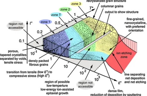
Fig. 2. Schematicmorphologyofcoatingsasafunctionofthegeneralizedtemperature(T *),whichconsidersthetemperatureshiftcausedbythepotential energyoftheparticlesarrivingonthesurface,andnormalizedenergyofimpingingspecies(E*),whichdescribesthedisplacementandheatingeffects causedbythekineticenergyofthebombardingparticles,seeRef.[5] foranexplanation(reproducedfrom[5]).
•
excellentadhesionofthecoatingsobtainedforlimitedetchingtimesofthesurfacetobecoated,•
a microstructure and a densityof the layers associated witha level of adjustableinternal stressesthrough the bias voltageofthesubstrates,whichmakesitpossibletoperfectlymanagetheaverageenergyperincidentspecies,•
greaterhomogeneityofcoatingsdepositedonsurfacesofcomplexgeometry,•
thepossibilityofsynthesizingstoichiometriclayersforreactivegasflowrateslowerthanthecriticalflowrateatwhich thisinstabilityoccurs,•
thepossibilityofcrystallizingphases,includingmetastableones,attemperatureslowerthanthosedefinedby thermo-dynamicequilibriumand/orobtainedbyconventionalmagnetronsputteringmethods.However, itis necessarytoemphasize thepreponderant effectofthemagneticconfigurationof themagnetron onthe performanceoftheHiPIMSprocess,particularlyintermsofdepositionrateandpropensitytomaintainasufficientionization rateofthemetalvaporinthevicinityofthesubstratetobecoated.
ThecontroloftheaverageincidentionenergyassociatedwithHiPIMStechnologyallowstheoptimizationofthe proper-tiesofthinfilmsinmanyareascomparedtothesamecoatingsdepositedbyconventionalmethods,orevenbythemethod ofvacuumcathodicarcdepositioninthefield ofhardandultra-hardcoating.AspresentedinFig.2,HiPIMSallowsoneto accesstofilm-growthregimessuchinzonesuchasinzone3.
Inthefieldoftransparentconductiveoxides,theimprovementoftheconductivityofn-typecoatingssuchasZnO:Alis believedto berelatedtoepitaxialeffects.Inthe aeronauticalfield,increasedperformanceshavealso beenobservedwith regard toerosion by sandorwater ofAlTiN coatings comparedto the samecoatings depositedby alternative processes. Finally,exceptionalperformance hasbeenobtainedwithrespecttotheprotectionofnuclearfuelcladdingwithchromium coatings,bothundernominalconditionsandunderloss-of-coolantaccidentconditions(LOCA)[6].Fortheselasttwo appli-cations,theperformancesobtainedareassociatedwithexcellentadhesionofthelayersandcompactnessthatconventional oralternativemethodsdonotachieve.
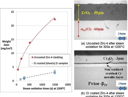
Concerning theprotective coatings on Zr-basedcladding, an enhanced high-temperature steamcorrosion resistance is measured after300sinthe 1000–1200◦CrangeifcomparedwiththeuncoatedZr-basedcladdingaspresentedinFig.3. Moreover, foranextendoxidationtimesup to6000sunderthe maximumLOCA’s(Lost-of-coolantaccident)temperature (1200◦C),ithasbeenobservedthatthecladsegmentisabletoresisttothefinalwaterquenchingdowntoroom tempera-ture.
TheupscalingprocessonFramatome’sM5®claddingsforafurtherindustrializationiscurrentlyinprogress[5].Thelatter isthesolutionchosenbyFramatomeintheframeoftheenhancedaccidenttolerantfuel(EATF)competition[7,8].
The HiPIMS technologyallowsone toimprovethe coatings’adherenceandthemicrostructure’s densityon zirconium-basedsubstrates; itwasdemonstratedthatCr–Si–Nnanocompositessystemspresentapromisingbehavior whentheyare submitted tohigh-temperatureoxidation(Fig.4)[10].Thistypeofnanocompositescoatingswillleadtoanincreaseofthe performancesofclassicalchromiumcoatings[11].
Moreover,otherinterestingHiPIMSproductsareTi–Si–Nnanocompositeshardcoatingsthatpresentanenhanced oxida-tionresistanceathightemperatures[12].ThesecoatingsareusuallyprocessedbyHiPIMScoupledandDC-pulsedmagnetron
Fig. 3. Comparisonbetweentherespectivehightemperaturesteamoxidationbehaviorsat1200◦Cofuncoatedvs.CrcoatedZircaloy-4samples(reproduced from[9]).
Fig. 4. Phase content evolution of Cr–Si–N HiPMS PVD coatings as a function of the oxidation temperature (reproduced from [10]).
sputtering(PDCMS).Thehybridizationofthesetechniquespermitsanaccuratecontrolofthesiliconcontentincoating,thus allowingonetoaddanoptimalsiliconcontentwhichallowsonetoretainthemechanicalpropertiesunderextreme condi-tions.
AmongthepropertiesrequiredforthedevelopmentofcoatingsfortheenhancedATF,agoodbehaviorunderirradiation innominalconditionsisrequired.TheworkachievedbyMamourSal[13] on thestudyofthebehaviorunderion irradia-tionofCr–Tamultilayeredsystemsprovidesinteresting andpromisinganswers.Indeed,inthiscontext,Cr–Tananolayered systemswitharespectiveperiodof15nmand50nmwereirradiatedintheJannusacceleratorwiththeaimofsimulating their behaviorwhenthey are submittedtoneutron irradiation.Thefirst resultsshowthat multilayeredstructure remains intact,evenafteraradiationdoseof250dpa2(Fig.5).
Furthermore,regardingtheresponsetoheavy ionsandheliumimplantation,themostsignificantresultsshowthatthe Cr–Tainterfacesare goodtrapsforhelium,thepost-implantationdiffusionisvery limitedin systemswitha highdensity of interfaces.Cr–Ta systems with a periodof 15 nm allow 20% of helium accommodation, which induces a self-healing behavior of thesecoatings under irradiation. The Cr–Ta interfaces act as defecttraps that allow a recoveryefficiency of above80%forthe15-nmperiodsystems.
As showninthe previous examples,HiPIMS is aprocessing routethat opens manypossibilities interms ofadvanced metallurgy. Recently, MAX phases have been synthesized by HiPIMS in one single step [14,15]. These types ofcoatings
Fig. 5. Cr–Ta nanolayeredsystemaftera250-dpairradiationdose:(A)transmissionelectronmicroscopy and(B)energydispersive X-rayspectrometry micrographs(reproducedfrom[13]).
present an enhanced erosion resistance. Because of their high temperature resistance and self-healing properties, some researchersarefocusingthestudiesonMAXphasesaspotentialcandidatesforthenextgenerationofEATF[16].
Finally, HiPIMS recentlypermitted to depositnew metallic compounds such as high-entropy alloys (HEAs). Some re-searchershaveshownthatthesematerials havehighstrength,excellentcorrosionresistance,goodthermalstability,anda superiorwearresistance[17].
HiPIMS is an innovative technology that is attracting considerable academic interest because ofits abilityto manage the average energy per incident species that conditions the properties of thinfilms. This enthusiasm is also shared by generators manufacturers who have multiplied over the last decade. Its tricky implementation,in particular because of the considerable influence of the magnetic configuration of the magnetron sources on the performance of the process, andthecostofthegeneratorsmeanthattheindustrialdevelopmentsremainconfidential.Nevertheless,thistechnologyis approachingamaturitythatshouldleadtoanamplificationofindustrialapplicationsoverthenextdecade.
2.2. DLI–MOCVD to take advantage of the diversity and richness of organometallic chemistry
TheChemicalVaporDeposition(CVD)processeshavemanyindustrialapplications,inparticularinthefieldofcuttingand forming toolsdueto(i) their highproductivity,(ii)thewide rangeofadvancedcoatingsthat can bedeposited (carbides, nitrides, oxides
. . .
),(iii) theperformance ofthesecoatings optimizedthanks to specific compositions, microstructures or architectures (multilayers, nanocomposites, compositional gradient. . .
), and(iv)the goodconformal coverage on complex shapesandgeometries. Inthefield offunctionalthinfilms, CVDisalsoan industrialtechnique, forinstanceforepitaxial growthofsemiconductorsinmicroelectronicsorfordepositingfunctionallayersinsolarcellfabricationandglassindustry. For decades, CVD processes were operating at high temperatures because they were based on the chemistry of the halides,whichconsiderablyslowedtheirdevelopment.Theincreasingdemandforhighly diversifiedandhigh-performance coatingsleadstoprocessdevelopmentsforwhichscale-up,lowdepositiontemperature,anduniformthicknessare perma-nentandstringentrequirements.Inthiscontext,newprocessesareemerging.The familyofCVDprocessesisbased onthegeneration andtransport ofareactive vapor phasethat uponits decom-position inaprocess chamberproduces thegrowthofacoating onthe surfaceto becoveredby heterogeneouschemical reactions.Theenergyrequiredfortheactivationofboththegasphaseandtheheterogeneousdecompositioncanbemainly thermal, photonicorelectricdischarge(plasma). Plasma-enhancedCVDprocessesareundergoingimportantdevelopments forsurfaceengineering, butthey arenotdiscussedhere.Weonlycite,asanexampleinmechanicalengineering,diamond coatingsthatareindustriallydepositedbymicrowaveplasmaCVDaswearresistantcoatings[18].
Onceovercominglow-temperatureandscale-upconstraints,thermalCVDprocessescanachieve challengesthatarenot feasible ordifficult to demonstrate by other techniques.Therefore, they can be implemented into manufacturing in-line or roll-to-roll CVD reactors to deposit protective coatings (BN, TaC
. . .
) on substrates moving at constant speed [19] or for continuousdeposition offunctional layersatan industrial levelasgraphene[20] andphotovoltaic Si[21]. Also, mass productionofceramiccompositematerialsisperformedbylow-pressureCVDinporousbodies,namelybychemical vapor infiltration(CVI)[22].A recent challenge is the development of a process capable of uniformly covering the inner wall of long tubes with a protective coating a few microns thick. Atomic-layer deposition (ALD) belongs to the familyof CVD, and was initially developed principally for manufacturing metal oxide functional thin films. ALD is extremelyconformal and it has been recentlyusedforthedepositionofHfO2 ontheinteriorsurfaceinacomplexcoolingcircuitforcorrosionmitigationbythe cooling fluid [23].However, ALD still suffersfromvery low growthratesto bea viableprocess fordevelopingprotective coatings.
engineeringachievableinmetalorganicchemistryfordesigningsuitableprecursors,manyofthembeingnowcommercially available.
InitiallyDLI–MOCVDhasbeendevelopedandhasgrownrapidlyforthegrowthoffunctionaloxidethinfilmsforoptical andelectronic devices [24]. Foroxide deposition, carboncontamination ofthe films originatingboth from theprecursor andthe organic solventwas preventedby adding an O2 partial pressure, whichinvolves both combustion andpyrolysis reactions.ThepioneeringworkonDLI–MOCVDofcarbides[25],nitrides[26] andmetals[26] frombis(arene)Mprecursors, whereMisatransitionmetalintheoxidationstatezero(Cr,Mo,W,V. . . ),hasrevealedagreatpotentialforapplicationsas metallurgicalprotectivecoatings.FurtherworkonSiC[28] andHfChasconfirmedtheinterestofthisprocess,forinstance toproducenanostructuredmultilayercoatingsbyreadilycontrollingthegasphase[26].
ThemaindisadvantagesoftheDLI–MOCVDprocessresultfromtheuseofhighlyreactiveandsometimestoxicprecursors, andfromtheimplementationofacomplexchemistrythatcanbedifficulttocontrol,inparticularforupscalingtheprocess. However,botharecentexperimentalresultsdemonstratingthepossibilityofclosed-looprecyclingofeffluents[29] and amodelingapproach[30] contributetotheburgeoningindustrializationpotentialofthisDLI–MOCVDprocess.Furthermore, obtaining increasedperformance ofadvancedcoatingssometimesrequirestherealizationofspecificnanostructuresor ar-chitecturessuch as multilayersor nanocomposites.As a result, complexcoatings sometimeshave tobe made by several techniques,andit isobviousthat thereisaconsiderableinterestforhybridprocessesimplementedinasingle deposition chamber.TheDLI–MOCVDmethod,justlikeitsparentMOCVD technique,hasagoodpotentialforhybridization.For exam-ple,III-nitridetunneljunctionswerefabricatedby ahybridMOCVD/MBE(MolecularBeamEpitaxy)process combinedina single chamber [31].Also, plasma-enhancedDLI–MOCVDwas usedforthegrowthofphase changematerials (GeTe)[32], andanovelhybridMOCVD/ALDreactorhasbeenimplementedtofabricateSnOx/TiO2 multilayers[33].
The Cr–C–Nsystem allows aremarkable flexibility.It isboth a modelfor analogousM–C–Nsystems (M
=
Cr, V,Nb, Mo) where similar precursors exist, and a basic system for many metallurgical protective coatings. Bis(arene)chromium precursors decompositionthrough DLI–MOCVDprocessresults inthegrowthof amorphousa-CrC
x coatings between623and773K[29]. Theseorganometallic moleculeshavea sandwichstructure withacenterCratom characterizedbya zero oxidation state.Consequently, noCr(VI) derivative isinvolved inthisREACH(the European regulationaboutRegistration, Evaluation,AuthorizationandrestrictionofCHemicals)compatibleprocess.Theadditionofacarboninhibitorleadstothe depositionofcrystallizedmetallicCr[27] whilecubicCrN(andCr2(C, N)intermediatenitride)canbegrownbycontrolling aNH3 partialpressure[26]. NanostructuredCrC/CrN multilayercoatingscanbe readilyobtainedasshowninFig.6a.The Cr(0)chemistry implementedinthisprocess allows aloop-recyclingofeffluents untiltheir entiredecomposition,leading toaconversionyieldcloseto100%,whichsignificantlydecreaseboththeeconomicandtheenvironmentalimpactsofthe process[28].
The dense and amorphous a-CrCx coatings exhibit a glassy-like microstructure without grain and grain boundaries.
They have a high hardness (20 to 25 GPa) and a good abrasive wear resistance. Thermally stable up to about 873 K, they crystallizedabovethistemperaturetoformchromiumcarbides.Si-doping (2at. %)increasesthetemperatureofthis amorphous-to-crystallizedstructuraltransformationto1023K.Finally,theexcellent high-temperatureoxidationresistance of
a-CrC
xcoatingsmakesthemanefficientbarriertoprotecttheinner-surfaceofZr-basednuclearfuelcladdingsinaccidentconditions(Fig.6b)[34].
Numericalmodelingandmulti-scalesimulationoftheprocessareessentialapproachesforupscaling.ADLI–MOCVDpilot iscurrentlycapableofinternallyprotectsabundleof1-m-longfuelcladdingsegmentswithauniformlythick
a-CrC
x coatingof severalmicrometers, as shownin Fig. 1c.Many evaluations specific to nuclear applications are currently in progress. By continuing the coupling between modeling and experimentation, the scaling progresses towards its final extent, i.e. full-lengthnuclearcladdingsof4m.ThiswouldbeafirsttransferofaDLI–MOCVDprocessinthemetallurgyfield.
Fig. 6. Scanningelectronmicroscope(SEM)cross-section(a)ofaCrCx/CrNmultilayercoatinggrownbyDLI–MOCVDconstitutedof30layerswithaperiod
of53nm,(b)ofaprotectivea-CrCxcoatingafteroxidationathightemperatureasdescribedin[18],and(c)computationalsimulationofadepositionina
bundleof16cladsegments1minlength,validatingthedesignofthegas-phasedistributor.
Fig. 7. Illustration of a nanoparticles suspension sprayed by SPS (courtesy of CEA).
3. Innovationinthermalsprayingandcladdingtechnologies
While thefirstpartofthisreview dealtwithprocessesbelongingtothinfilms depositiontechniques,thesecond part presentsthreetechnologiescapableofcoatingcomponentswiththickerlayers.Theyconsistinsuspensionplasmaspraying, coldspray,andfinallylasercladding.
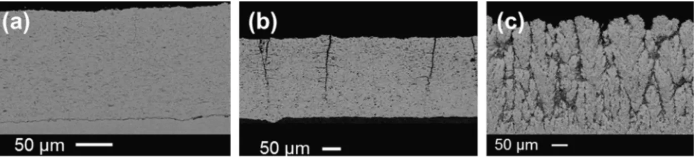
3.1. Suspension Plasma Spraying (SPS) for the best use of nanomaterials
The SuspensionPlasmaSprayprocess wasdevelopedfromthepioneer studiesonliquidinjectionthroughflame(early 1970s) andplasma (1900s) fornanopowder synthesis [35,36]. If the principle remains closeto the initial developments, liquid feedstock thermalspray processes andparticularlysuspension plasma spraying (SPS) are widely studiedsince the 2000sforcoatingproductionduetotheirvariousapplications,asdescribedbythefollowingreviews[35–37].
SuspensionPlasmaSprayingconsistsintheinjectionofthinparticles(
<
5 μmandmostgenerallybetween0.1and1 μm) throughaplasmajet.(SeeFig.7.)MostoftheplasmaguntechnologiesusedfortheSPSprocessarebasedontheionization ofplasma gases(argon,helium,nitrogenoramixtureofthem) byadirectcurrent(DC)discharge betweenacathodeand an anodenozzle,allowingaplasmajetathightemperature(8000–14 000K)andvelocityranges(800–2200m/s)[35].The injectionofsuch asthinparticles requiresacarriermedium heavierthanconventional carriergases usedinAtmospheric Plasma Spraying (APS).Here, solid particles aredispersed in a liquid,usedas acarrier medium. Thissuspension is then injectedthroughtheplasmajetusingacalibratedinjector(usually0.1–0.5mm).Theliquidisfragmentedindropletsbefore its vaporization.In ordertoreduce the energyconsumptionduring liquidvaporization, alcohol-basedsuspensionscanbe used,provoking combustionwithair.FreeparticlesarethenmoltenandacceleratedsimilarlywiththeAPSprocess before flattening onto the substrate. Theuse ofthinner particlesthan forAPS imposes lower standoffdistances (30–50 mm) to prevent anin-flightre-solidificationofmoltennanoparticles[5].Thelow sizeoftheparticlesusedfortheSPS process in-ducesnewcoatingbuild-upmechanismsleadingtounusualmicrostructuresforthermalspray-likecolumnarmicrostructure [38].•
SPScancreatethinfilmcoatings(afewmicrometers);•
SPScansprayvariouscompositionsofmaterialsbyusingasolutionofprecursorsorpowdersinsuspension. Ontheotherhand,theSuspensionPlasmaSprayingprocesspresentsalsosomedrawbacks:•
thedepositionrateissignificantlylowerthanconventionalplasmasprayprocesses(2–3timeslower);•
the lower standoff distance could induce an overheating of the coatedcomponent part, requiringa specific cooling system(forexample,cryogeniccooling), andalsocouldlimit themovementofthe plasmagunin frontofacomplex coatedcomponent.TheabilityofSPS toperformporous coating(usually10–30%) withmulti-scaledporosity appearstobe interestingfor energyandbiomedicalapplications.Forexample,SPS coatingscouldimprovethe performancesofSolid OxygenFuelCell (SOFC)asanelectrolyteandenhancetheirbiocompatibilityformedicalprostheses.
Intheaeronauticfield, SPSisclosetoitsindustrialexpansionwithSPSthermalbarriercoatings(TBCs)and/or SPS en-vironmentalbarriercoatings(EBCs)usedfortheprotectionofhotsectionpartsofgasturbineengines.Indeed,theunusual columnarstructureobtainedbySPSisparticularlyinterestingfortheprotectionofNickel-basedsuperalloyturbineblades andvanes. The mainaeronautic OEMs(Original Equipment Manufacturers)develop TBCs usingSPS for improved proper-ties(thermal lifetime, thermalinsulation)atlow costcompared tothe standardcoatings performedbyEB-PVD (Electron Beam-PhysicalVaporDeposition).
SuspensionPlasmaSprayingisclosetobecomeamaturecoatingprocess,mainlysupportedbyaeronauticaldevelopments on TBC. Indeed, this process allows various coating morphologies and can be easily added to industrial thermal spray facilities. These technical developments are supported by plasma spray manufacturers withplasma gun and suspension deliverysystemsaswellasthermalspraypowdermanufacturerswithcommercialsuspensionsreadytouse.
3.2. Cold Spray for dense ductile coatings
TheColdSpray(CS)processwasdevelopedinthemid-1980sbyscientistsfromtheInstituteofTheoreticalandApplied Mechanics oftheSiberianBranch ofthe RussianAcademyofSciences (ITAM ofRAS)inNovosibirsk,Russia[39].Thegoal was to deposita large range ofductile materials onto differentsubstrates inan economic way.The principle is still the same,whilethedeviceshavebeenimprovedduring thesenearly fortyyears.Readerswhowanttogofurthercanreferto thefollowingreferences[38,40,41].
ColdSprayisakineticsprayprocess,utilizingsupersonicjetsofcompressedgastoaccelerateparticlestohighvelocities. Fig.9showsthetypicalprinciple.
Issuingfrom thepowder feedstock, the particles(typically 5–50 μm)are injected in ahigh-pressurelow-temperature gas flow (nitrogen,helium or mixturefrom 0.4– low-pressure device – to5 MPa – high-pressuredevice – from300K to1400K)beforetraveling toade Lavaltype nozzle.Atthenozzleexit,thesolid ductileparticles,inmotionatvelocities between300and1500m/s,plasticallydeformonimpactwiththesubstrate,andconsolidatetocreateacoating.However,it impliesthatparticlevelocitiesatimpactarehigherthanaso-calledcriticalvelocity(seeFig.10),whichdependsonparticle material,size,andmorphology.
TheColdSpray(CS)processisofhighinterestduetothefollowingadvantages:
•
CSiswellsuitedfordepositionofalargerangeofmaterials(temperature-sensitive,oxygen-sensitiveandphase-sensitive materials)becauseofthelowdepositiontemperature;•
CSofmetalsgenerallyenhancesfatigueresistancebecauseofthemicro“shot-peening”effect,withgenerally compres-siveresidualstressesintheresultantdeposits;Fig. 9. Principle of Cold Spray, including a de Laval nozzle type.
Fig. 10. Behavior of impacting Cu particles upon substrate depending on the velocity.
•
metal CS deposits havemicrostructures withhighdegreesofconsolidation similar towrought alloysdueto intrinsic high-energylow-temperaturefeatures;•
CSdepositspresenthigherdensityandreducedpresenceofoxidephases;•
CShassignificantlygreatdepositionefficiency(DE),dependingonthematerialproperties;•
CS presentssmallspraybeamandsooffers moreprecisecontrol overthe areaofdeposition ontothe substrate(less needformaskingoftheas-sprayedpart);•
CSgenerallyincreasesthepossibilityofdissimilarmaterialsjoiningbecauseoflessheatinputintothesubstrate,which makesthesubstratematerialtobeoflesserimportance;•
ahighvelocityofcoatingbuildingcanbeobtained(upto1mm/pass);•
astrongbondingbetweenthemetalmatrixandthedispersant. Ontheotherhand,theColdSprayprocesspresentssomedrawbacks:•
depending onthebothmaterials, powderandsubstrate,thiscouplecanpresentahighlevelofresidual stresses(due toshotpeening),whichrequiresheattreatmentfortensiondecreasing;•
allthematerialscannotbedepositedduetoatoohighhardness,forexample,leadingtoatoohighcriticalvelocityand soaweakDE.E. Lugscheider [42] has emphasized the broadvariety of feedstock materials usedin cold spray andso the potential applicationssuccessfullyused:
– againstcorrosionandwear;
– forrepair,especiallymagnesiumparts; – forelectromagneticinterferenceshielding;
– fordemandingelectric,electronic,orthermalapplicationsaswellasefficientdepositionofsolderingorbrazingalloys; – forconductingstructuresonnonmetalcompositelayers.
For some years, the Cold Spray process also appears as an attractive opportunity for free standing near-shape parts by additive manufacturing [43] (because of the highdeposition efficiency, highcoating-building velocity, and numerical increasingpossibilitiesbetweendesigncomputerandrobot).
ColdSprayprocessesare emergingtechnologiesthat addressshortcomingsoftheother thermalsprayprocesses.Their main interests lie in their ability to spray high-purity materials, with no modification of the oxide content of sprayed metallic powders, andto make coatings with properties closeto those of wrought materials and localized deposits for repairpurposes.
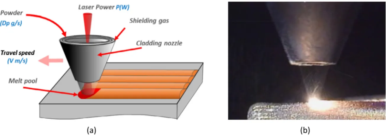
Fig. 11. Illustration of the laser cladding principle (a) and picture of the cladding nozzle and (b) of the melt pool during operation.
However, such processescan onlyspray ductilematerials (metals, alloys, cermets).Since 2006, newinvestigations are devotedtoceramiccoatingscoldsprayed,achievedbysprayingagglomeratednanometer-sizedparticles.Thebestresultsare obtainedwithheliumasthespraygas,buttheincreasingcostofdepositionleadstosprayinaclosedvessel(forrecycling 90–95%ofthegasused).Thatiswhydevelopmentsarealsocarriedoutwithnitrogenastheworkinggas.
3.3. Laser cladding for combinatorial synthesis and graded materials
Lasercladdingwas developedatthe endof1970salong withthedevelopment oflasertechnologiesformaterial pro-cessingapplications.Withtheincreaseinlaserbeamcapacityenablingthemeltingofmaterials,thisprocesswasoptimized andusedtogeneratethickanddensedepositsofheterogeneousmaterialonasubstratesurface.Theresultingmaterialsare characterized by improvedphysical propertiesoftheir surfaces aswear,corrosionresistance orthermal barriers.Initially developedforcoatingapplications,lasercladdingwasextendedtomanufacture3Dshapes.
Thelasercladdingprocessconsistsofasprayofaconcentratedpowderflowunderalaserbeamonasubstratesurface. The melting of the powder and ofthe upper part of the substratesurface layer generates a melt pool. The progressive movement of the cladding nozzle results in the production of a solidified layer of additional material with a typical thickness from100 μm to some millimeters (see Fig. 11). Instead of powder, a fillerwire can also be used asmaterial provision.
Lasercladdinghasseveraladvantages:
•
finecontrolofthemeltingzoneandassociatedfusionprocesses,thankstothecapabilityofcontrollingenergy deposi-tion;•
largetreatedzoneallowingthinorthickdepositsthankstothevariationofthelaserbeamproperties;•
productionofmaterialswithveryfinemicrostructureduetofastsolidification;•
productionofdenseandheterogeneousmaterials;•
largerangeandtypeofmaterials(metals,ceramics[44] andpolymers).In the framework of cladding processes, laser cladding can be compared to other welding type processes as Plasma Transferred Arc Welding (PTAW), where the fusion energy is provided by an electric arc. If PTAW is a commonlyused process formanufacturing thickcoatings,therangeofthetreatedzoneislimitedcomparedto laser.Moreover, thePTAW allowsonlyhighdepositionratesfromabout1mmlayerthicknessandinduces deepdilutionzones. Finally,theobtained microstructureistypicallycoarserthanthemicrostructuresynthetizedbylaserprocess.
Thankstothehighversatilityofthelaserfusionenergy,alargerangeofapplicationscanbeenvisaged:
•
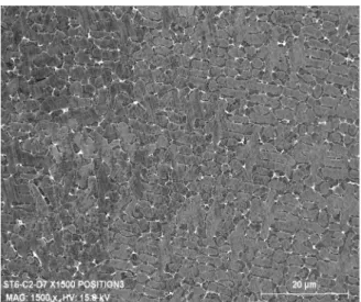
depositionofhardfacingmaterialsforwearresistance(Fig.12)[45,46].Usinglasercladdingleadstogeneratecoating ofhighquality:controlledgeometryanddilution,thinmicrostructure,highhardness. . .
•
depositionofnear-shapegeometries(Fig.13).Laseradditivemanufacturingallowsthindepositionanditscapabilityto build accuratestructuresisadaptedto repairconditions(optimizationoftherepair time,thermalcyclesandinduced stress. . .
);•
possibilityofmixingseveralmaterials withvariouschemicalcompositions.Thedifferentpowdersaredirectlyinjected fromdifferentpowderfeedersandaremixedintothenozzlebeforesimultaneousmelting.Thisspecificprocessallows manufacturingmetallic-matrixcompositematerials;•
possibilityofacontinuousvariationofthechemicalcompositionofthedepositbyvaryingthefeedingrateofdifferent powders.Thistechniquecanbeusedtoproducegradedmaterialsin3D[48].Thisisparticularlyinterestingfordifficult boundingsituations, as adaptionof differentialdilation coefficientsbetween the substrateandthe coating materialsFig. 12. SEM observations of thin Stellite 6 microstructure obtained by laser cladding.
Fig. 13. Laseradditivemanufacturingisusedtobuildthethinwallsforthelatticeonanaerospacecomponent.Thelatticeisfilledwithaceramictoform asealagainstthebladethatrubsagainstit(reproducedfrom[47],courtesyofRolls-Royce).
or metallurgical incompatibilities (direct synthesis of a specific intermediate layer). By extension, the laser cladding processenablestheproductionofmetallicmaterialsbyusingacombinatorialmethodology.Theevolutionofthe com-positionbycontrollingthepowderflowsofdifferentpowderfeedersallowsgeneratingalargerangeofalloysinasingle experimentalcampaign.
Although thisprocess hasbeen developedfor about40 yearsand isnow a widely used process to produce material surface withimproved physicalproperties,lasercladding hasto beconsidered asa keyopportunity inthe researchfield dedicated to materials engineering. The adaptation of thisprocess to therecent development performed in the metallic additivemanufacturingdomainallowsconsideringalargerangeofpotentialapplicationsasrepairand3Dgradedmaterials.
4. Concludingremarks
Surfaceengineeringisemergingasastrategicdisciplineinthefieldofhigh-performancemetallurgy.Originallydeveloped toprotect componentsagainst theaggressiveenvironmentswheretheywork,itismoreandmoreoftenusedto function-alize themby activatingtheir surface regardingspecific physicalor chemicalphenomena. Photocatalytic,anti-bacterial or anti-biofoulingsurfacesaredeveloped,forexample,respectivelyinthefieldsofairandwaterdepollutionandmarine ener-gies. Surfaceengineeringalsoprovideslow-costmetalsubstrateswithhighaddedvaluelikemetallicsurfacescoveredwith thin-filmphotovoltaiccellsforsolarthermalapplications.
The few examples of emerging technologies and applications presented in this article demonstrate that through the constant evolution of surface treatment processes, it is possible to propose innovative solutions, including for the most stringent industrialsectorsofhighperformance metallurgy.The development ofHiPIMS PVDprocesses, ortheintegrated
istheswiftdevelopment of3D printingtechnologiesallowingone togeneratetopologicallyoptimizedcomponents,often withcomplexorporousalveolararchitecturesthatmustbeprotectedfromaggressivemediaormustbesurface functional-ized.Thefinishingtechnologiesofadditive manufacturingpartsmustalsobedevelopedtominimizetheimpactofallthe defectsappearingduringthe3Dprintingstep.Itisforinstancethecaseofthedevelopmentofelectrolyticplasmapolishing technologies.
Finally,newmethodologiesandnumericaltoolsenablemuch fasterdevelopment offunctionalcoatingsanddeposition processes. High-throughput approaches such as combinatorial synthesis and artificial intelligence contribution have just startedtorapidlyoptimizecomplexprocesses,thanksinparticulartotheuseofneuralnetworks.
References
[1] O.Metko,Anintroductiontothermalspray,https://www.oerlikon.com/ecomaXL/files/metco/oerlikon_BRO-0005.6_Thermal_Spray_Brochure_EN.pdf,July 2016.
[2]P.Sigmund,Theoryofsputtering.I.Sputteringyieldofamorphousandpolycrystallinetargets,Phys.Rev.184(1969)384–416.
[3]W.M.Posadowski,Z.Radzimski,Sustainedself-sputteringusingadirectcurrentmagnetronsource,J.Vac.Sci.Technol.A11(1993)2980–2984. [4]V.Kouznetsov,K.Macák,J.M.Schneider,U.Helmersson,I.Petrov,Anovelpulsedmagnetronsputtertechniqueutilizingveryhightargetpowerdensities,
Surf.Coat.Technol.122(1999)290–293.
[5]A.Anders,Astructurezonediagramincludingplasma-baseddepositionandionetching,ThinSolidFilms518(2010)4087–4090.
[6] Nuclearfuelcladdings,productionmethodthereofandusesofsameagainstoxidation/hydriding,USPatentApplicationUS20170287578A1,2014. [7]J.Bischoff,C.Delafoy,C.Vauglin,P.Barberis,C.Roubeyrie,D.Perche,D.Duthoo,F.Schuster,J.C.Brachet,E.W.Schweitzer,K.Nimishakavi,AREVANP’s
enhancedaccident-tolerantfueldevelopments:focusonCr-coatedM5cladding,Nucl.Eng.Technol.50(2018)223–228. [8] Framatome:thenextevolutionofnuclearfuelwebsite,https://nextevolutionfuel.com/.
[9]J.-C.Brachet,M.LeSaux,M.LeFlem,S.Urvoy,E.Rouesne,T.Guilbert,C.Cobac,F.Lahogue,J.Rousselot,M.Tupin,P.Billaud,C.Hossepied,F.Schuster,F. Lomello,A.Billard,G.Velisa,E.Monsifrot,J.Bischoff,A.Amabard,On-goingstudiesatCEAonchromiumcoatedzirconiumbasednuclearfuelcladdings forenhancedaccidenttolerantLWRsfuel,in:ProceedingsofTopFuel2015,EuropeanNuclearSociety,Zurich,Switzerland,2015,pp. 13–19. [10]A.Ferrec,Dépôtetcaractérisationdemétauxetdenitruresàbasedechromeparpulvérisationmagnétronpulsée(HiPIMS),Ph.D.Thesis,Université
deNantes,Nantes,2013.
[11]J.-C.Brachet,M.LeSaux,V.Lezaud-Chaillioux,M.Dumerval,Q.Houmaire,F.Lomello,F.Schuster,E.Monsifrot,J.Bischoff,E.Pouillier,Behaviorunder LOCAconditionsofenhancedaccidenttolerantchromiumcoatedzircaloy-4claddings,in:ProceedingsofTopFuel2016,Boise,ID,USA,2016. [12]M.ArabpourYazdi,F.Lomello,J.Wang,F.Sanchette,Z.Dong,T.White,Y.Wouters,F.Schuster,A.Billard,PropertiesofTiSiNcoatingsdepositedby
hybridHiPIMSandpulsed-DCmagnetronco-sputtering,Vacuum109(2014)43–51.
[13]M.Loyer-Prost,C.Cabet,M.Sall,A.Billard,P.H.Jouneau,H.Khodja,RadiationtoleranceofCr–Tamultilayercoatings,in:PosterattheNuMat:Nuclear MaterialsConference,Montpellier,France,2016.
[14]H.Rueß,M.toBaben,S.Mráz,L.Shang,P.Polcik,S.Kolozsvári,M.Hans,D.Primetzhofer,J.M.Schneider,HPPMSdepositionfromcompositetargets: effectoftwoordersofmagnitudetargetpowerdensitychangesonthecompositionsputteredCr–Al–Cthinfilms,Vacuum145(2017)285–289. [15]D.Eicher,A.Schlieter,C.Leyens,S.Shang,S.Shayestehaminzadeh,J.M.Schneider,SolidparticleerosionbehaviorofnanolamiatedCr2AlCfilms,Wear
402–403(2018)187–195.
[16]M.Ougier,F.Lomello,F.Schuster,A.Michau,E.Monsifrot,M.Schlegel,DepositionandcharacterizationofCr–Al–Cthinfilmsforaccidentstolerant zircalloycladdings,in:Posterat16thInternationalConferenceonPlasmaSurfaceEngineering,Garmisch-Partenkirchen,Germany,2018.
[17]K.S.Chang,K.T.Chen,C.Y.Hsu,P.D.Hong,Growth(AlCrNbSiTiV)NthinfilmsontheinterruptedturningandpropertiesusingDCMSandHiPIMSsystem, Appl.Surf.Sci.440(2018)1–7.
[18]P.W.May,Diamondthinfilms:a21st-centurymaterial,Philos.Trans.R.Soc.Lond.A358(2000)473–495.
[19]M.Suzuki,Y.Tanaka,Y.Inoue,N.Myamoto,M.Sato,K.Goda,Uniformizationofboronnitridecoatingthicknessbycontinuouschemicalvapor deposi-tionprocessforinterphaseofsic/siccomposites,J.Ceram.Soc.Jpn.111(2003)865–871.
[20] E.S.Polsen,D.Q.McNerny,B.Viswanath,S.W.Pattinson,A.J.Hart,High-speedroll-to-roll manufacturingofgrapheneusingaconcentrictubeCVD reactor,Sci.Rep.5(2015)10257,https://doi.org/10.1038/srep10257.
[21]R.E.I.Schropp,Industrializationofhotwirechemicalvapordepositionforthinfilmapplications,ThinSolidFilms595(2015)272–283.
[22]H.Mosebach,V.Hopfe,M.Erhard,M.Meyer,MonitoringofSiCdepositioninanindustrialCVI/CVDreactorbyin-situFTIRspectroscopy,J.Phys.IV, Colloq.C5 (5)(1995)97–104.
[23] R.L.Ives,C.J.Oldham,J.S.Daubert,A.P.Gremaud,G.Collins,D.Marsden,T.Bui,M.A.Fusco,B.Mitsdarffer,G.N.Parsons,Corrosionmitigationcoatings forrfsourcesandcomponents,IEEETrans.ElectronDevices(2018)1–8,https://doi.org/10.1109/TED.2017.2788379.
[24]F.Weiss,J.Lindner,J.-P.Sénateur,C.Dubourdieu,V.Galindo,InjectionMOCVD:ferroelectricthinfilmsandfunctionaloxidesuperlattices,Surf.Coat. Technol.133–134(2000)191–197.
[25]A.Douard,C.Bernard,F.Maury,ThermodynamicsimulationofatmosphericDLI-CVDprocessesforthegrowthofchromiumbasedhardcoatingsusing bis(benzene)chromiumasmolecularsource,Surf.Coat.Technol.203(2008)516–520.
[26]F.Maury,A.Douard,S.Delclos,D.Samelor,C.Tendero,Multilayerchromiumbasedcoatingsgrownbyatmosphericpressuredirectliquidinjection CVD,Surf.Coat.Technol.204 (6–7)(2009)983–987.
[27] A.Michau,F.Maury,F.Schuster,R.Boichot,M.Pons,EvidenceforaCrmetastablephaseasatracerinDLI–MOCVDchromiumhardcoatingsusablein hightemperatureenvironment,Appl.Surf.Sci.422(2017)198–206,https://doi.org/10.1016/j.apsusc.2017.05.253.
[28]G.Boisselier,F.Maury,F.Schuster,SiCcoatingsgrownbyliquidinjectionchemicalvapordepositionusingsinglesourcemetalorganicprecursors,Surf. Coat.Technol.215(2013)152–160.
[29] A.Michau,F.Maury,F.Schuster,R.Boichot,M.Pons,E.Monsifrot,ChromiumcarbidegrowthatlowtemperaturebyahighlyefficientDLI–MOCVD processineffluentrecyclingmode,Surf.Coat.Technol.332(2017)96–104,https://doi.org/10.1016/j.surfcoat.2017.06.077.
[30] A.Michau,F.Maury,F.Schuster,I.Nuta,Y.Gazal,R.Boichot,M.Pons,Chromiumcarbidegrowthbydirectliquidinjectionchemicalvapordeposition inlongandnarrowtubes,experiments,modelingandsimulation,Coatings8(2018),https://doi.org/10.3390/coatings8060220.
[31] E.C.Young,B.P.Yonkee,F.Wu,S.HoOh,S.P.DenBaars,S.Nakamura,J.S.Speck,HybridtunneljunctioncontactstoIII-nitridelight-emittingdiodes, Appl.Phys.Express9(2016)022102,https://doi.org/10.7567/APEX.9.022102.
[32] M.Aoukar,P.D.Szkutnik,D.Jourde,B.Pelissier,P.Michallon,P.Noé,C.Vallée,ControlofcarboncontentinamorphousGeTe filmsdepositedby plasmaenhancedchemicalvapordeposition(PE-MOCVD)forphasechangememoryapplications,J.Phys.D,Appl.Phys.48(2015)265203,https:// doi.org/10.1088/0022-3727/48/26/265203.
[33] S.K.Selvaraj,G.Jursich,C.G.Takoudis,Designandimplementationofanovelportableatomiclayerdeposition/chemicalvapordepositionhybridreactor, Rev.Sci.Instrum.84(2013)095109,https://doi.org/10.1063/1.4821081.
[34] A. Michau,F.Maury, F.Schuster,F.Lomello,J.-C.Brachet, E.Rouesne,M.LeSaux,R. Boichot,M.Pons,High-temperatureoxidation resistanceof chromium-basedcoatingsdepositedbyDLI–MOCVDfor enhancedprotection oftheinner surfaceoflongtubes, Surf.Coat.Technol. 349(2018) 1048–1057,https://doi.org/10.1016/j.surfcoat.2018.05.088.
[35]P.Fauchais,G.Montavon,R.S.Lima,B.R.Marple,Engineeringanewclassofthermalspraynano-basedmicrostructuresfromagglomerated nanostruc-turedparticles,suspensionsandsolutions,J.Phys.D,Appl.Phys.44(2011)093001.
[36]A.Killinger,R.Gadow,G.Mauer,A.Guignard,R.Vaßen,D.Stöver,Reviewofnewdevelopmentsinsuspensionandsolutionprecursorthermalspray processes,J.Therm.SprayTechnol.(2011)20677–20695.
[37]N.Markocsan,M.Gupta,S.Joshi,P.Nylén,X-H.Li,J.Wigren,Liquidfeedstockplasmaspraying:anemergingprocessforadvancedthermalbarrier coatings,J.Therm.SprayTechnol.26(2017)1104–1114.
[38]P.Fauchais,J.Heberlein,M.Boulos,ThermalSprayFundamentals:FromPowdertoPart,SpringerInternationalPublishing,ISBN 978-0-387-28319-7, 2014.
[39]E.Irissou,J.-G.Legoux,A.Ryabinin,B.Jodoin,C.Moreau,Reviewoncoldsprayprocessandtechnology:partI.Intellectualproperty,J.Therm.Spray Technol.17 (4)(2008)495–516.
[40]P.Cavaliere,Cold-SprayCoatings,SpringerInternationalPublishing,2018.
[41]M.R.Rokni,S.R.Nutt,C.A.Widener,V.K.Champagne,R.H.J.Hrabe,Reviewofrelationshipbetweenparticledeformation,coatingmicrostructure,and propertiesinhigh-pressurecoldspray,Therm.SprayTechnol.26(2017)1308–1355.
[42]E.J.Lugsheider,Highkineticprocessdevelopmentsinthermalspraytechnology,Therm.SprayTechnol.15 (2)(2006)155–156.
[43] S.Bagherifard,S.Monti,M.V.Zuccoli,M.Riccio,J.Kondás,M.Guagliano,Evaluatingthepotentialofcoldspraydepositionforadditivemanufacturing offreeformstructuralcomponents,MaterialsScience&EngineeringA,https://doi.org/10.1016/j.msea.2018.02.094.
[44]R.Comesaña,R.Lusquinos,J.deVal,T.Malot,M.Lopez-Alavrez,A.Riveiro,F.Quitero,M.Bountinguiza,P.Aubry,A.DeCarlos,J.Pou,Calciumphosphate graftsproducedbyrapidprototypingbasedonlasercladding,J.Eur.Ceram.Soc.31 (1–2)(2011)29–41.
[45]P.Aubry,C.Blanc,I.Demirci,M.Dal,H.Maskrot,Lasercladdingandweartestingofnickelbasehardfacingmaterials:influenceofprocessparameters, J.LaserAppl.29(2017)022504.
[46]C.Navas,R.Colaço,J.Damborenea,R.Vilar,Abrasivewearbehaviouroflasercladandflamesprayed-meltedNiCrBSicoatings,Surf.Coat.Technol. 200 (24)(2006)6854–6862.
[47] Photonicsapplied:materialsprocessing:laseradditivemanufacturinggainsstrength,in:LaserFocusWorld[online],LaserFocusWorld,January6,2009 [visitedonJune 1st,2018],https://www.laserfocusworld.com/articles/2009/06/photonics-applied-materials-processing-laser-additive-manufacturing
-gains-strength.html.
[48]P.Peyre,P.Aubry,C.Braham,R.Fabbro,Resultsonlaserdirectmanufacturingofgradedmaterials,in:Proc.ofICALEO2006,LaserMaterialsProcessing Conference,PaperNumber303,2006,pp. 127–132.
![Fig. 1. Coating process comparison (reproduced from [1]).](https://thumb-eu.123doks.com/thumbv2/123doknet/12896545.371018/5.841.215.616.94.348/fig-coating-process-comparison-reproduced-from.webp)
![Fig. 5. Cr–Ta nanolayered system after a 250-dpa irradiation dose: (A) transmission electron microscopy and (B) energy dispersive X-ray spectrometry micrographs (reproduced from [13]).](https://thumb-eu.123doks.com/thumbv2/123doknet/12896545.371018/8.841.195.655.91.332/nanolayered-irradiation-transmission-microscopy-dispersive-spectrometry-micrographs-reproduced.webp)
![Fig. 6. Scanning electron microscope (SEM) cross-section (a) of a CrC x /CrN multilayer coating grown by DLI–MOCVD constituted of 30 layers with a period of 53 nm, (b) of a protective a-CrC x coating after oxidation at high temperature as described in [18]](https://thumb-eu.123doks.com/thumbv2/123doknet/12896545.371018/10.841.89.751.92.284/scanning-microscope-multilayer-constituted-protective-oxidation-temperature-described.webp)