HAL Id: hal-01233706
https://hal.archives-ouvertes.fr/hal-01233706
Submitted on 25 Nov 2015
HAL is a multi-disciplinary open access
archive for the deposit and dissemination of sci-entific research documents, whether they are pub-lished or not. The documents may come from teaching and research institutions in France or abroad, or from public or private research centers.
L’archive ouverte pluridisciplinaire HAL, est destinée au dépôt et à la diffusion de documents scientifiques de niveau recherche, publiés ou non, émanant des établissements d’enseignement et de recherche français ou étrangers, des laboratoires publics ou privés.
SOFI: A 3D simulator for the generation of underwater
optical images
A.-G. Allais, M. Bouhier, T. Edmond, N. Maciol, S. Nicolas, Matthieu
Boffety, F. Galland, Malik Chami, K. Ebert
To cite this version:
A.-G. Allais, M. Bouhier, T. Edmond, N. Maciol, S. Nicolas, et al.. SOFI: A 3D simulator for the generation of underwater optical images. IEEE OCEANS Conference, Jun 2011, Santander, Spain. �10.1109/Oceans-Spain.2011.6003485�. �hal-01233706�
Pl ea se n ote th at th is is a n au th or -p ro du ce d PDF of an a rti cl e a cc ep te d f or p ub lic at io n fo llo win g p ee r re vi ew. T he d ef in iti ve p ub lis he r-au th en tic ate d v ers io n is a va ila bl e o n t he p ub lis he r W eb s ite 1
IEEE OCEANS Conference, Santander, SPAIN, JUN 06-09, 2011
http://dx.doi.org/ 10.1109/Oceans-Spain.2011.6003485 © 2011 IEEE
Archimer
http://archimer.ifremer.fr
SOFI: A 3D simulator for the generation of underwater optical images
A-G. Allaisa, *, M. Bouhiera, T. Edmonda, N. Maciolb, S. Nicolasb, M. Boffetyc, F. Gallandc, M. Chamid, 1,
K. Ebertd
a Ifremer, Centre de Méditerranée, La Seyne-sur-Mer, France b Prolexia, La Seyne-sur-Mer, France
c Institut Fresnel, CNRS, Aix-Marseille Université, Ecole Centrale Marseille, Marseille, France
d Observatoire Océanographique de Villefranche (OOV), Laboratoire d’Océanographie de Villefranche (LOV),
Université Pierre et Marie Curie, CNRS
1 Institut Universitaire de France, Villefranche-sur-Mer, France
*: Corresponding author : A-G. Allais, email address : Anne.Gaelle.Allais@ifremer.fr
Abstract:
We present an original simulator - called SOFI - for the synthetic generation of underwater optical images. The simulator architecture is flexible and relies on flow diagrams in order to allow the integration of various models for image generation which are based on the underwater optical phenomena. The objective is also to ensure real time or quasi real time performance so it takes advantage of the latest technologies, such as GPGPU, and relies on GPU programming under CUDA. Two kinds of models for image generation are presented and should be integrated in SOFI: (1) the OSOA model based on the radiative transfer theory and (2) global image modeling which describes globally how an image is deteriorated under the effects of sea water.
2
I. INTRODUCTION
Nowadays, optical data collected on the seabed form an essential tool in the underwater field of research for two main reasons. On one hand, this kind of information allows one to complete visual information at a medium or large scale provided for instance by acoustic echosounder images. Thus, scientists use them to analyze and to improve their knowledge of smaller underwater areas [1]. On the other hand, optical underwater images can be used for the accurate positioning of underwater vehicles in their environment [2-4]. In this latter field of research, visual information could be coupled to navigation sensor measurements in order to refine the position. Recent developments on lighting source such as LED projectors and on camera systems having a high sensitivity and definition, contributed to the expansion of the use of underwater optical images for scientific and technical purposes. Therefore, underwater image processing became a more and more important issue the last few years.
However, despite the improvement of advanced technology in sensor and lighting source devices, observations collected during field experiment at sea revealed that the quality of underwater images is significantly dependent on the angular distribution of the incoming light field and on the water t urbidity which induces absorption a nd scattering properties of l ight by marine particulates. Thus, standard image processing techniques are highly dependent on environmental conditions. Most of the time, those techniques do not take into account the physical phenomena which are at the origin of the image formation. Therefore, it is of great interest to develop image processing algorithms which need to be validated for a large set of experimental conditions. Nevertheless, the acquisition of a high number of real images at sea in various experimental conditions is very expensive and time-consuming. One interesting way to overcome these problems and to make easier the validation step of any algorithms for processing underwater images consists in using a realistic simulator of underwater images. Such a simulator should take into account optical and lighting properties as close as possible to real-world conditions. A simulator is helpful as well to perform pre-cruise analysis to optimize the set up and operational p hase of a submarine vehicle at sea. For these purposes, a 3D simulator – so-called SOFI – is being developed to generate synthetic optical underwater images. This paper describes and presents the main characteristics and originality of SOFI.
II. THE SIMULATOR
A. Short description of the simulator
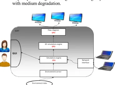
SOFI (“Simulateur Optique pour la Formation d’Image” French acronym for the Image Synthesis Simulator) is an operational underwater exploration mission simulator for submarine vehicles such as AUVs (Autonomous Underwater Vehicles) or ROVs (Remote Operated Vehicles) operating in a realistic three dimensional environment. The challenge is to take into account vehicle’s embedded sensors, light sources, seabed and ocean’s properties to reach a realistic image generation (Fig. 1).
This work has been partially supported by French National Research Agency (ANR) through COSINUS program (project OSIFIOST n° ANR-08- COSI-008), with an additional support through the Pôle Mer PACA.
3
Figure 1. Environment for the synthetic generation of underwater optical images
SOFI aims at enabling users to integrate their own image formation physical models and process them in real time (depending on the model). Real time is a useful feature because the simulator is able to be operated in a complete operational platform c onnected with mission planning software and hardware interfaces like localization and navigation systems.
The complete architecture of the SOFI simulator is represented in Fig. 2. SOFI includes features such as:
• A GUI (Graphical User Interface), • Network capacities,
• An environment server to take into account environment data (maps, …),
• A simulation engine including kinematic and hydro- dynamic vehicle behavior models,
• A 3D rendering engine to get images without any degradation,
• A post-processing flow diagram for image synthesis with medium degradation.
B. Specific features
The main innovative feature developed in the simulator relies on flow diagrams entirely processed and accelerated through graphic hardware for the image and video synthesis. This technique r efers to GPGPU which stands for General- Purpose computing on Graphics Processing U nits [5]. The whole image synthesis rendering pipeline is performed through GPU (Graphic Processing Units) using the DirectX technology (Microsoft Application P rogramming I nterfaces), the HLSL language (High Level Shading Language) a nd the NVIDIA CUDA architecture (Compute Unified Device Architecture) [6]. Manipulation and visualization of the inputs (raw data such as color images without lighting a nd depth map, matrices, vectors and scalars), outputs (synthesized images) and processes (illumination models, convolution, space transforms, …) are described by a set of boxes and links (Fig. 3). Generic boxes and several predefined processes have been implemented using HLSL or CUDA for basic algebra subroutines, the Fast Fourier Transform [7] or the Beer-Lambert illumination model. Then, the GUI allows one to create the flow diagram for image synthesis by combining, ordering and editing any set of algorithms. The integration of new technologies in the simulator associated with the flexibility offered to the user to create its own series of algorithms reveals the huge potential of this simulator. It shows that it can be used to a much larger extent than the field of underwater imagery.
C. Hardware accelerated flow diagram
Three dimensional e nvironment data are rendered using Direct3D pipeline (3D part of Microsoft’s D irectX) which means that all inputs are processed a nd maintained within a GPU device context. The rendering process produces two dimensional r aw images. The idea is to perform the whole image synthesis using 2D post-processes, in order to take benefit from parallel computing, without losing the depth information. Us ing a raw image and a depth map makes possible to perform the 3 dimensional image synthesis like a 2 dimensional image processing which is a highly parallelizable process. The raw data are then processed with algorithms which are coded in HLSL and/or CUDA, using various libraries such as CUFFT (Fast Fourier Transform CUDA library) and CUBLAS (Basic Linear Algebra Subroutines CUDA library). As the main performance obstacle is memory bottleneck [8], which appears when data are transferred
SOFI GUI Flow diagram GPU 3D simulation engine GPU
between CPU and GPU, context Direct3D i nteroperability functions of the CUDA runtime application have been used to keep all data within GPU context.
Raw data Simulation engine
CPU Network
interface Camera Depth
Radiative transfer Image Environment server
Incidence angle Look-Up Tables
Environment data
Figure 2. Architecture of the SOFI simulator
4 D. GPU hardware choice
The simulation tasks have been dispatched between CPU (for sequential base tasks such as vehicle simulation) and GPU (for highly parallelizable tasks such as 3D rendering and image synthesis). The choice of GPU programming for image synthesis tasks was motivated by the gain in performance linked to a high memory bandwidth a nd a large amount of Floating Point Operations per Second (FLOPs) (Tab. I) [9]. In addition, hardware performance evolves faster for GPU than for CPU. Since GPU enables floating point operations on latest hardware, processes such as algebra subroutines a nd Fourier transforms a re possible. O ur first analyses showed that this technology seems appropriate to integrate in the simulator the models used for the generation o f underwater images: the radiative transfer model of propagation of light in the ocean, such as the OSOA model [10], or the global underwater image generation model such as the McGlamery’s model [11].
TABLE I. PERFORMANCE COMPARISON
Type of processor CPU (core i7 980 XE) GPU (Nvidia Tesla C2050) Tera 100 (140000 Intel Xeon 7500)
FLOPs 107.55 GFlops 933 TFlops 1.25 PFlops
Price (€) 950€ 1090€ 50M€
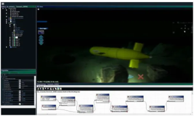
E. RESULT
The architecture of the simulator is now available with the possibility for the user to create his own set of algorithms for image generation, programmed in both languages HLSL and CUDA. The GUI for the simulator is presented in Fig. 4. First tests have been performed and a first flow diagram for image generation has been integrated. It includes a series of processes whose complexity could be comparable to some models of underwater image generation; it consists of:
• rendering raw scene and depth data as textures, • applying the Beer Lambert illumination model using
the previously computed images,
• adding a model for distortion for the lens radial bias, • adding marine snow based on Perlin noise,
• applying a spotlight,
• processing a depth dependent Gaussian blur.
This flow diagram reaches 60 frames per second, thus ensuring real time performance.
Figure 4. GUI of the SOFI simulator
III. IMAGE MODELS
In order to generate synthetic underwater optical images, the simulator requires the integration of realistic image models which rely on the physical phenomena as observed in the ocean. Consequently, the development of the simulator cannot be separated from the study of optical underwater mechanisms which explain light propagation i n the ocean. Underwater images typically suffer from low contrast, limited range, diminished colors with a dominating blue-green hue as well as strong blur. The prominent reasons for these artifacts are the attenuation of light in the water, the directional scattering by particulates, and the strong water absorption in the red spectral range. Thus, the study of the marine visibility within a water body using artificial lighting has been of interest for several decades.
We can distinguish two ways to gain understanding on the processes i nvolved in underwater visibility. One way could consist of using radiative transfer theory based on optical properties of marine particulates to study light propagation in the ocean. Another way is to use image modeling to describe globally how an image is deteriorated under the effects of sea water. Both models, i .e. radiative transfer and global image models, have first been studied and are now under integration in our simulator in order to obtain realistic underwater images.
A. Radiative transfer and the OSOA model 1) The OSOA model
Radiative transfer theory is used to model the propagation of light in the ocean close to the seabed and its interaction with suspended matter [12]. Integrating a radiative transfer model in our simulator is a challenging task because this type of model is quite complex a nd the final product ( simulator SOFI + radiative transfer mode) is very time consuming. So, extensive radiative transfer computations a re first performed using the OSOA radiative transfer model [10]. The OSOA model solves the vector radiative transfer equation for the coupled atmosphere-ocean system using the successive orders of scattering method. Given a set of inherent optical properties (IOPs) in the water column, the OSOA model outputs the angular distribution of the radiance field. The originality of the OSOA model, when comparing to other widely used models such as Hydrolight [13], is to account for the polarization state of light in the water mass. The IOPs required for the computations are the absorption coefficient a, the scattering
5
coefficient b and the phase functions of all compounds in the water. The phase function of the particulates i s of special interest as it describes the angular distribution of the light scattering that results from an incident beam interacting with a volume of water. The bio-optical model of the IOPs close to the seabed considers the pure seawater itself, the suspended particulates, called total suspended matter (TSM), and the yellow substance absorption ( aYS) of dissolved matter. The IOP model includes measurements of the spectral absorption of pure seawater from Smith and Baker [14] and Morel et al. [15], as well as the parameterization of the scattering of the water from Morel [16]. The IOPs of the particulates are modeled using Mie Theory [17]. The absorption of dissolved matter is modeled following Bricaud [18]. Based on these considerations, we focused on 3 types of water for the radiative transfer computations as described in Tab. II. As the IOPs are highly variable with wavelengths, the computations have been performed in the whole spectral range between 400 and 850 nm.
2) OSOA-based look-up tables
The OSOA simulations provide a set of look-up-tables describing the underwater radiance distributions of the light source, the target, and the radiances measured by the camera depending on a defined geometry and on the IOPs. Then, the look-up tables will be used as inputs by the SOFI simulator to compose synthetic optical underwater images.
Further, the generation of look-up tables is also and above all devoted to study the influence of the optical properties of marine particles on the diffusion of the underwater light field.
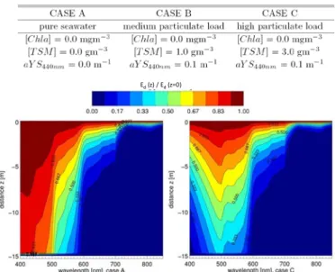
Thus, the simulations performed using the OSOA model confirm some well-known results about the light propagation in the ocean. For example, Fig. 5 represents t he normalized
downwelling irradiance Ed(λ,z) as a function of the wavelength
λ and the distance z. It leads to the conclusion t hat light penetration in clear sea water (case A) is highest for the blue spectral range with a penetration at 15m distance of about 83%. This maximum shifts towards the green spectral range for turbid waters ( case C) and the penetration si gnificantly decreases because the downwelling irradiance drops to only 33% of the initial irradiance at 15m distance. Such a behavior of the irradiance profile was expected but with the extensive simulations, it is now quantified for a quasi-continuous range of wavelengths and distances.
In the same way, Fig. 6 presents the ratio R of upwelling
radiance to downwelling irradiance Ed for case A and case C
relative to distances and wavelengths. I n that case, we can notice that the reflectance ration R rapidly decreases from the blue to the red spectral range in clear waters. On the contrary, in turbid waters, the highest radiance i s located in the green radiations, which is induced by the particulate scattering.
TABLE II. OPTICAL CHARACTERIZATION OF THE DEFINED SIMULATION
CASES A, B, C
Ed (z) / Ed (z=0)
Figure 5. Downwelling radiance ratio Ed(z)/Ed(z=0) for case A and case C
Figure 6. Reflectance ratio R for case A and case C
3) Comparison between OSOA model and Beer-Lambert law
As we said, the aim of these simulations is not only to provide numerical data used as inputs by the SOFI simulator but also to have a detailed insight in the mechanisms of light propagation underwater under artificial illumination. The final goal will be to obtain a simple parametric model which can be used to model the image degradation while taking into account all the optical phenomena encountered in the ocean. The results of the radiative transfer simulations are then compared t o the simplest and widely used description for light propagation along the vertical profile of the ocean which is the Beer- Lambert law. The Beer-Lambert law describes the attenuation of light as an exponential decrease, depending on the attenuation coefficient. It is thus interesting to analyze in which case such a law is a good approximation of the complete radiative transfer.
6
The radiative transfer equation not only accounts for the losses of radiation due to attenuation but also for the gains of radiation due to multiple scattering. Fig. 7 represents the normalized relative difference of the reflectance ratio R derived with the OSOA model and the Beer-Lambert approximation. This figure re veals t hat in clear water (case A), the single scattering scheme is prominent in the blue radiations whereas the multiple scattering process must be considered in the green to red radiations. I n turbid water however, the multiple scattering must absolutely be taken into account as it is the major phenomenon.
B. Global image modeling
Contrary t o the OSOA model which is based on radiative transfer and whose use is quite complex and not immediate to generate images, the global image formation models are now
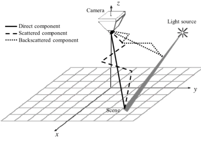
Direct component Scattered component Backscattered component x Camera z Scene Light source y
directly based on the formation of the image on the sensor [11, 19-22] and no more on light propagation. Assuming a “perfect” image which would have been captured on a sensor with no diffusing media, the influence of the diffusing media on the image is then modeled as a degradation of this “perfect” image [11]. This approach has the advantage to operate only few parameters (attenuation coefficient, camera-to-scene distance, …) and allows one to identify the main physical phenomena and the key parameters involved in the degradation of the quality of underwater images [20-22].
Based on the state of the art [11,19,20], the global image formation model that will be implemented in the SOFI simulator assumes that the underwater image is the sum of three components. Two components hold information about the scene: the direct component r epresents t he light which propagates to the camera without being scattered and the scattered component represents the light reflected by the scene and affected by scattering processes. The third component refers to the light which is backscattered to the camera without reaching the scene ( Fig. 8). This model assumes that the degradation due to light propagation in the water (attenuation and scattering) can be described by a convolution on the sensor plane.
ΔR = Rss-Rms/Rms
Figure 7. Relative difference of the reflectance ratio R between model OSOA and Beer-Lambert law for case A and case C
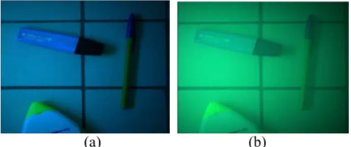
Figure 8. Three components of the global image formation model Using such an approach (see [11,19,20] for details), it is then possible to determine the three components and finally to determine the image observed on the camera. To illustrate the interest of such a global image formation model, we have placed few pens on the floor and captured a 256x256 pixel image with a standard CCD camera (Fig. 9). The whole set-up is in the air (scene and camera). Then, Fig. 10 (a) and Fig. 10 (b) represent the image simulation corresponding to the scene which would have been observed in underwater environment, assuming a 6m scene-camera di stance and assuming that the light source is white and punctual, at a 4m distance on the left from the camera. Fig. 10 (a) corresponds to case A water characteristics, whereas Fig. 10 (b) corresponds to case C water characteristics.
As we said, this image is composed of three additive components, each of them describing a macroscopic physical phenomenon involved in the degradation of the image quality. Thus, the use of a global image formation model allows one to study separately the different sources of degradation on underwater images. One objective of high interest could be to study and predict general tendencies on the degradation of the image quality due to the variations of some image formation parameters (camera-to-scene distance, attenuation coefficient, etc). For example, in Fig. 10 (a), the main source of degradation is due to the absorption of red radiations, whereas in Fig. 10 (b), a veiling light, due to the backscattering phenomenon, is observed over the whole image and degrades the contrast of the objects.
Figure 9. Image (256x256 pixels) acquired with a standard CCD camera into the air.
7
(a) (b)
Figure 10. Example of image synthesis obtained using a global image formation model (a) case A (b) case C
IV. CONCLUSION AND FUTURE WORK
In this paper, we have presented the SOFI simulator which is based on the latest technologies used for computer graphics. Its flexible architecture relies on flow diagrams and allows one to take advantage of the full potential of the technologies to integrate any set of algorithms a s soon as they are highly parallelizable processes. Although the simulator still needs to be validated with models based on optical phenomena encountered underwater, the first results are promising and show t hat it should not be limited to the only field on underwater imagery.
The next step in the simulator development concerns the integration of the two physics-based models which have been described in this paper: the OSOA model via the integration of look-up tables and the global image formation model. While the radiative transfer theory is initially used to study light propagation underwater, i ntegrating the OSOA model to generate images is an innovative a nd interesting way of research as it will allow us to compare complex but accurate models to more simple models such as the McGlamery’s model. A first insight into differences of radiances which could be observed has been shown through the comparison between the OSOA model and the Beer-Lambert law. Furthermore, to complete the validation, the images generated by the simulator should be compared to ground-truth images. But the key issue is not to point up the differences of the models but rather to specify the validity domain of global models. Using simple and global image models has already shown their interest as they can be used to study and develop image algorithms appropriate to the intrinsic nature of the images [23-24]. One point of interest will be to use the global models to design, develop and assess quantitatively image processing algorithms appropriate to underwater images or novel optical instrumentation for underwater vehicles.
REFERENCES
[1] K. Jerosch, M. Schlueter, J.P. Foucher, A.G. Allais, M. Klages, and C. Edy, “Spatial distribution of mud flows, chemoautotrophic communities, and biogeochemical habitats at Hakon Mosby Mud Volcano,” Marine Geology, vol. 243(1-4), pp. 1-17, September 2007.
[2] C. Barufaldi, P. Firoozfam, S. Negahdaripour, “An integrated vision- based positioning s ystem for video stabilization and accurate local navigation and terrain mapping,” MTS/IEEE OCEANS 2003, pp. 2567- 2573, San Diego, September 22-26, 2003.
[3] S.D. Fleischer, S.M. Rock, and R.L. Burton, “Global position determination and vehicle path estimation from a vision sensor for real-
time video mosaicking and navigation,” MTS/IEEE OCEANS 97, Halifax, October 6-9, 1997.
[4] J. Santos-Victor, and N. Gracias, and S. van der Zwaan, “Using vision for underwater robotics: video mosaics and station keeping,” 1st International Workshop on Underwater robotics for Sea Exploitation and Environmental Monitoring, Rio de Janeiro, October 1-3, 2001.
[5] T. Balz, “Real-time sar simulation of complex scenes using programmable graphics processing units,” Symposium on “Remote Sensing: From Pixels to Processes”, Enschede, May 8-11, 2006. [6] M. Garland, S. Le Grand, J. Nickolls, et al., “Parallel computing
experiences with CUDA,” IEEE MICRO, vol. 28(4), pp. 13-27, 2008. [7] O. Fialka, and M. Cadik, “FFT and convolution performance in image
filtering on GPU,” 10th International Conference on Information Visualization, pp. 609-614, London, July 05-07, 2006.
[8] S. Ryoo, C.I. Rodrigues, S.S. Baghsorkhi, et al., “Optimization principles and application performance evaluation of a multithreaded GPU using CUDA,” ACM SIGPLAN Symposium on Principles and Practice of Parallel Programming , pp. 73-82, Salt Lake City, February 20-23, 2008.
[9] S. Che, M. Boyer, J.Y. Meng, D. Tarjan, J.W. Sheaffer, and K. Skadron, “A performance study of general-purpose applications on graphics processors using CUDA,” Journal of parallel and distributed computing, vol. 68(10), pp. 1370-1380, 2008.
[10] M. Chami, R. Santer, and E. Dilligeard, “Radiative transfer model for the computation of radiance and polarization in an ocean-atmosphere system: polarization properties of suspended matter for remote s ensing,” Applied Optics, vol. 40(15), pp. 2398-2416, 2001.
[11] B.L. McGlamery, “A computer model for underwater camera systems,” Ocean Optics VI, vol.208, pp. 221-231, 1979.
[12] C.D. Mobley, “Light and water: radiative transfer in natural waters,” Academic Press, New York, 1994.
[13] C.D. Mobley, “A numerical model for the computation of radiance distributions in natural waters with wind-roughened surfaces,” Limnol. Oceanogr., vol. 34, pp. 1473-1483, 1989.
[14] R.C. Smith, and K.S. Baker, “Optical properties of the clearest natural waters (200–800 nm),” Applied Optics, vol. 20, pp. 177-184, 1981. [15] A. Morel, B. Gentili, H. Claustre, M. Babin, A. Bricaud, J. Ras, and F.
Tièche, “Optical properties of the “clearest” natural waters,”. Limnol. Oceanogr., vol. 52, pp. 217-229, 2007.
[16] A. Morel, “Optical properties of pure water and pure sea water,”. In Optical aspects of oceanography. Jerlov N. G., Steeman-Nielsen E. (eds.). Academic Press, London, pp. 1-24, 1974.
[17] C.F. Bohren, and D. Huffman, “Absorption and scattering of light by small particles” Wiley, New York, 1983.
[18] A. Bricaud, A. Morel, and L. Prieur, “Absorption by dissolved organic matter of the sea (yellow substance) in the UV and visible domains,” Limnology and Oceanography, vol. 26, pp. 43-53, 1981.
[19] J.S. Jaffe, “Monte-Carlo m odeling of underwater image formation - validity of the linear and small-angle approximations,” Applied Optics, vol. 34(24), pp. 5413-5421, August 1995.
[20] S. Negahdaripour, H. Zhang, and X. Han. “Investigation of photometric stereo method for 3-d shape recovery from underwater imagery”, MTS/IEEE Oceans 2002, pp. 1010 - 1017, Biloxi, 2002.
[21] E. Trucco, and A.T. Olmos-Antillon, “Self-tuning underwater image restoration,” IEEE Journal of Oceanic Engineering, vol. 31(2), pp.511- 519, April 2006.
[22] R. Schettini and S. Corchs, “Underwater image processing: state of the art of restoration and image enhancement methods,” EURASIP Journal on Advances in Signal Processing, 2010.
[23] Z.S. Liu, Y.F. Yu, K.L. Zhang, and H.L. Huang,”Underwater image transmission and blurred image restoration,” Optical Engineering, vol. 40(6), pp. 1125-1131, June 2001.
[24] Y.Y. Schechner, and N. Karpel, “Clear underwater vision,” IEEE Computer Vision and Pattern Recognition, vol. 1, pp. 536-543, 2004.