3D-printing Form and Function
by
Subramanian Sundaram
B.E. Electrical & Electronics Engineering,B.E. Mechanical Engineering.
Birla Institute of Technology and Science, Pilani, India (2011) S.M.. Massachusetts Institute of Technology (2014)
Submitted to the Department of Electrical Engineering and Computer
Science
in partial fulfillment of the requirements for the degree of
Doctor of Philosophy in Electrical Engineering and Computer Science
at the
MASSACHUSETTS INSTITUTE OF TECHNOLOGY
September 2018
@
Massachusetts Institute of Technology 2018. All rights reserved.
Signature redacted
A uthor ...
Department of Electrical Engineeri g and Computer Science
June 8, 2018
C ertified by ...
Signature redacted
KWojciech Matusik
Associate Professor of Electrical Engineering and Computer Science
Thesis Supervisor
Signature redacted
A ccepted by
...Lesli'AJ Kolodziejski
Professor of Electrical Engineering and Computer Science
MASSA INSTITUTE
LRECHOLOG
UCi'1' 10 2018
Chair, Department Committee on Graduate Students
C03D-printing Form and Function
by
Subramanian Sundaram
Submitted to the Department of Electrical Engineering and Computer Science on June 8, 2018, in partial fulfillment of the
requirements for the degree of
Doctor of Philosophy in Electrical Engineering and Computer Science
Abstract
Integrating diverse functions inside man-made parts with specific shapes, in a highly scalable manner, is the central challenge in manufacturing. Functional integration is typically achieved by assembling specialized parts, each independently made using carefully designed production techniques - for example, in assembly lines in the auto-motive industry. Externally assembling specialized parts is tedious at certain length scales (e.g. mesoscale manufacturing), imposes restrictions on achievable geometries, and limits functional integration.
In contrast, nature excels at packing disparate materials and functions into uncon-strained geometries across different length scales (e.g. distributed sensors in cuttlefish, or sensorimotor pathways and resonant muscles in insects). These far exceed our cur-rent fabrication capabilities, and replicating all the functions of natural systems has remained a distant dream. 3D-printing has resolved many challenges in fabricating complex geometries, but despite its promise, assembling diverse materials (including solids, liquids and thin-films) and functions inside a single, printed composite is a current challenge.
This thesis presents a set of materials, processes and design strategies - a full ex-perimental toolkit - to address the question: how can we distribute diverse materials
and functions in free-form geometries? First, a fully-3D-printed autonomous
com-posite that can sense an external stimulus, process it, and respond by varying its opti-cal transparency is described. The composite consists of seamlessly integrated solids (UV-cured polymers), thin-films (conducting and semiconducting, solvent-evaporated films), and encapsulated liquids. Techniques to engineer material interfaces are also presented in this section.
A stimulus-free strategy to 3D-print self-folding composites at room temperature
is presented in the second part of this thesis. Specifically, the focus is on printing flat electrical composites that fold into pre-programmed shapes after printing using residual stress defined in specific regions. This provides advantages in the fabrication speed, and also expands the range of achievable geometries when using solvent-based inks. The third portion of this thesis focuses on 3D-printing soft actuators. After highlighting a few example applications of printed actuator arrays, this is used as a
case study for topology optimization based design strategies. It is shown that the inclusion of a topology optimizer in the 3D-printing pipeline enables the automated design and fabrication of high-dimensional designs. The final section of this work focuses on creating tactile sensor arrays, with an emphasis on the acquisition of tactile datasets that can be used to understand the human grasp. The concluding section summarizes the role of the fabrication strategies presented here in creating composites of increasing levels of autonomy and self-sufficiency.
Thesis Supervisor: Wojciech Matusik
Acknowledgments
Very little of my graduate school experience was predictable. My time at MIT was full of surprises and challenges, and more importantly, filled with enjoyable learning experiences. I am thankful to all the fantastic people I crossed paths with, over the past nearly seven years.
Through all these years, Professor Marc Baldo's guidance was one of the few constants. I met him during my first days at MIT, and I am lucky to have had the chance to interact with him all along. Even when we weren't directly collaborating, Marc was an amazing role model who inspired me with his focus on the scientific process. Marc's impact on this thesis and my career are significant, and I'm incredibly fortunate for this. I am thankful to my advisor, Professor Wojciech Matusik for his support through the last four years. He gave me the resources and the freedom to work on projects of my choice with no restrictions. He also encouraged me to develop my own ideas, take them to completion, and become independent. I find his persistence and passionate pursuit of his own projects quite inspiring. I thank him for his enthusiasm in supporting my career pursuits. I am deeply thankful to Professor Vladimir Bulovid for being part of my thesis committee and for offering his perspective on my projects. His comments on both the low-level details and the big picture guided my presentation of ideas in this thesis.
I am extremely thankful to Professor Ryan Hayward at the University of
Mas-sachusetts, Amherst - he was such a pleasant collaborator. He helped me understand many ideas in polymer science, and I specifically thank him for his help in the "self-folding composites" project. He kindly hosted me at his lab, and was generous with sharing his ideas on many topics.
My interest in tactile sensors and the human grasp grew out of early discussions
with Professor Antonio Torralba, Professor Russ Tedrake and Professor Ted Adelson.
I am thankful to them for their wisdom and for our regular meetings which were
thoroughly enjoyable. It was also a constant reminder of how amazing CSAIL is. Thanks to Professor Dina Katabi for collaborating with us on printed antennas and
also for many pleasant conversations. Professor Ron Weiss taught some of my favorite courses on synthetic biology and was an excellent teacher.
I am fortunate to have worked with Professor Herbert Shea at the Ecole
Polytech-nique F6ddrale de Lausanne as an undergraduate - I continue to rely on his advice
and friendship. Thanks to Professor Klaus Kern at the Max Planck Institute for Solid State Research and Professor Kannan Balasubramanian (now at Humboldt Univer-sity, Berlin) for helping me get an early start on research at a rigorous environment.
My interest in research originated in the offices of Professor N. N. Sharma and the
late Professor R. Mehrotra at BITS, Pilani. My undergraduate mentors played an importantly role in my decision to join a graduate program - it was in these labs where I first experienced the joys of research.
I am thankful to David Kim, Louise van den Heuvel and Melina Skouras for being
excellent collaborators and contributing ideas to the magnetic actuators project. The work on automated design and fabrication used many of Melina's simulation and optimization tools. Omid Abari and I had great fun working on printed antennas. Ziwen Jiang and Julia Rubin were ideal UROPs - it was exciting to mentor them and be around their boundless enthusiasm. I would like to thank Pitchaya Sittthi-amorn (Yam) who taught me much about our 3D-printer during my first days in the lab. Thanks to all my labmates at the Computational Fabrication Group for their friendship and being great colleagues. In particular, I want to thank James Minor for proofreading parts of this thesis.
I also want to thank Professor Jeff Lang and Professor Tomas Palacios for helpful discussions during the course of my projects. Daniel Piedra was generous enough to let me use his measurement setup to characterize my printed transistors, sometimes even during the weekends. My experiments and characterization measurements also benefited from the advice of countless research staff at MIT. I want to thank Geetha Berera, David Bono and Timothy McClure in particular for their help with material characterization. Thanks to Paul Tierney, Dennis Ward, Donal Jamieson, and the MTL staff for their help with my fabrication processes during my first 3 years at MIT, a large part of which I spent at the MTL cleanroom.
I am extremely grateful to my dear friends for supporting me and inspiring me throughout this journey. Finally, this thesis would not have been possible without the support and encouragement of my mother and my grandmother. They enabled much of what I have today through their continuous sacrifice, foresight and resilience. I am forever thankful to them.
Contents
1 Introduction
1.1 Autonomous Composites . . . . 1.2 3D-printing and additive manufacturing . . . . 1.3 T hesis overview . . . .
I
3D-Printed Multimaterial Composites
2 Drop-on-demand 3D-printing
2.1 Inkjet-based 3D-printing . . . . 2.2 Ink requirements and processing . . . .
2.3 Material interface engineering . . . . 2.3.1 Effect of surface energy . . . .
2.3.2 V oxel filling . . . .
2.3.3 Surface texture . . . . 2.3.4 Geometric control of interfaces . . . .
3 Autonomous sensory composites
3.1 Fabrication of sensory composites . . . .
3.2 Printed strain sensor . . . .
3.3 Organic electrochemical transistors (OECTs) and amplifiers 3.4 Electrochromic pixel . . . .
3.5 Integrating the parts . . . .
3.6 Experimental methods . . . . 21 23 25 27
29
31 32 33 37 37 39 40 42 43 . . . . . 43 . . . . . 45 . . . . . 51 . . . . . 54 . . . . . 55 . . . . . 57II Generating Shape by Programmed Self-Folding
60
4 Polymer swelling induced residual stress 61
4.1 Printing materials with residual stress . . . . 62
4.2 Role of crosslink density . . . . 64
5 Self-folding electronic composites 71 5.1 Shape transformation in electronics . . . . 71
5.2 4D -printing . . . . 72
5.3 Self-folding bilayer . . . . 74
5.4 Modeling the self-folding system . . . . 77
5.5 Self-folding composites . . . . 85
5.6 Experimental methods . . . . 91
III 3D-Printed Actuators
-
a case for automated design 93
6 Multimaterial magnetic actuators 95 6.1 3D-printed mesoscale magnetic actuators . . . . 956.2 Magnetic actuator characteristics . . . . 102
6.3 Experimental methods . . . . 107
7 Topology-optimization for automated design and fabrication of ac-tuators 113 7.1 Multi-objective topology optimization . . . . 115
7.2 Printed topology-optimized actuators . . . . 120
7.3 Experimental methods . . . . 123
IV
Tactile Skins for Understanding Human Grasp
126
8 Tactile sensor arrays & gloves 127 8.1 Fabrication of a regular array . . . .1288.3 Sensor array and readout circuit . . . . 132
8.4 Extensions to the sensor array . . . . 135
8.5 Towards tactile gloves . . . . 138
8.6 Future work . . . . 140
9 Conclusions 143 9.1 Future w ork . . . . 144
List of Figures
1-1 Autonomous Composites . . . . 24
2-1 Schematic of functional parts of our printer . . . . 33
2-2 Resolution and droplet size . . . . 34
2-3 Three ways to convert ink to final use materials . . . . 36
2-4 Surface energy measurements from droplet shapes . . . . 38
2-5 Voxel filling strategies . . . . 41
2-6 Surface texture of the electrical contacts . . . . 42
3-1 Golden Tortoise Beetle (Charidotella sexpunctata) . . . . 44
3-2 Schematic of the autonomous sensory composite . . . . 46
3-3 Stress-strain measurements of the UV curable materials - RIG and ELA 47 3-4 Strain sensor design and performance . . . . 48
3-5 Strain sensor performance under high strain . . . . 49
3-6 Strain sensor performance under repeated cycling . . . . 50
3-7 Printed organic electrochemical transistor (OECT) - design and per-form ance . . . . 52
3-8 Transistor performance characteristics - transfer, I-V curves . . . . . 53
3-9 Single-stage common source amplifier properties . . . . 54
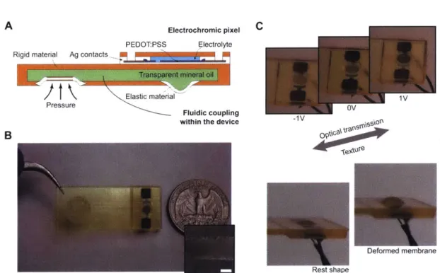
3-10 Electrochromic pixel design and performance . . . . 55
3-11 Device with fluidic coupling enables controlling transparency and shape 56 3-12 Integrated autonomous sensory composite tests . . . . 58
4-2 FTIR spectra of STR samples with varying levels of crosslinks . . . . 65
4-3 Double bond conversion and cure depth of STR samples . . . . 66
4-4 Linear strain due to swelling and mechanical properties (STR) . . . . 67
4-5 Mechanical strain tests of printed STR slabs . . . . 68
4-6 Differential scanning calorimetry (DSC) and dynamic mechanical anal-ysis (DMA) data - RIG and STR . . . . 69
5-1 Overview of self-folding composites . . . . 75
5-2 Characteristics of the bilayer system used for creating folds. . . . . . 76
5-3 Bilayer characteristics at elevated temperatures and design guidelines 78 5-4 Modeling the folding in the bilayer geometry - extracting prescribed strain . . . . 82
5-5 Folding angle measurements and comparison with simulation . . . . . 83
5-6 Effect of heating and high UV dose on the folding process . . . . 84
5-7 Electronic self-folding composite design . . . . 86
5-8 Self-folding electronic composites . . . . 88
5-9 Measured folding angle with mechanical stops . . . .. 89
5-10 Unfolding forces . . . . 90
6-1 Magnetic actuators - material property library . . . . 97
6-2 Magnetic actuators - supplementary material characteristics . . . . . 97
6-3 Actuator general design . . . . 98
6-4 Printed actuator arrays . . . . 99
6-5 Magnetically actuated displays . . . . 100
6-6 Magnetic actuation at fluid interfaces . . . . 101
6-7 Experimental verification of tilting angles . . . . 104
6-8 Modeling of the external magnetic field . . . 105
6-9 Force generated by our actuators ... . . . .. . . . . .. 105
6-10 Switching transients and bandwidth measurements - small amplitude regim e . . . . 106
6-12 Long term cycling test of the small actuator . . . .1
7-1 Topology optimization for function driven actuator fabrication . . . . 115
7-2 Panel appearance computation . . . . 117
7-3 Dot gain im ages . . . . 118
7-4 Panel optimization for both optical and mechanical properties . . . . 121
7-5 Force and deflection measurements of the topology optimized actuator 122 7-6 Long term cycling test of lp = 19 mm actuators . . . . 123
7-7 Topology optimized actuator array - grass and stones . . . . 124
8-1 Schematic of the tactile sensor array . . . . 129
8-2 Strain sensor characteristics and long term cycling . . . . 131
8-3 Sensor characteristics of 3 devices . . . . 132
8-4 Readout scheme for the tactile sensor array . . . . 133
8-5 Fabricated 32 x 32 sensor arrays . . . . 134
8-6 Captured 10 object dataset of visual and tactile images . . . . 136
8-7 Auxetic patterns for sensor arrays . . . . 137
8-8 Thermal characteristics of the pressure sensitive film . . . . 138
8-9 Tactile glove . . . . 139
8-10 Future work . . . . 141
List of Tables
2.1 Surface tension of probe liquids . . . . 39
2.2 Contact angles of probe fluids on RIG and ELA . . . . 39
2.3 Surface energy of cured RIG and ELA . . . . 39
A.1 Ink formulations for devices in Part I . . . . 149
A.2 Ink formulations for devices in Part II . . . . 150
Chapter 1
Introduction
Modern day manufacturing relies on the use of specialized manufacturing methods to produce parts ranging from automobiles and airplanes to robots and medical implants. These end products vary significantly in size, material composition and complexity, but importantly, also have great variance in the number and kind of custom-made machines and tooling required to produce them. Manufacturing industries are op-timized to produce identical parts in large quantities using processes that are fast and efficient in their use of raw materials. Manufacturing of these modular parts has been a tremendous success story and is one of the foundations of industrialized economies. At the same time, this has also furthered an assembly-centric approach to manufacturing. Specifically, when multiple functional parts are required to build a larger system, they are typically produced individually and then assembled in a traditional assembly line.
It is possible to imagine new paradigms in manufacturing that can overturn this model, which is of extreme interest as any improvements in this broad framework would have large impacts on economically vital industries. Several broad alternatives and ideas are being explored today. Some important questions that are being asked are:
1. We can produce identical parts in a high-throughput manner. Can we produce
2. Manufacturing equipment is often prohibitively expensive. Will home users be able to produce small quantities of parts using low cost machines?
3. Can we manufacture parts with complex shapes?
4. Can one low-cost machine produce more than one type of part?
5. How can a non-expert user design these parts quickly?
6. If these simpler hobbyist machines become pervasive, will we rely less on
ship-ping and more on digital transfer of design files?
Three-dimensional printing (3D-printing, sometimes more broadly referred to as ad-ditive manufacturing [AM]), is emerging as a promising approach to explore these fabrication challenges. As these questions are being answered, the face of manufac-turing is itself evolving. At a fundamental level modern products are increasingly optimized, and pack functions more densely together. These functions span multiple domains - electrical, mechanical, optical and so forth. The bigger challenge comes from our current reliance on modular parts as we enter the era of mass customiza-tion. When customizing small objects like hearing aids, the amount of "real estate" is small and we can no longer use modular parts - modularity costs space. Products of the future will be designed and fabricated in a completely integrated way resembling natural organisms.
This thesis is aimed towards the broad challenge of achieving the levels of func-tional integration seen in nature. Consider the sensorimotor pathways seen in natural organisms. These pathways are made up of individual elements that have a multitude of functions, and are arranged in close proximity in three dimensions. These func-tions are further defined at multiple length scales and hierarchies, and are created by assembling materials from a diverse palette. This density of functional and material integration enables much of the autonomy, efficiency and reliability of natural sys-tems. Replicating this level of functional integration has been extremely challenging, even using additive manufacturing techniques. We largely rely on external assembly
for functional integration, and can't densely pack diverse materials in freeform geome-tries. Simply put, our fabrication capabilities are limited compared to strategies used
by nature. The ability to replicate even a part of natural integration strategies would
be useful for applications in fields like robotics. This thesis addresses the question:
"How can we integrate diverse
functions
in parts with unconstrained geometries?"More specifically, the focus here is on functional elements that contribute to autonomy, such as sensors, processors and actuators. This is in part motivated by their pervasive presence in intelligent machines and robots. It is desirable to integrate these elements into seamless parts with complex 3D-geometries to form autonomous composites. Fabricating these composites requires the fundamental ability to arrange disparate materials - solids, liquids and thin films -freely in three dimensions and engineer their interfaces. More generally, fabricating form and function without external assembly demands precise control of material integration. This thesis describes in detail the materials, design approaches, device designs, fabrication processes and experimental methods to produce minimal versions of these autonomous composites.
1.1
Autonomous Composites
Mixing multiple materials to build composites with improved performance is an old, time tested strategy. For instance, wattle-and-daub is a composite structural material has been used for several millennia to make walls1. The idea that the right materials can be brought together to create arbitrary functions inside smart composites2 is
widely accepted today. These composites can be considered primitive man-made analogues of biological systems. When a wide range of functions are simultaneously integrated in a composite, the boundary between materials and machines is blurred3.
Specifically, we can envision such a composite where many sensors that sense external or internal stimuli are distributed freely in the structure. The received stimuli are processed using distributed signal processors and an appropriate collective response is effected by actuators. These composites would be able to communicate among
A Communicate B Actuators O Sensors Energy Source Structural Processors parts
Figure 1-1: Autonomous composites. A. Autonomous composites integrate ele-ments that enable basic autonomy into a single composite that is structurally stable and self-sufficient. Additionally, they allow individual composites to communicate with each other to perform coordinated tasks. B. One can abstractly segment these functions (and materials) into discrete compartments within a seamless composite.
themselves and with the outside world over extended periods of time with access to an energy source. When all these individual functions are brought together to enable autonomy, we define these composites as Autonomous composites, as shown in Fig.
1-1. Amorphous computing4 and robotic materials5
are analogous ideas that exist in robotics.
Aggregations of diverse functions that exist is nature have often served as inspi-ration in robotics and other related fields. (i) Cuttlefish are able to quickly sense the surrounding scene and camouflage themselves rapidly and effectively. This is possible due to their ability to locally sense light and respond by controlling the chromatophores on their skin6
. (ii) The human tactile system has equally intrigued robotics - we cannot yet match the number or density of mechanoreceptors in the
human palm7 in contemporary robots. This has limited our ability to both under-stand the primate grasp as well as use a similar system in robots. (iii) Insect flight is enabled by a sophisticated control system that consists of sensors and efficient reso-nant actuators. For example, the fruit fly uses inputs from both vision and antennae mechanoreceptors to stabilize itself in flight'. These examples highlight the long-standing roadblocks that exist in building hardware for robotics, and it is easy to see the role that artificial autonomous composites have in addressing this. Biomimetic and bio-hybrid functions feature prominently in the grand challenges of robotics9.
The recent surge in interest in biomimetic functions has happened in parallel with rapid improvements in fabrication technology in diverse fields - this has enabled fascinating new directions of inquiry. There have been many advances in using self-assembly techniques across vastly differing length scales10 and advances in MEMS and semiconductor fabrication technologies have led to proposals such as the smart dust project11. Emerging advances in genetic engineering and synthetic biology have
enabled the paradigm of biological fabrication". In addition, over the past three decades, 3D-printing techniques have come into the picture and have grown rapidly. This is the fabrication method explored here due to its advantages in creating free-form geometry and its ability to handle a diverse materials palette.
1.2
3D-printing and additive manufacturing
In 1981, Hideo Kodama described a way to fabricate 3D models using a photo poly-mer 1 3. This, along with Chuck Hull's first patent'4, is considered to be the beginning
of 3D-printing as we know it today. It has since become a term for a collection of different techniques that enable the creation of parts made of diverse materials us-ing additive processes. In general, most 3D-printers enable fabrication of complex structures by assembling powders, inks or filaments using a motion controlled stage (or gantry). The printhead is the active material deposition system which can be an inkjet printhead, a filament extruder, or even a controlled light source that dictates curing. A detailed description of all the different 3D-printing methods is beyond the scope of this work, but a short description of a few popular techniques is given below:
1. Stereolithography (SLA): In SLA techniques, a liquid resin is contained in a bath
and can be selectively photo cured one volume element (voxel) at a time or one layer at a time. Subsequently, the stage on which the layer is polymerized is advanced to create the next layer on top. SLA is considered the first 3D-printing process.
nozzle which is mounted on a gantry. Typically, the extruder (or printhead) is mounted on a 2-axis gantry and the printer platform provides the 3rd axis of
control. FDM is the most widely used consumer 3D-printing process.
3. Powder-based 3D-printing: In powder based additive manufacturing, powdered
plastic or metal is bound together by using a binder (which is inkjet on top) or sintered using a laser source. In this process the resultant part is often
green (i.e., requires further processing) and the material properties are typically enhanced by post-processing methods. Powder based 3D-printing techniques occupy a large part of the industrial 3D-printing space.
4. Drop-on-demand 3D-printing: This is an extension of the more common 2D inkjet printing process used in desktop inkjet printers. Drop-on-demand 3D-printing involves the use of UV-curable inks that can be deposited using a heated printhead that can be subsequently cured after deposition. These techniques have significant advantages in their multimaterial manufacturing capabilities.
5. Direct ink write (DIW): In a typical DIW process, material is extruded through
a nozzle by using a high pressure air inlet. The printer setup is analogous to the FDM process and the printing process is controlled using a vector motion controller. This process is widely used in academic research today due to its simplicity and freedom in material compatibility.
3D-printing rivals traditional processing in its ability to work with complex mate-rials, and exciting examples of 3D-printed devices demonstrating novel functional ca-pabilities have recently begun to emerge. These developments are often accompanied
by variations and improvements in the printing process itself. Recent demonstrations
have produced a wide range of materials: polymer-derived ceramics15, a bone replace-ment 1 6, transparent fused silica glass 17, and stainless steels with high strength
18, to
name just a few. With the ability to achieve superior material properties, atten-tion is now shifting to the funcatten-tions that can be created using 3D-printing. So far a range of functional devices such as micro-batteries 19, quantum dot light emitting
diodes (LEDs)20, strain sensors21, satellite propulsion systems22, hydraulically-driven
robots,2 3 and dielectric elastomer actuators2' have been 3D-printed. These few ex-amples highlight the breadth of devices that can be printed. However, the typical challenge is in fully printing all parts of these devices completely (i.e. not relying on any external processing) and integrating diverse components inside the same part using the same printing process.
1.3
Thesis overview
The objective of this thesis is to enable the integration of diverse functions inside objects of complex shapes - this is in part inspired by the limitless freedom in the integration of functions seen in natural organisms, as mentioned earlier. The main hypothesis here is that this is only possible if we are able to integrate diverse materials in free-form geometries. Furthermore, the ability to control the placement of these materials and engineer their interfaces is an essential requirement. With this in mind, we develop fundamental ideas for integrating solids, liquids, and thin-films together. Material interfaces can be controlled by designing the materials themselves or by controlling physical properties such as surface texture and geometry. Part I explores material interfaces in detail in the context of autonomous sensory composites - an integration of sensing, processing, and output devices. This is the first demonstration of fully 3D-printed transistors that are integrated together to form amplifiers inside a matrix that consists of rigid and elastic materials. The next part of the thesis, part II, presents a new folding technique based on programmed residual stress. This allows programmed spontaneous folding in a printed object once it is removed from the printer platform, i.e. without any controlled stimulus. In part III, we devise a strategy to design and fabricate magnetically-actuated panel arrays. Notably, the focus is on an automated design and fabrication scheme that utilizes a fabrication-aware optimization process. The first three parts of the thesis are based on a voxel-based 3D-printing approach. The subject of part IV is the fabrication of tactile arrays and gloves. The main goal of this part of the thesis is to demonstrate a rapid and
scalable scheme for obtaining tactile data when humans grasp objects. Finally, the last chapter of the thesis summarizes the results and presents potential directions to build upon this thesis.
The main thesis of this dissertation can be summarized as follows:
Achieving seamless functional integration in free-form geometries is built on the ability to arrange a disparate set of materials (solids, liquids, and thin-films). Further-more, controlling the arrangement of these materials and engineering their interfaces is important. Combining these capabilities with computational design synthesis tech-niques enables the automated fabrication of parts with dense functional integration.
Specifically, the main contributions of this thesis are listed below:
" We present the first integration of 3D-printed transistors with sensors and
ac-tuators to form autonomous composites within a single printing process.
" We outline techniques to control interfaces between solids, liquids, and
thin-films in a 3D-printing process.
" We demonstrate a new process to control shrinkage/expansion in 3D-printing.
Using this capability, we present a new self-folding process that requires no controlled external stimulus.
* By combining a design generation technique with 3D-printing, we demonstrate the automated design and fabrication of multimaterial actuators in a
high-dimensional design space (> 106 design variables).
" We present a scalable technique to fabricate dense tactile sensor arrays and
Part I
3D-Printed Multimaterial
Composites
Chapter 2
Drop-on-demand 3D-printing
Inkjet printing, despite its conception over a century ago, reached wide adoption in the second half of the 2 0th century. It was during this time when
microelectromechan-ical systems (MEMS)-based printhead technologies (piezoelectric or thermal droplet generation systems) were developed, and came into broad use. In traditional inkjet printing, droplets are generated (typically ~ 50 pm) and can each be independently controlled and positioned on a substrate. These droplets are then dried by evapo-rating the solvent, absorbing them onto a substrate, or solidified25. These droplets
can be triggered at a frequency up to 1 - 20 kHz per nozzle, and typically each print-head contains up to 100s of nozzles. While it is still widely used in graphics output and marking on paper, it has emerged as a promising manufacturing technology in
different fields26 ranging from printed electronics27-29, nucleic acid synthesis30, and
biological cell printing313 2. The most compelling case for the use of inkjet printing,
as far as this thesis is concerned, comes from its multimaterial capability and ability to actuate a large number of nozzles that can be independently triggered at any given time. We now describe our custom built drop-on-demand 3D-printer that contains multiple piezoelectric printheads, and can support multiple diverse materials.
Contents of this chapter are adapted with permission from -S. Sundaram, Z. Jiang, P. Sitthi-Amorn, D. S. Kim, M. A. Baldo, W. Matusik, "3D-printed autonomous sensory composites", Adv.
Mater. Technol., 2, 1600257 (2017). https: //doi. org/10.1002/admt.201600257 [Copyright John
2.1
Inkjet-based 3D-printing
Drop-on-demand inkjet 3D-printing is an extension to the traditional 2D inkjet print-ing process. The transition to fabrication in three dimensions requires new hardware, design strategies and inks - all of which will be addressed in this thesis. The hard-ware consists of a 3D gantry - where the printhead is mounted on a carriage that can typically move in 2 axes and a printer platform which moves in the third dimension, often the z-axis. Our 3D-printer consists of two commercial printheads (from the Ep-son Workforce 30 printer), and can print up to a maximum of 10 different materials simultaneously33. Each printhead has 540 individual nozzles. The inks to be printed are connected to the printhead and maintained at an optimized pressure using an air-input pressure control system. The pressure (positive or negative) is optimized based on the fluidic resistance of the path from the connector to the printhead nozzle. Each of the printheads can be connected to 5 unique inks. In our case, one print is heated to a temperature of 70 'C. So all the inks connected to this printhead have to be stable at this temperature, and also lie in the printable viscosity and surface tension range. The ink requirements are described in more detail later. The heated printed is typically used with UV curable inks in our printer. This is generally be-cause most UV curable inks and resins tend to be higher in viscosity (~120 cP) than what the printhead is designed for (2 - 15 cP). Here temperature is used to reduce
the ink viscosity to the printable range. The second printhead is maintained at room temperature and is used with all other inks. Apart from the two printheads, the carriage also contains energy sources - a heater and a UV LED array. The typical use of these energy sources is described in the next section.
The 3D-printing process begins with the voxelization of the 3D design to be printed. The voxel dimensions are chosen based on the typical droplet size. Our
printheads are optimized for producing droplets that are - 30 Jim in size. The
typi-cal voxel dimensions we use are 35 pm x 35 pm x 17 11m. A typitypi-cal droplet imaged midair is shown in Fig. 2-2A, and printed lines that are single voxel wide show the
Pressure control' Main ControllerI system
Ceramic heater Air input Inks Pressure
with copper block UV LED sensors
Yara Heater + UVL
LED controller Printhead
1z
Heated Non-heated
printhead Printhead
Figure 2-1: Schematic showing the functional parts of our printer. The printer consists of a carriage that moves in-plane (x and y-axis) and a platform that moves vertically (z-axis). The carriage consists of two printheads, one heated and one maintained at room temperature. Inks fed to the printhead are deposited on the printer platform. Subsequently, they are either UV-cured using the UV LED array, or heated using a ceramic heater, or left as ink inside a printed well to be encapsulated later. The process parameters and gantry are controlled by a central processor.
3D structure into individual voxels arranged in a lattice. Each voxel can then be
assigned a material number that corresponds to a specific material. The end result is the deconstruction of the 3D design file in a stack of bitmaps where each pixel corresponds to the material assignments to corresponding voxel in the slice. Once this voxelized input file is generated, the motion control system and the printhead driver can be used to trigger droplets from individual nozzles at the right positions.
2.2
Ink requirements and processing
Drop-on-demand inkjet printheads impose strict restrictions on the ink rheology. At a basic level the ink cannot contain any particulate matter that can clog the nozzles. In practice, the particulate content has to be less than one-tenth the size of the nozzle to prevent clogging. There are several ink rheology conditions to be met for it to be printable. The Z-number has to lie in the range 1 < Z < 10; Z is a non-dimensional
parameter defined as the inverse of the Ohnesorge number (Oh)2 2. The Ohnesorge
number relates the viscous forces to the inertial forces and surface tension of the ink
B
Figure 2-2: Droplets and resolution A. Images shows droplets after ejection from
4 adjacent nozzles. The droplets are ~ 30 pm in size and the nozzle spacing is ~ 140
pm. B. Lines printed from adjacent nozzles show the lateral resolution of the printing process.
as follows
Oh = (2.1)
,pya
where p, v, -' are the density, dynamic viscosity and surface tension respectively,
and a is the nozzle size. In short, at low Z, the dynamic viscosity dominates the picture, and ink ejection is prevented. Where as at high Z, the inertial forces are too large and this results in many satellite droplets and unwanted spraying. The ideal condition for droplet ejection is the generation of one droplet per actuation cycle with clear separation of the droplet tail. In order to enforce this, we use a droplet-in-flight analysis system with stroboscopic illumination (jetXpert) to observe the droplets as they leave the nozzle (Fig. 2-2A). The droplet ejection force can be controlled by changing the actuation pulse and the waveform that is used to drive the piezoelectric stack corresponding to each nozzle. The actuation waveform contains 1-3 pulses to eject a single droplet, and is optimized manually for each ink. The number of pulses, their amplitude, and duration of these pulses control the droplet volume, ejection velocity and the shape of the droplet. The optimized droplet waveform for each ink is used as an input in the printing process. Prior to optimizing the droplet waveform, the ink viscosity and surface tension are tuned to printable range for our printhead (viscosity typically in the range 2 - 12 cP, and surface tension 40 - 50 mN/m). Ink
rheology optimization and waveform optimization are performed outside the printing
platform. Once the inks are optimized they are loaded in the printer for printing as described earlier.
The inks described in this thesis are typically processed in one of three ways as highlighted in Fig. 2-3. One category of inks, i.e. UV curable inks, contain acry-late based monomers, oligomers, UV photoinitiators and crosslink inhibitors. The monomer and oligomers of the mixture can be varied to create final polymers with varying properties including a wide range of mechanical properties. The photoini-tiator generates free radical when exposed to 365 nm UV light and the monomers and oligomers form chemical crosslinks as a result. The degree of crosslinks is also dependent on the concentration of the photoinitiators. The crosslink inhibitors are used to prolong the pot life of the ink by preventing the formation of crosslinks under low intensity exposure. In this thesis several variants of the acrylic ink are used in subsequent chapters: a rigid formulation (RIG), elastic formulation (ELA), a material with inbuilt residual stress (STR), and magnetic nanoparticle composite ink (MPC). The full formulations are listed in the appendix. All these inks are printed with the heated printed maintained at 70'C, and then UV cured.
The second category of inks, shown in the middle of Fig. 2-3, are liquids which are printed into wells defined in the printed part. These liquids are subsequently capped
by the UV curable materials described earlier. Two main use case scenarios for
these inks in this thesis are: (i) hydraulic transmission of force using water or other liquids like mineral oils, and (ii) using trapped liquids as active fluids, like liquid electrolytes in an electrical transistor. It is also possible to use a similar strategy in drug encapsulation34 and to design batteries containing liquid electrolytes.
The third main processing strategy, for solvent-based inks, is to print liquid traces that are then heated from the upper side using a convection heater. A copper block was designed with air flow channels inside it, and attached to with a compact ceramic heater which is the heating element. The ceramic heater can be rapidly heated to a temperature of up to 400 *C. After printing the liquid traces, hot air is turned on locally over regions containing the liquid patterns. This techniques allows generat-ing extremely thin films with sub-micron layer thickness. A similar approach is also
Drop-on-demand 3D-printer UV LED Array UV curable ink UV intensity Crosslinked solid (Free-radical polymerization) Ink left as liquid UV-cured solid Encapsulated liquid Ceramic heater For sintering or precipitation li< <400 OC heater with air input
Solvent-evaporated/ precipitated thin-film
Figure 2-3: Processing ink to material. All inks used in this thesis are processed in one of three ways. The ink that results in the matrix materials contain acrylate monomers, oligomers and photoinitiators and photoinhibitors. The ink is UV cured using an LED array (365 nm) with a typical intensity of 1 W/cm2 as shown in the
left. Some inks are printed as liquids inside small wells and subsequently encapsulated in the liquid state inside UV curable matrices as shown in the center. The third category of inks are those which contain solvents. These inks are typically printed onto an underlying material and are sintered to remove the solvent or heated to induce precipitation.
used to precipitate nanoparticles from a silver amine complex ink in the next chap-ter. Overall, this approach is used to generate thin solid films from liquid ink, and specifically used to generate conductive and semiconducting traces here.
2.3
Material interface engineering
Controlling material interfaces is essential for obtaining high-fidelity patterns during the printing process as well as increasing the physical robustness of multimaterial interfaces. We use three main techniques to engineer the interfaces between solids, liquids and thin-films. They are described in detail below.
2.3.1
Effect of surface energy
When a ejected droplet lands on a surface, its impact velocity, surface tension and the surface energy of the underlying material play an important role in determining the drop shape post impact. Immediately after impact, droplet spreading is controlled
by inertial forces. The ejection velocity is optimized to reduce splashing on impact.
When splashing is avoided, the rest shape of the droplet is primarily determined
by the capillary forces25. This is where the surface tension of the ink, described in
the previous section, plays a role. Here we carefully consider the surface energy of the cured materials. Rigid polymer (RIG) and the elastic polymer (ELA) are the two main matrix materials used in this thesis. To study the surface energy of RIG and ELA, droplets of deionized (DI) water, ethylene glycol and diiodomethane were used as probe fluids. Figure 2-4 shows l1iL droplets of DI water, ethylene glycol
and diiodomethane resting on RIG and ELA surfaces. The surface tension of the probe fluids (apolar Lifshitz-van der Waals component -y"W, Lewis acid -y+, Lewis base components -y) are known, and listed in Table 2.1. The measured contact angles are listed in Table 2.2. Contact angles were measured using the VCA-200OTM Video Contact Angle System Goniometer (AST Products Inc., Billerica, MA, USA) The values are averaged from 12 measurements of the contact angle in each condition. Using the contact angles and the known surface tension values of the probe fluids, the
E
Figure 2-4: Surface energy. Images of 1piL droplets of DI water, ethylene glycol and diiodomethane on RIG and ELA substrates.
surface energy of RIG and ELA can be extracted using the van Oss- Good- Chaudhury approach", by solving the Young equation with each probe liquid:
(I + cosO) -y' = 2 gwLW + -+J+ (2.2)
where 0 is the contact angle, _YL and -y, are the surface tension of the probe fluid and surface respectively. The apolar Lifshitz-van der Waals, Lewis acid and Lewis base components, and the total value are denoted by the superscripts LWI +,I - andto
respectively. The three unknowns in the equation are -yLW I + and - - and therefore
three probe fluids are used to solve for the unknowns. The total surface energy of the
substrate is a sum of the apolar and polar components, -y tt= 7LW
+Al
Tepoacomponent yB is computed a -y.B 2vy+
-Using this approach the surface energy terms of RIG and ELA are calculated and
shown in Table 2.3. The total surface energy of RIG is obtained as 45.23 mJ/m 2 and
the corresponding value for ELA is 28.65 mJ/m 2. It is evident that the polar
com-ponent is negligible compared to the Lifshitz-van der Waals comcom-ponent as expected since our crosslinked polymers are not polar. Further, it is noteworthy that the ELA and RIG polymers differ significantly in their surface energies. This is useful later
Table 2.1: Surface tension of probe liquids
Probe Liqid Surface energy and components [mJ/m2]
iquid W + tot
'YL YL YL YL
Diiodomethane 50.8 0 0 50.8
Ethylene glycol 29 3 30.1 48
DI water 21.8 25.5 25.5 72.8
Table 2.2: Contact angles of probe fluids on RIG and ELA
Substrate Measured contact angle, (0) [0]
Deionized water Ethylene glycol Diiodomethane Rigid polymer 60.10 t 4.54 30.86 t 3.37 35.29 2.55
Elastic polymer 100.82 1.93 72.71 6.34 60.43 3.96
in coating active surfaces to tailor the surface energy prior to printing liquid inks on top.
When a pattern is to be printed, the droplets are positioned such that they coa-lesce into the desired pattern. Droplet spacing can dictate whether a row of printed droplets remain separated or form a smooth line or bulge16. The process parameters
like velocity and droplet spacing together with surface energies require optimization for obtaining high pattern fidelity. The droplet deployment sequence also can be controlled.
2.3.2
Voxel filling
Mulitple printing passes are required to print any filled region, as shown in Fig. 2-5A
- this is to an extent set by the printhead geometry. It takes 4 printing passes at
Table 2.3: Surface energy of cured RIG and ELA Substrate Surface energy, [mJ/m2]
LW AB tot
Rigid polymer 41.89 3.33 45.23 Elastic polymer 28.33 0.32 28.65
a minimum to cover a region smaller than the printhead width of 1" with a droplet (or voxel) size of -35 pm, and nozzle separation of 140 pm. In the case of a 10 x
9 voxel patch, 3 adjacent nozzles are fired continuously to fill the rows numbered 1.
Prior to the second pass, the printhead is moved by 35 pm and all the '2' voxels are printed, and so on. This is quickest way to fill a patch. However this is also the least tolerant of process imperfections. For instance, one clogged nozzle or misfiring nozzle will leave at least one (and up to three) row empty when nozzle rotation is not utilized. By default, nozzle 'a' in this schematic represents the same physical nozzle on the printhead across the 4 passes. However when nozzle rotation is used, a different physical nozzle is used for the nozzle 'a' across the 4 printing passes. This averages out the nozzle performance across the print.
The pattern can also be interleaved into many pseudo-layers to fill the area more uniformly as shown in Fig. 2-5B, C. In this case, it is interleaved as 3 pseudo-layers, and requires 12 printing passes in total. This interleaving approach also reduces asymmetric droplet spreading. In this case, the droplets also have more time to reach the spread state, and nozzle errors are more uniformly distributed across the print when nozzle rotation is used. This is one of many possible interleaving strategies used in the printing process.
2.3.3
Surface texture
When UV curable materials are printed and cured during the printing process, surface ripples with a spatial wavelength of 35 pm are common since the real printed voxel does not have a flat top as ideally represented. This can be both useful or a hindrance. However these ripples on the surface can be smoothed out significantly by introducing a delay between droplet deployment and curing. The tradeoff here is the blurring of edges of the printed pattern during this time. This can however be useful since by default surface ripples increase the area of a contact between two materials when printed on on top of the other.
It is also useful to intentionally define macroscale surface texture as shown in Fig.
No interleave 22 123 E '2 224 Pas 4unbr 2 4 3 2 4 3 2 2. 4 .3 2 4 3 2 2 4 3 2 4 3 2
After 1 printing pass
2 4 A A 2 rfl 5 passes 2 2 2 4 4 4 3 3 2 12 1 2 4 4 4 $ 3 1 3 9 passes 2 4 3 2 4 3 2 2 4 3 2 4 3 2 B 2 2 4 4'1 313 2c2 4 4-1 3 3 2 2 M 2 passes 4 14 6 passes 2 2 4 4 4 3 3 3 10 passes
Interleaved into three pseudo layers
2 2 2 4 4 4 2 2 2 1 1 1 3 2 2 11 1 2 3 4 5 6 7 8 9 10 11 12 Pass number 3 passes 14 7 passes 4 4 4 3 3 3 2 2 2 4 4 4 3 3 3 1passes
Figure 2-5: Voxel filling. A. Schematic shows the default way to fill a 10 x 9 voxel patch. 'a', 'b' and 'c' indicate three consecutive nozzle positions and the number inside each voxel shows the printing pass at which these voxels are printed. B. Instead, a patch can be separated into 3 layers, each requiring 4 passes to print. C. This approach requires 12 printer passes to print a patch. While slower, this process fills a pattern more uniformly through the area of the patch. When nozzle rotation is used, this strategy can distribute the effects of nozzle failures across the print.
A C 2 4 passes 20 .4 4 '4 3 2 1 W1 8 passes 2 2 2 4 4 4 13 3 12 passes 2
YA
0
I
High surface energy
rigid material Slanted interfaces 200 pm
350 pm { Stretchable polymer
350 pm -Ag trace
300 pim{
--- n 100 pm
Surface textured contact 1.5 mm
for mechanical robustness. Thin layer of elastic material High surface energy of the to reduce surface energy for high rigid polymer promotes ink fidelity printing
spreading. 0 "
Figure 2-6: Textured contact. A. Schematic shows an electrical contact design in a printed device. The textured contact window and the slanted interfaces are of interest here. B. The height map of the textured contact measured using the Gelsight system.
encapsulated silver trace terminates in an open window for making external electrical connections. The silver trace, in this case in printed on to a pyramidal texture defined in a rigid matrix to prevent the silver trace from being scratched easily. The measured surface geometry of the textured contact region is shown in Fig. 2-6B.
2.3.4
Geometric control of interfaces
In many devices in the upcoming chapters, soft materials are printed together with rigid materials (with elastic modulus varying by over 3 orders of magnitude). These interfaces are inherently interesting since materials that experience high strains are brought together with nearly 0 strain materials. These interfaces can become prone to failure due to interfacial strain discontinuities. Controlling the geometry of the interface can be an effective strategy to engineer tough interfaces37.
One such example is shown in the simplified schematic of the contact design in Fig. 2-6 where slanted non-planar interfaces increase the interface area between the stretchable polymer and the rigid substrate. In summary, material interfaces can be engineered at many levels of the printing process, but also in the material design and the device geometry.
Chapter 3
Autonomous sensory composites
Insects like the Golden tortoise beetle (Charidotella sexpunctata) shown in Fig.
3-1, can change the transparency of their exoskeleton quickly in response to
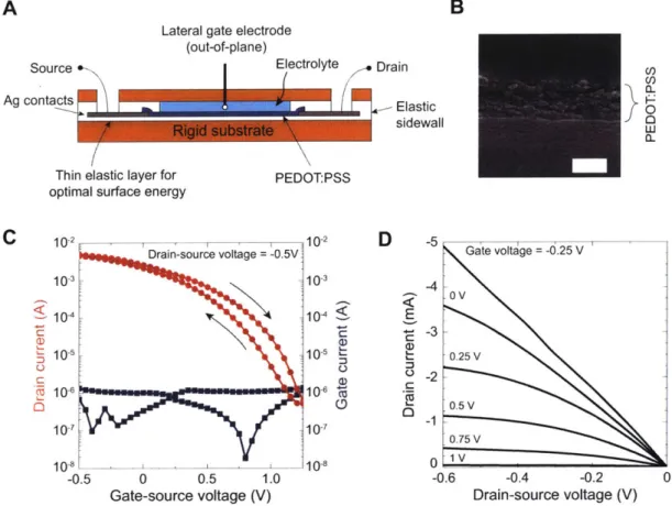
mechani-cal stress. This reaction is enabled by a network of sensors and actuation mechanisms part of their broader sensorimotor network that are seamlessly connected inside this small insect. Integrating elements of sensing with processors and actuators within single composites opens up a route to autonomous sensory composites inspired by nature. Motivated by this, we describe a monolithic integration of strain sensitive elements with an organic electrochemical transistor (OECT) based amplifier and elec-trochromic pixels. A mechanical stimulus is picked up by our strain sensor, amplified electrically by a single-stage amplifier and the transparency is modulated in the op-tical actuator, all within a fully-printed composite powered by 1.5 V.
3.1
Fabrication of sensory composites
In emerging applications that demand sensorimotor analogues, such as in robotics and electronic skins38,3 9, laminates of separately-made high performance sensors40 Contents of this chapter are adapted with permission from - S. Sundaram, Z. Jiang, P. Sitthi-Amorn, D. S. Kim, M. A. Baldo, W. Matusik, "3D-printed autonomous sensory composites", Adv.
Mater. Technol., 2, 1600257 (2017). https: //doi. org/10.1002/admt.201600257 [Copyright John
Golden Tortoise Beetle
Charidotella sexpunctata, Charidotella egregia etc.
Reflective exoskeleton Transparent exoskeleton
Figure 3-1: Golden Tortoise Beetle. Insect like the Golden tortoise beetle can modulate the transparency of their exoskeleton. In its default state, the beetle has a reflective golden shell. When disturbed, the beetle can drain fluid from its exoskeleton and appears red. Image credit: Ken Sproule
and external processors manufactured using several techniques have been used. This progress has been enabled by advances in stretchable materials 41-43 and ultralight
organic electronics'. Solution processed and printable designs have also emerged from the need for low-cost, large-area manufacturing, 27,46-51 in parallel inspiring our
work. Most current approaches to fabricate sensory composites rely on the external assembly of individual components produced from multiple processes, often limiting topology and density.
New additive manufacturing techniques enable the rapid creation of functional parts made of advanced materials in complex shapes1 5,52 with multidimensional
con-trol53. However, 3D-printing is nascent and few functional electronics have been
demonstrated so far. Strain sensors2 1, quantum dot light-emitting diodes20 and
pas-sive components have been 3D-printed but demonstrations of active circuits and large integrations of elements are still missing.
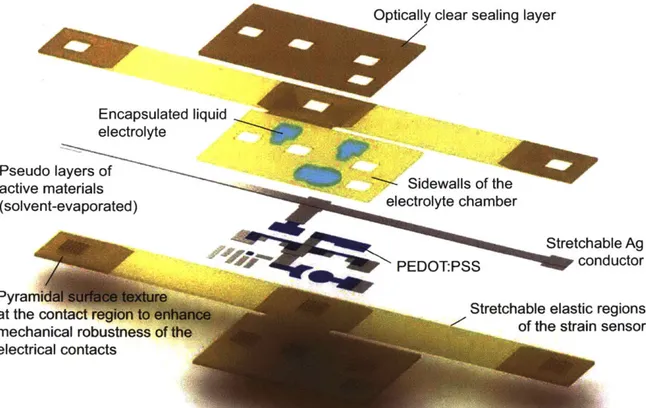
We present a low-temperature additive manufacturing process to achieve an in-tegration of strain sensitive elements, organic amplifiers and electrochromic elements using the integration scheme shown in Fig. 3-2. The solid supporting matrix consists of UV curable rigid (RIG) and elastic (ELA) layers. The strain sensor is defined in
the ELA regions and the amplifier and the electrochromic pixel are written on to the RIG matrix. RIG (elastic modulus ~ 637.76 MPa) and ELA (elastic modulus
678.5 kPa) span three orders of magnitude in stiffness, as shown in Fig. 3-3.
The RIG and ELA UV curable polymer inks are printed simultaneously using the heated printhead to form the substrate layers, which are 700 pm high including the pyramidal contact regions - using the interleaving technique. When the functional inks, PEDOT:PSS and silver ink, are being printed, the heater passes are activated to evaporate the solvent every two layers. At this stage, the ceramic heater moves over the regions containing solvents and traverses back and forth for 10 cycles with the air pump turned on/off automatically, taking -1 min in total. This rapid heating cycle does not seem to have any detrimental effect on the material properties of the underlying substrate since only small regions of the uppermost print layers are exposed to hot air at any time. When silver ink is printed, the patterns made with the nearly transparent silver ink turn white-silver in appearance, signaling formation of silver nanoparticles and the completion of liquid evaporation. The sidewall layers, which are printed next, contain both the rigid and elastic polymers, which are printed using the same settings as the substrate regions. The electrolyte is printed into the wells defined in the elastic material. The print is then sealed with a 500 pm thick rigid capping layer. At the completion of printing, the two strain sensor arms of the print are 1 mm thick in total and the rigid electrical region is 1.5 mm thick. The devices were made thick to demonstrate the ability to print thick composites, showing potential for printing complete functional parts. We will now look at the properties of the individual components in detail.
3.2
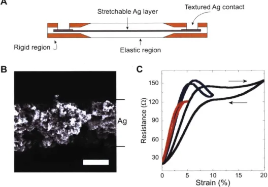
Printed strain sensor
The strain sensor consists of 3 different materials, each with a specific purpose. The RIG layers form the rigid electrical contacts, while the ELA is the stretchable region containing the active material (silver trace), as shown in Fig. 3-4A. The sensors are designed such that the contacts are rigid ensuring that the contacts are unaffected