READ THESE TERMS AND CONDITIONS CAREFULLY BEFORE USING THIS WEBSITE. https://nrc-publications.canada.ca/eng/copyright
Vous avez des questions? Nous pouvons vous aider. Pour communiquer directement avec un auteur, consultez la première page de la revue dans laquelle son article a été publié afin de trouver ses coordonnées. Si vous n’arrivez pas à les repérer, communiquez avec nous à [email protected].
Questions? Contact the NRC Publications Archive team at
[email protected]. If you wish to email the authors directly, please see the first page of the publication for their contact information.
NRC Publications Archive
Archives des publications du CNRC
This publication could be one of several versions: author’s original, accepted manuscript or the publisher’s version. / La version de cette publication peut être l’une des suivantes : la version prépublication de l’auteur, la version acceptée du manuscrit ou la version de l’éditeur.
Access and use of this website and the material on it are subject to the Terms and Conditions set forth at
Representing Architectural Evolution
Erdogmus, Hakan
https://publications-cnrc.canada.ca/fra/droits
L’accès à ce site Web et l’utilisation de son contenu sont assujettis aux conditions présentées dans le site LISEZ CES CONDITIONS ATTENTIVEMENT AVANT D’UTILISER CE SITE WEB.
NRC Publications Record / Notice d'Archives des publications de CNRC:
https://nrc-publications.canada.ca/eng/view/object/?id=838dee97-71b7-4a24-9af9-c711b2d1a3a6 https://publications-cnrc.canada.ca/fra/voir/objet/?id=838dee97-71b7-4a24-9af9-c711b2d1a3a6
Representing Architectural Evolution
Hakan Erdogmus
Institute for Information Technology, National Research Council
Montreal Road, Building M-50, Ottawa, Ontario, Canada K1A 0R6
[email protected]
Abstract
Software engineers informally use block dia-grams with boxes and lines to express system architectures. Diagrammatic representations of this type are also found in many specifi-cation techniques. However, rarely are archi-tectural documents containing such represen-tations systematically maintained; as a system evolves, architectural documents become obso-lete, and the design history of the system is ul-timately lost. Additionally, box-and-line rep-resentations used in these documents do not possess a precise semantics invariant across the different techniques that rely on them. This pa-per addresses expression of system evolution at the architectural level based on a formal model of box-and-line diagrams. The formal model (a) provides semantic uniformity and precision; and (b) allows evolutionary steps to be repre-sented as structural transformations. Interest-ing classes of such transformations are charac-terized in terms of the underlying operators. With these tools, the architectural evolution of a system is captured as a directed acyclic graph of baselines, where each baseline con-sists of a system of box-and-line diagrams, and is mapped to a successor baseline by a set of structural transformations. It is also shown how familiar design concepts—such as exten-sion, abstraction, and structural refinement— can be formalized in simple terms within the framework developed.
1
Introduction
Block diagrams with boxes and lines are com-monly used in software engineering to infor-mally express system architectures. Numerous specification and modeling techniques for de-signing distributed systems also rely on them; examples include ROOM [15], SDL [14],
Mod-echart [7], DSL [19], and Lotos [6].
More-over, this type of system structuring is im-plicit in software architecture description lan-guages [17]—such as Wright [1], Aesop [3], Uni-con [16], Rapide [8], and ACME [4]—as well as their predecessors, module description lan-guages [12]. The common aspect of all of these techniques is their adoption of the familiar
component-connection-configuration paradigm
[9], whereby large systems are constructed by interconnecting smaller subsystems. This paradigm focuses on what may be referred to as runtime architectures, such as expressed by an object or module connection (interaction) diagram, rather than on source-code architec-tures, such as expressed by a UML1 class
dia-gram [13].
Although they are quite intuitive, box-and-line diagrams do not possess a precise seman-tics uniform across the specification techniques that employ them. The structural semantics is often intertwined with the behavioral seman-tics of the particular technique used. Conse-quently, architectural documents written in dif-ferent specification techniques are difficult to share.
A common semantic model is a good start,
1
UML is a trademark of Rational Software Corporation.
but ignores one important aspect: system evo-lution. Evolution is inevitable since both re-quirements and technology change rapidly. Un-fortunately, architectural documents may, over time, become obsolete; often, they are pro-duced once, or are not maintained systemati-cally. Furthermore, these documents are rarely
put under configuration management.
Con-sequently, the design history of the system is eventually lost. However, this information can be valuable during maintenance, redesign, and future extensions for large and long-lived systems, especially when employee turnover is high. Since keeping track and recording archi-tectural changes may be laborious, automation is desirable. A formal approach supports au-tomation through explicitness, precision, and rigor.
To address system evolution formally at the architectural level, this paper defines a set-theoretic model based on box-and-line dia-grams; introduces an abstract, flexible notion of transformation for these diagrams; and iden-tifies several different kinds of such transforma-tions to express common architectural changes. As such, a general framework emerges in which to represent the architectural evolution of a system at a high level through a sequence of purely structural transformations. The frame-work allows the formalization of familiar design concepts—such as extension, structural refine-ment, and abstraction—in set-theoretic terms. As a motivation, consider the following
ex-ample adapted from Selic et al. [15].
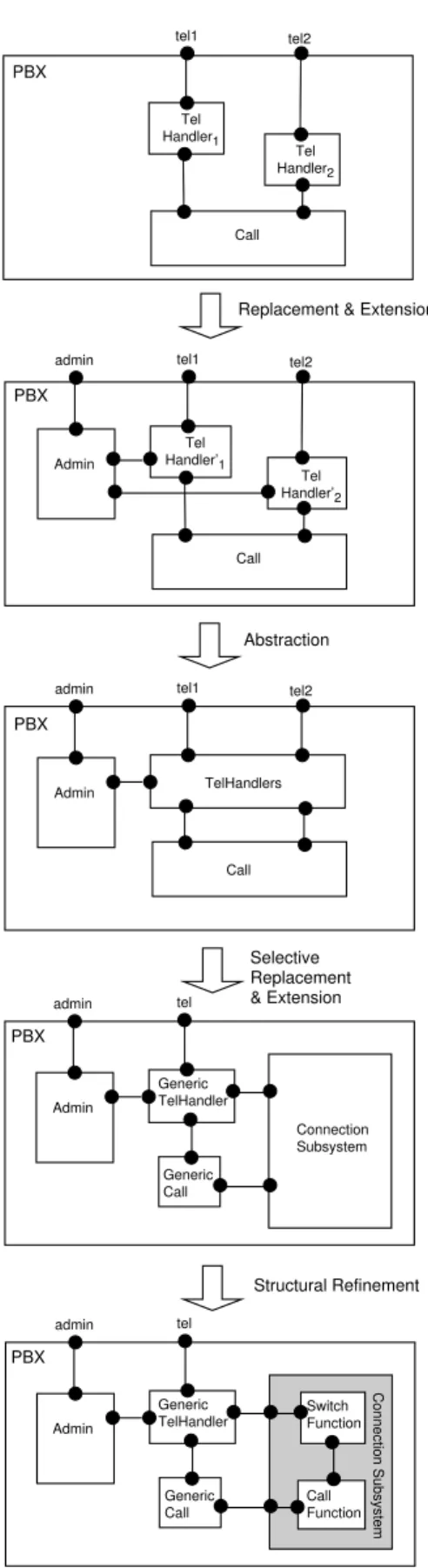
Fig-ure 1 depicts the architectural evolution of a PBX system during its modeling stage. The initial model is very simple: it only considers two users (telephones) and disregards admin-istration functions. The TelHandler compo-nents shields the rest of the system from fu-ture changes to the supported types of
tele-phone equipment. The Call component
en-capsulates the capabilities related to calls. At the next step, the model is extended to include a component Admin for administration func-tions. TelHandler is replaced by an extended version TelHandler′, which can interface with
the administration component. Then the two
TelHandler′ components are abstracted into a
single component, TelHandlers, to be able to later generalize the system to accommodate N
users. Next, the TelHandlers component is
replaced by a generic component
GenericTel-Handler that can can handle up to N users
through a single interface. Similarly, the Call component is replaced by a generic call handler (GenericCall) that can handle several calls at once. At the same time, a connection subsys-tem is added so that the call handler would no longer be concerned with the details of es-tablishing, maintaining, and releasing connec-tions. Finally, the connection subsystem is re-fined into a component that isolates switching capabilities and another that interfaces with the call handler. Thus the evolution of the system from the initial to the final model is recorded as a sequence of box-and-line dia-grams related through conceptual design op-erations (namely, extension, abstraction, struc-tural refinement, and component replacement). This representation contains valuable informa-tion that would otherwise be lost, and helps in the comprehension and communication of the design choices made during the evolution of the system. Apart from being used in model devel-opment to keep track of architectural changes as illustrated in this small example, such rep-resentations can also be used during re-design or re-engineering to communicate and control design decisions. Similarly, they can be used for configuration management of components at a high level in component-based system de-velopment, as supported by emerging compo-nent technologies such as JavaBeans [18]2.
The purely structural view of architecture has its limitations: it does not address all as-pects of architectural abstraction. In partic-ular, functional properties, performance, and reliability concerns are left out. Neither are the underlying design rationales made explicit by this view. Additionally, for some systems, the box-and-line architecture is trivial, or does not convey any useful information about the organization of the system. A purely struc-tural model may be insufficient to relate the
in-tended architecture to the as-implemented
ar-chitecture and to prevent architectural drift. All of these issues are important from the point of view of system evolution, and may be treated in a larger framework. Our treatment is
lim-2
PBX Admin Generic TelHandler Generic Call Call Function Switch Function Connection Subsystem admin tel PBX Admin Generic TelHandler Generic Call admin tel Connection Subsystem PBX Admin TelHandlers Call admin tel1 tel2
PBX
Admin
Tel Handler’1
Call admin tel1 tel2
Tel Handler’2 PBX Tel Handler1 Call tel1 tel2 Tel Handler2
Replacement & Extension
Abstraction
Selective Replacement & Extension
Structural Refinement
Figure 1: Model evolution example.
A
A
AA
AAAAA
AAAAA
AA
AA
AA
A
A
AAA
AAAA
AAA
A
A
A
AAA
AAA
AAA
A’AAA
AAAA
AA
AA
A
AA
AA
Figure 2: A structural transformation.
ited to those aspects that can be addressed by structure alone, and there is much insight to be gained by focusing on the structural aspect.
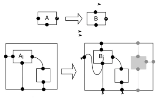
A central concept introduced in the paper is that of a structural transformation. A struc-tural transformation defines a semantic corre-spondence between a source system and a tar-get system through a mapping on their inter-face ports, as shown in Figure 2. The structural transformation does not imply that the two sys-tems provide equivalent external functionalities relative to some behavioral model. It simply states that, under the specified mapping, the system on the right will effectively replace the system on the left, regardless of any variation in the actual overall external functionality. The mapping defines for each interface port of the system on the left, a corresponding interface port of the system on the right such that the se-mantic role played by the image port subsumes the semantic role played by the source port. The transformation does not imply that the ex-ternal functionality of the system on the right subsumes that of the system on the left. This information often cannot be determined based on structure alone, and is meaningful only rela-tive to a behavioral model. The overall external functionality of a system is not simply the sum of its interface ports and its constituent com-ponents. It is the behavioral model that deter-mines the external, or black box, behavior by assigning functionality to the lowest level mod-ules and defining a composition construct to infer the external functionality of a composite module from those of its constituents. This lat-ter subject is addressed by numerous semantic theories of concurrency and programming lan-guages, and is beyond the scope of this paper. The reader is referred to Milner’s seminal work [11] for a classical example.
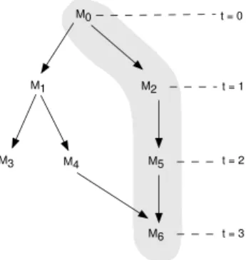
Given the notion of structural transforma-tion, the architectural history of a system can be recorded as a directed acyclic graph (DAG),
M0 t = 0 M2 t = 1 M5 t = 2 M6 t = 3 M1 M4 M3
Figure 3: An evolution graph. The nodes rep-resent different baselines and the arrows repre-sent the deltas between subsequent baselines. The shaded area identifies a path in the (di-rected acyclic) graph with four evolution steps labeled from t = 0 to t = 3.
where each node represents a baseline that con-sists of a system of box-and-line diagrams. A baseline is mapped to its successor by a set of structural transformations. Thus the transfor-mations represent deltas that establish seman-tic correspondences between neighboring pairs of baselines along a given path in the evolution graph (Figure 3). The evolution graph is usu-ally a tree. It becomes a DAG if two baselines on different paths are merged into a common baseline in their subsequent versions.
The model has a deficiency. Although the structural transformations defined allow merg-ing of interfaces in subsystems, they do not per-mit interface splitting or refinement. Interface refinement is common practice, but is difficult to formalize as a homomorphic transformation. Further structuring of interfaces is neither suf-ficient nor necessary to formalize the concept since interface refinement affects connections in a context-dependent way. The affected connec-tions have to be specified in every context in which the interface-refined subsystem appears. This in turn makes interface refinement a prob-lematic operation. The treatment of interface refinement is planned as future work, and as such, is not addressed in this paper. See Sec-tion 6 for further discussion.
The rest of the paper is organized as follows: In Section 2, the general concept of a module based on box-and-line structures and the asso-ciated formal model are introduced. Section 3
discusses structural relations on modules and states a fundamental closure property of these relations. The notion of structural transforma-tion is introduced in this sectransforma-tion. Sectransforma-tion 4 defines a set of relevant operators on box-and-line structures. Each of these operators under-lies a particular class of structural transforma-tions. Representation of architectural histories is addressed in Section 5, where some of the operators introduced in Section 4 are related to familiar design concepts. A summary and discussion can be found in Section 6.
2
Module Systems
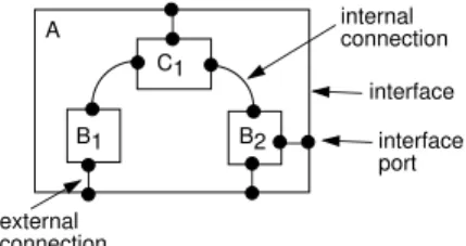
The term module refers to the basic unit of ab-straction used to construct systems. We depict the structure of a module in terms of an enclos-ing box, inside of which may be a set of boxes interconnected by solid lines, as illustrated in Figure 4. Such diagrams are commonly referred to as box-and-line or block diagrams.
A module has two associated views:
1. The black box view specifies the external
structure of the module, and involves a
fixed interface. In a box-and-line diagram, the interface is indicated by the enclosing box.
2. The clear box view specifies the
inter-nal structure of the module in terms of a
collection of instances of other modules, called components. The components are interconnected in a fixed configuration. In a box-and-line diagram, components are represented by boxes inside an enclosing box, and connections by solid lines be-tween the inner boxes.
2.1
Attributes of a Module
The most fundamental attribute of a module is its interface. The interface consists of a set of
ports which collectively specify the boundary
through which an instance of that module can be interconnected with other modules to form a larger system. Ports are depicted by dark circles in box-and-line diagrams.
Each component of a module is specified as an instance Ci of some other module C. Then
internal connection interface interface port external connection A C1 B1 B2
Figure 4: The box-and-line structure of a mod-ule A. Interface ports are distinguished from one another by their relative placement on module boundaries.
C is said to be the type of the component Ci,
written Typ(Ci) = C.
Some components are connected to each other through their interface ports, while oth-ers may be connected to the interface ports of the enclosing module. We write p.Ci `M q.Dj
if in module M , the interface port p of a com-ponent Ci is connected to the interface port
q of another component Dj. Such a
connec-tion is called an internal connecconnec-tion. The inter-nal connection relation `M is symmetric; hence
p.Ci`M q.Dj implies q.Dj `M p.Ci. We write
p aM q.Dj if the interface port q of a
compo-nent Dj is connected to the interface port p of
the enclosing module M . Such a connection is called an external connection.
Figure 4 illustrates these concepts.
2.2
Formal Model
A module system M is a triple hMods, Ports, Str i, where
• Mods is a set of module names; • Ports is a set of port names; and
• for each module M ∈ Mods, Str (M ) spec-ifies the architecture of M in terms of a
box-and-line structure over M.
A box-and-line structure (or bl-structure) S over a module system M is a quadruple hIntfS, CmpsS, `S, aSi, where
• IntfS is the interface of S;
• CmpsS is the set of components of S; • `S is the set of internal connections of S;
and
• aS is the set of external connections of S.
We have
• IntfS ⊆ Ports is a finite set;
• CmpsS ⊆ Mods × Nat is a finite set where
each component Ci (i ∈ Nat) is an
in-stance of some module C ∈ Mods;
• `S ⊆ (Ports × CmpsS) × (Ports × CmpsS)
is a finite, symmetric, irreflexive relation such that p.Ci `S q.Dj implies p ∈ IntfC
and q ∈ IntfD.
• aS ⊆ IntfS×(Ports ×CmpsS) is a relation
such that p aS q.Dj implies q ∈ IntfD.
For a module M ∈ Mods, we often say “the interface of M ” to mean “the interface of
Str (M ),” and similarly for the components and
the sets of connections of M . By abuse of nota-tion, Mods and M will be used interchangeably: M ∈ M should be understood as M ∈ Mods. Accordingly, given Str (M ) = S, we simply write IntfM, CmpsM, `M, and aM to denote
IntfStr(M ), CmpsStr(M ), `Str(M ), and aStr(M ),
respectively.
A module N is a submodule of another mod-ule M , written N < M , if M has a component Ni(of type N ). The transitive closure of the
re-lation < is called the dependence rere-lation, and is denoted by <∗. For a module system to be
well defined, the graph of the dependence re-lation must be free of cycles. This property is assumed throughout the paper.
A module M is called a leaf module if
CmpsM = ∅. Hence the internal structure of
a leaf module in unspecified. A leaf module oc-cupies a leaf node in the dependence graph of a module system.
3
Structural Relations
To support the formal model introduced in Sec-tion 2, a proper semantic equivalence relaSec-tion must be defined on modules. It would not be very useful to semantically equate two mod-ules if and only if they are identical. A weaker concept is needed. Then what kind of rela-tion would be suitable to decide whether there is any practical reason to distinguish between two given modules in a module system based
AA
AA
AAAAAA
AAA
AA
AA
A
AA
AA
AA
AA
AA
AAA
AAA
AAAA
AAA
AAA
AA
AA
AA
AA
A
A
A1 B0 A’3 B’1 C1 Figure 5: A bl-homomorphism. on their structures alone? An isomorphism on bl-structures underlies such a relation. We will refer to this isomorphism as a bl-isomorphism. The notion gives rise to the sought semantic relation when an extra property is satisfied.A weaker, but independently useful
con-cept is that of a bl-homomorphism. A
bl-homomorphism maps the bl-structure of a module to that of a second module, while pre-serving both the internal and the external con-figuration of the first, as illustrated in Figure 5. A isomorphism is simply a bi-directional bl-homomorphism in which the underlying map-pings are reversible.
The notion of a bl-homomorphism can be used to express the fact that a given module may structurally evolve into another module such that for each interface port, component, and connection of the first module, the sec-ond module has a correspsec-onding interface port, component, and connection, respectively, with a similar (or larger) semantic role.
However, a mapping of internal structures (components, internal ports, and connections) is in general not necessary to represent the architectural evolution of a module. A map-ping of its external structure (interface ports) is sufficient, since the internal structure can be subjected to arbitrary changes as the module evolves, whereas a certain degree of semantic consistency should be maintained in the exter-nal structure. The notion of structural
trans-formation captures this less restricted form of
evolution. By a set of such transformations, it is possible to represent a one-step evolution of a system of modules. We will refer to a set of structural transformations as a transform
rela-tion.
If a module evolves through a sequence of ar-bitrary changes to its internal structure, then
all modules that depend on that module will also evolve simultaneously. This principle is referred to as substitutivity. Therefore, the implied architectural evolution of the depen-dent modules can also be captured by a trans-form relation. However rather than being arbi-trary, the changes to the internal structure of these dependent modules are dictated by the changes to the internal structure of the mod-ules on which they depend. Here the notion of bl-homomorphism comes into play: the struc-tural transformation of one dependent module to another is guided by an underlying (surjec-tive) bl-homomorphism.
3.1
Structural Homomorphisms
Given two bl-structures S and R, a triple hσ, γ, Σi is called a bl-homomorphism from S to R if
1. σ: IntfS −→ IntfR is a function from the interface of S to the interface of R; 2. γ: CmpsS −→ CmpsR is a function from
the components of S to the components of R;
3. Σ def= {σCi | Ci ∈ CmpsS} is a set of
functions such that for the component Ci
of S, the function σCi: IntfTyp(Ci) −→
IntfTyp(γ(Ci))maps an interface port of the
type of Ci to an interface port of the type
of γ(Ci) in R; and
4. the homomorphism preserves the connec-tions:
• p.Ci`S q.Dj implies
σCi(p).γ(Ci) `RσDj(q).γ(Dj)
• p aS q.Dj implies
σ(p) aRσDj(q).γ(Dj).
A bl-homomorphism is illustrated in Fig-ure 5. In the figFig-ure, the mapping γ is color coded and the mapping σ is indicated by dashed arrows. The mappings in Σ are not shown, but can be inferred from the physical placement of the components’ interface ports.
The mathematical concept of
bl-homomorphism is fundamental. It under-lies the design concept of structural inheritance
(without component exclusion), such as imple-mented in the ROOM [15] technique, whereby a module is allowed to inherit its structure from another module and extend it if necessary.
3.2
A Structural Equivalence for
Modules
The definition in the previous subsection gives rise to a bl-isomorphism if all the functions in-volved (σ, γ, and the σCi of Σ) are bijective
(one-to-one and surjective). The isomorphism preserves component types only if the func-tion γ preserves component types—that is if
Typ(γ(Ci)) = C, for every Ci∈ CmpsS.
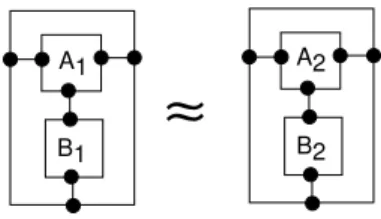
Now we can define a semantic relation on structures based on the notion of bl-isomorphism. Denote this relation by ≈. For two bl-structures S and R such that CmpsS6= ∅ 6= CmpsR, we write S ≈ R if S and R are re-lated by a bl-isomorphism that preserves com-ponent types. Note that ≈ is an equivalence (reflexive, transitive, and symmetric), and as such, can suitably play the role of a seman-tic relation for bl-structures. It is illustrated in Figure 6. What ≈ essentially accomplishes is to abstract away from module and interface port names as well as component indices.
The relation ≈ is considered to be the strongest of all interesting semantic relations on bl-structures. Thus if two bl-structures are related by this relation, not only their struc-tures are isomorphic, but also they should pro-vide exactly the same external functionality. Therefore, if Str (M ) ≈ Str(N), then M and N are considered to be practically indistinguish-able, and the two are safely interchangeable in all contexts. Note, however, that Str (M ) 6≈
Str (N ) does not necessarily imply that M and
N have different external functionalities. So ≈-equivalence is a sufficient, but not a necessary, condition for behavioral equivalence.
By stipulating that CmpsS 6= ∅ and
CmpsR 6= ∅, the possibility of ≈ equating two
different leaf modules is avoided.
3.3
Transform Relations
The ability of a module to undergo an archi-tectural change at a point during its lifetime is
A1
B1
A2
B2
≈
Figure 6: Two ≈-equivalent bl-structures.
formalized by the notion of structural transfor-mation. The architectural change may repre-sent a specialization, a (structural) refinement, an extension, or some other conceptual design operation.
Given two module system M and N, a
(structural) transformation over M × N is a
triple hM, σ, N i, where M ∈ M, N ∈ N and σ: IntfM −→ IntfN is a function which asso-ciates an interface port of N with every inter-face port of M .
A set à of transformations over M × N is called a transform relation over M × N. The
shorthand notation M Ã N is used to meanσ
hM, σ, N i ∈ Ã, and is read as “Ã transforms
M to N under σ.” When à is clear from
the context, we simply say “M transforms, or evolves, to N under σ.”
Transform relations can be used to represent the architectural evolution of an entire system in terms of structural transformations across sets of modules. This subject will be discussed in Section 5.
Consider a base transform relation à which identifies the transformations that are by some external means known to be semantically sound. That is, if M à N , it is given thatσ for each interface port p of M , the correspond-ing interface port σ(p) of N is locally capa-ble of assuming a similar semantic role as p in any context in which N replaces M . Here we leave the exact meaning of the term “simi-lar” uninterpreted since the concept varies for each different specification technique. In gen-eral, it refers to some kind of interface or port type compatibility. The key point is that the base relation captures some arbitrary changes to the structure of a system, and assumes that the semantic soundness of these changes is es-tablished outside the model.
may affect other parts of the the system due to interdependencies between the parts. If a module evolves through a sequence of trans-formations, then all modules that depend on that module should also evolve simultaneously through a similar sequence of transformations. This principle is known as substitutivity. More precisely, substitutivity states that if a sur-jective bl-homomorphism3 relates two modules
such that each component in the source module transforms to the homomorphic image of that component in the target module, then the first module transforms to the second.
The substitutivity principle is illustrated in Figure 7. As an example, suppose module M has a component of type C (i.e., M depends on C) and C transforms to D. Replace that component by a component of type D. Then M transforms to the module resulting from the substitution of D for C in M .
Given a base transform relation Ã, a min-imal transform relation always exists that (1) contains Ã, and (2) is closed under substitu-tivity. Let Ã∗ denote this relation. Note that
Ã∗ is unique if every module in M is unique
up to the equivalence ≈ (for every M, N ∈ M, M 6= N implies Str (M ) 6≈ Str(N)). Thus, Ã∗,
or the substitutive closure of à can be defined as the smallest relation that satisfies the follow-ing properties:
1. MÃ N implies Mσ Ãσ∗N (Ã∗contains Ã).
2. if
2.1 CmpsM 6= ∅ (M is a non-leaf
mod-ule), and
2.2 there exists a surjective
bl-homomorphism hσ, γ, Σi from M to N such that CÃσCi∗Typ(γ(Ci)) for
every component Ci∈ CmpsM
then MÃσ∗N .
Note that by property 2, Str (M ) ≈ Str(N) implies MÃσ∗N
σ−1
Ã∗M , for some σ : IntfM −→
IntfN.
3
A bl-homomorphism is surjective if all the map-pings involved (the functions σ and γ, and the functions in Σ) are surjective.
AAAA
AAAA
A
A
AAA
AAA
AAA
AAA
A B a) Ai Ci Bj Ci A B b) Ai Ci Bj CiAAAA
AAAA
A
A
AA
AA
AAA
AAA
A
A
AA
AA
AA
AA
AAAA
AA
AA
A
A
Figure 7: Substitution.4
Structural Operations
We depart from the premise that the high-level architecture of a system often does not evolve in a completely arbitrary and chaotic
way. Certain transformational patterns are
applied over and over again. Although this
premise is not validated by hard empirical evi-dence, we believe that most software designers would agree with it. In other words, the evolu-tionary changes are usually guided by well de-fined operators that transform the structure of the parts to which they are applied in particu-lar ways. It is not sufficient for such operators to return a new structure. Their application must also return a mapping which specifies a semantic correspondence between the old and the new structures.
Formally, a structural operator is a partial function on bl-structures (it is more convenient to define the notion on bl-structures than on modules). When such an operator is applied to a bl-structure that satisfies the operator’s pre-conditions, it returns a new bl-structure over the same module system, together with a se-mantic correspondence function from the inter-face ports of the operand to those of the result-ing bl-structure.
a bl-structure over M. Then op(S) returns a pair hR, σi where R is a bl-structure over M and σ: IntfS −→ IntfR is a function from the
interface of S to the interface of R. The func-tion σ maps every interface port of the operand S to a corresponding interface port of R.
A transformation MÃ N is based on a struc-σ tural operator op if op(Str (M )) = hR, σi such that Str (N ) ≈ R. When this property holds, we say that MÃ N via op. Note that ≈ is usedσ instead of plain equality in this definition.
Next examples of some structural operators are given. All of these operators are intuitive. The formal definitions are omitted here; they have been included in a previous technical re-port [2]. It is possible to define the structural operators in a set-theoretic or in a graph gram-mar formalism. The set-theoretic approach is used here.
In what follows, each operator’s syntactic form is specified as op[P1, . . . , Pn], where op
is the name of the operator, and the Pi are
the secondary parameters involved (besides the operand). Thus the application of the operator to a bl-structure S (the operand) is denoted by
op[P1, . . . , Pn](S).
4.1
Homomorphic Operations
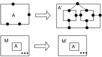
Two structural operators, namely substitution and extension have particular importance be-cause they induce bl-homomorphisms. When an arbitrary sequence of these fundamental op-erators are applied to a given bl-structure, the resulting bl-structure turns out to be homomor-phic to the starting bl-structure. An example is provided in Figure 8. If the application se-quence consists of only substitution operations, the induced bl-homomorphism is surjective. If it consists only of extension operations, then in the induced homomorphism the function γ and the functions in Σ are identity functions.
4.1.1 Substitution
Subst[Ci, D, δ]
Substitution involves replacing a component of a given bl-structure with an instance of some other module. In order to apply this opera-tor to a bl-structure S, the component Ci ∈
CmpsS to be replaced, the module D
(replace-AA AA AA A A A AA AA
AAAAAAAAAAAAAAAAA A A A A A A AAA AA AA AA AAAAAAAAAAAAA A A AA AA AA AAA AAA AAAAAAAAAAAAAAAAAA AA AA Ai Bj A A AA AA
AAAAAAAAAAAAAAAAAAAAAAA
A AAAAAA B
AAAAAAAAAA A A AA AA
Figure 8: bl-homomorphism resulting from
substitution followed by an extension. In the substitution, the replaced component is Aiand
the replacement module is B. The extension operation is indicated by the grey areas. ment module) whose instance is to replace Ci
in S, and a function δ: IntfC −→ IntfD must be specified.
The result of the substitution is a new bl-structure in which Ci is replaced by some
in-stance Dj of D according to the interface
map-ping δ such that Dj6∈ CmpsS (so that the new
instance does not clash with other components of type D in S.) The interface of the operand S is mapped to the interface of the new module by the identity mapping on IntfS. Substitution
was illustrated in Figure 7.
In the bl-homomorphism induced by the sub-stitution, σ is the identity function on the operand, γ is such that γ(Xi) = Xi if Xi6= Ci
and γ(Ci) = Dj otherwise.
The substitution operator underlies the sub-stitutivity principle. The substitutive closure of a transform relation can be defined in terms of this operator: a transform relation is closed under substitution (or with respect to the substitutivity property) if a module N trans-forms to another module M whenever the bl-structure of N can be obtained from that of M (up to ≈) through a sequence of substitutions such that the precondition CÃ D is satisfiedδ for each operation in the sequence.
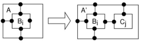
4.1.2 Extension
Extend [Intf+, Cmps+, `+, a+]
Extension involves adding new interface ports, components, and connections to a given
A Bi A’ Bi Cj Figure 9: Extension.
bl-structure. In order to apply an extension op-erator to a bl-structure S, the sets of new inter-face ports Intf+, components Cmps+, internal connections `+, and external components a+ must be specified. The resulting bl-structure is obtained by taking the pairwise union of the old and new sets.
The new connections may involve the inter-face ports of both the old and the new com-ponents, as well as the ports of both the new and the old interface. For the operator to be applicable to an operand S, Intf+, Cmps+, `+, and a+ should be such that the resulting bl-structure is well defined.
As is the case for substitution, the interface of the operand S is mapped to the interface of the extended module by the identity mapping on IntfS. Extension is illustrated in Figure 9.
In the bl-homomorphism induced by the ex-tension, all of the mappings involved equal the identity functions on the domains of those map-pings. Extension is equivalent to structural in-heritance without component exclusion [15].
4.2
Reversible Operations
Substitution and extension are not the only kinds of structural operations to be considered. It is possible to identify several other kinds of operators. Those discussed in this subsection should ideally preserve the external functional-ity of the modules to which they are applied, although this is not always guaranteed in every behavioral model.
All of these additional operators are re-versible, in that if M Ã N via such an oper-σ ator op, then N Ã M via an inverse operatorσ
op−1. As in extension and substitution, the
re-sulting function σ is the identity mapping on the interface of the operand.
clean
extend
Figure 10: Clean operation.
Aj A
peel wrap
Figure 11: Wrap and peel operations.
4.2.1 Clean
Clean
The clean operator removes a non-essential component from a bl-structure, as shown in Figure 10. A component is essential if it is directly or indirectly connected to an interface port of the bl-structure. Formally, Ci∈ CmpsS
is an essential component of S iff p aS q.Cifor
some q ∈ IntfC, p ∈ IntfS, or p.Ci`S q.Dj for
some p ∈ IntfC, Dj ∈ CmpsS, q ∈ IntfD such
that Dj is an essential component of S.
The inverse of a clean operation that removes component Ci from a module is an extension
operation which adds a loose component of the same type to the result of the clean operation.
4.2.2 Wrap and Peel
Wrap, Peel
The wrap operator encapsulates a bl-structure within another bl-bl-structure as the sole component of the latter. Every interface port of the wrapped component is connected to a distinct interface port of the wrapper module. The inverse of this operation is the peel op-erator, which extracts the wrapped component from a wrapper module by removing the lat-ter’s outer shell.
These two operators are illustrated in Fig-ure 11.
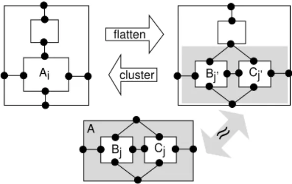
4.2.3 Flatten and Cluster
Flatten[Ci], Cluster [X, M ]
The flatten operator unravels a bl-structure S with respect to a given component Ci. In
the resulting bl-structure, the component Ci is
replaced by C’s own components and
connec-tions. For every component Dj of C, a new
component Dj′ is added to S such that the
in-stance Dj′ does not clash with any previously
existing instance of D in S. The internal con-nections of the resulting bl-structure, say R, is set such that:
• if p.Dj`Cq.Ek then p.Dj′ `Rq.Ek′;
• if p aC q.Dj and p.Ci `S r.Ek then
q.Dj′ `Rr.Ek; and
• if p aC q.Dj and r aS p.Ci then r aR
q.Dj′.
This process corresponds to removing the outer shell of Ciwithin S, thereby exposing its
inter-nal structure to S.
For a flatten operator to be applicable, C must be a non-leaf module.
The inverse of this operator is called
clus-ter. Clustering factors out a subset X of a
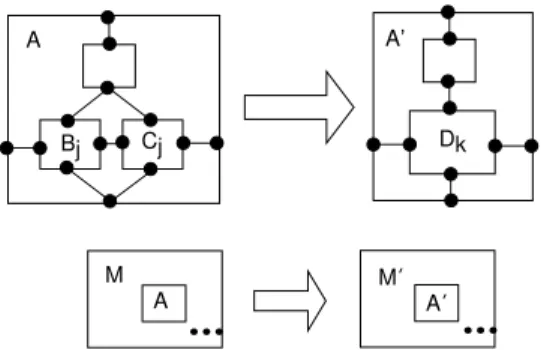
bl-structure’s components by encapsulating X within an instance of a proper module M . Then M is called the abstraction module. The cluster and flatten operators are illustrated in Figure 12.
The cluster operation has the following pre-condition: Str (M ) must be ≈-equivalent to the bl-structure given rise by the subset X (in the context of the enclosing bl-structure to which the cluster operator is applied). We require the abstraction module M to be explicitly speci-fied, although such a module can automatically be constructed from X.
5
Architectural Histories
It is possible to represent the architectural his-tory of an evolving system as a DAG, as shown in Figure 3. We call such a graph an evolution
graph.
Each node of an evolution graph denotes a
baseline of the underlying system. A baseline
is self-contained in that it does not contain ref-erences to objects outside it. As such it exists
Bj Cj A Ai Bj’ Cj’ flatten cluster
≈
Figure 12: Flatten and cluster operations. The shaded inner box on the right represents the bl-structure associated with the subset {Bj′, Cj′}
of the enclosing bl-structure. A is the underly-ing abstraction module.
independent of other baselines. Conceptually, a baseline represents a distinct version of the system at a given point in time, or as a variant of an ancestor baseline.
A branch in the graph defines an evolution
step. Each evolution step maps a source
base-line to a successor, and as such represents a
delta of the source baseline.
The rest of this section demonstrates how the previously developed concepts can be used to specify this kind of system progression in terms of baselines and evolution steps.
5.1
Baselines
and
Evolution
Steps
Suppose each baseline is specified in terms of a module system. With this in mind, let Mt
denote the module system associated with the baseline t. A path in the evolution graph can then be represented as a sequence:
M0 1
⇒ M1
2
⇒ · · ·⇒ Mn n
where⇒ represents the tt thevolution step along
the path. When step ⇒ is applied to baselinet Mt−1, the successor baseline Mtis obtained.
By abuse of notation, we will use conven-tional set operators (∪, /, ⊆) on module sys-tems. As a general rule, the set operator should be though of as being applied to the sets of modules of the operands.
• a module system M+ of introduced
mod-ules,
• a module system M− ⊆ M
t−1 of retired
modules, and
• a base transform relation à over (Mt−1/M−) × M+, where M
σ
à M′
means that module M of baseline t − 1 is transformed to module M′ in baseline t.
Then module M′is referred to as the next
version of module M .
The baseline Mt−1is called the source baseline,
and Mt is called the target baseline.
In addition, each evolution step⇒ must sat-t isfy the following properties:
1. The next version of a module is unique when it exists: M Ã Mσ ′ and M Ã Mσ ′′ implies M′= M′′.
2. The target baseline includes all introduced modules and excludes all retired modules: Mt⊇ (Mt−1∪ M+)/M−.
The base transform relation à defines the modules which are directly updated by the evo-lution step. Only those changes that cannot be inferred through the substitutivity principle are included in this relation.
The set of introduced modules, M+, mainly
contains the new versions of those modules in the source baseline (Mt−1) that are to be
up-dated by à for inclusion in the target baseline (Mt). It may also contain brand new top-level
modules to be introduced for the first time in the target baseline along the current path. The descendants (with respect to the dependence relation <) of these modules are also included for completeness purposes.
The set of retired modules, M−, contains
those modules that are to be retired in the tar-get baseline. For the tartar-get baseline to be well defined, none of its modules may depend on a retired module.
With these constraints, the substitutive clo-sure of à is a transform relation over Mt−1×
Mt. This relation determines the next version
in the target baseline of a given module of the source baseline, provided the module changes
version. Thus for M ∈ Mt−1 and N ∈ Mt,
MÃσ∗N means M changes version from
base-line t−1 to basebase-line t. In this case either MÃNσ or N is obtained from M through a successive substitution of M ’s components whose versions change, by the instances of the next versions of these components.
5.2
Versioning
A version number is attached to each module to keep track of its evolution along a given path in the evolution graph. A versioned module is denoted by Mv, where v is the version
num-ber, and M is the unique name of the module. Version numbers are independent of baseline indices, so that if Mv∈ M
t, it is often the case
that t 6= v.
If a module does not change version from one baseline to the next, its version number remains the same. Otherwise, it is incremented. We as-sume that version numbers start at 0 for each new module name, and is incremented by one every time the module evolves into a new ver-sion.
Each baseline contains at most one version of a given module: Mv, Mw∈ M
timplies v = w.
Thus at step t, a module Mv of baseline t − 1
may evolve into a unique new version Mv+1 in
baseline t.
In general, the system M+ associated with
step t may contain three types of modules:
a. Mv+1 where Mv ∈ M
t−1: these are new
modules not in the source baseline, but each represents a new version of some module in the source baseline. For each of these modules, the base transform re-lation associated with step t must contain an entry Mv σ
à Mv+1.
b. Mvwhere Mv∈ M
t−1: these are
submod-ules of some module in M+, and do not
ap-pear in the domain of the base transform relation Ã. They are included in M+ to
preserve well-definedness of M+. c. M0 where (∀v)(Mv 6∈ M
t−1): these
mod-ules are either new top-level modmod-ules, or they are descendants (submodules) of some module in M+. In either case, the
name M is introduced for the first time along the current path; hence the version
number is 0. These modules do not appear in the base transform relation à either.
5.3
Execution of an Evolution
Step
Evolution steps act as deltas on baselines. Thus given a path in the evolution graph, baseline t is obtained by executing the evolution step t on baseline t − 1. The execution algorithm guar-antees that if M changes version from baseline t − 1 to t, then every module that depends on M also changes version accordingly. Hence if
Mv σ
Ã∗Mv+1and Mv< Nw(Mvis a
submod-ule of Nw) for some Nw∈ M
t−1, then Mtmust
contain a module Nw+1such that Nw δ
Ã∗Nw+1
for some δ. If Nw is not in the domain of Ã
then δ is the identity function on IntfNw;
oth-erwise it equals β where Nw β
Ã∗Nw+1. The
module Nw+1is the next version of Nwin
base-line t. It is obtained by substituting in Nw an
instance of Mv+1 for every instance of Mv.
The application algorithm first initializes Mt
to M+, and then recursively adds the next
ver-sions of all affected modules in baseline t − 1 that depend on some module in the domain of Ã. After this step, the remaining modules of baseline t − 1 are copied to baseline t provided that they are excluded from M−. These
mod-ules do not change versions in baseline t. Mod-ules in M− are omitted from baseline t.
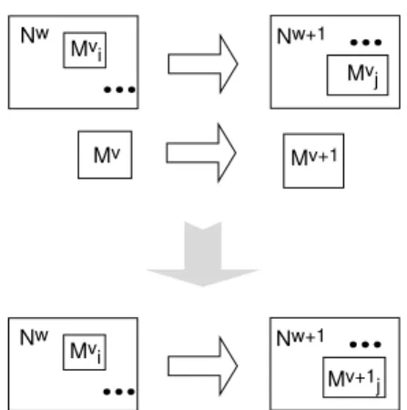
If Mv σ
ÃMv+1, Nw δÃNw+1, and Mv<∗Nw, then an inconsistency arises. On the one hand,
Nw+1should be in M
tsince it changes version
by definition. On the other hand, the depen-dence of Nw on Mv ultimately gives rise to a
new version of Nw that may be different from
Nw+1of M+. However, the same baseline can-not contain both versions. The situation can be resolved by consolidating the two versions. Version consolidation is based on the substi-tutivity principle. First Nw+1 is initially
ex-cluded from baseline t. During initialization,
Str (Nw) is temporarily set to Str (Nw+1) in
baseline t − 1. Thus a module Mv+1 ∈ M+
is initially included in Mt iff it does not
de-pend on any other module in the domain of Ã. This ensures that if Nw+1 also depends on Mv, then Mv+1replaces Mv in the the
consol-idated, next version of N to be included in the
Nw Nw+1
.
.
.
.
.
.
Mvj Mvi Mv Mv+1 Nw Nw+1.
.
.
.
.
.
Mv+1j Mv iFigure 13: Version consolidation.
baseline t. In the end, Nv σ
Ã∗Nv+1 is always
satisfied, as required. Figure 13 illustrates ver-sion consolidation.
The execution algorithm with version consol-idation is given as follows:
1. Initialization. Set Mtto ∅; for all(Nw∈ M+) do if(Nw−1 σà Nwand Mv<∗Nw−1 for some Mv δ à Mv+1) then set Str (Nw−1) to Str (Nw) else add Nw to M t
2. Extension of Mtwith modules that change
version.
while(Mt−1contains a module that must change version in Mt) do
2.1 Pick a module Nw from M
t−1 such
that Nw+1 6∈ M
t and Cx < Nw for
some Cx σ
Ã∗Cx+1. If such a module
cannot be found, Mt−1does not
con-tain any more modules that have to evolve to a new version in Mt.
2.2 Define a new module Nw+1. This
is the next version of Nw, and
is obtained from Nw by
simultane-ously substituting for every compo-nent whose type changes version, by an instance of the next version of that
component’s type. Thus if Cx σ
Ã∗
Cx+1then Cx+1is substituted for
substitution operation is performed for all components that change ver-sion.
2.3 Add Nw+1 to M
t.
3. Extension of Mtwith modules that do not
change version. for all(Mv∈ Mt−1) do if(Mv6∈ M−and Mv+16∈ M t) then add Mv to M t
Note that the algorithm does not address some inconsistencies that may arise due to re-tired modules. The conditions on Ã, M+, and
M− guarantee that no retired module changes
version in the target baseline. Therefore, Mv∈
M− implies Mv+16∈ M+ is automatically
sat-isfied. However, a consistency check is required to ensure that no module in Mtdepends on a
retired module after the execution of an evolu-tion step. If this check is violated, then Mt is
not well defined. Thus if Mv is to be retired,
all modules that depend on Mv, but do not
change version must also be retired. If a mod-ule that depends on Mv changes version, the
next version of that module cannot depend on Mv. The applicable condition should be
veri-fied each time a module is included in Mt.
5.4
Conceptual Operations
An evolution step may involve many discrete, simultaneous updates to a baseline. It is useful to identify these discrete, evolutionary updates as conceptual operations, and further decom-pose the evolution step into a sequence of such operations. Each conceptual operation can be expressed in terms of the involved modules, base transformations, mappings, sets, seman-tic operations, and constraints. This subsec-tion defines some fundamental conceptual oper-ations and relates them to familiar design con-cepts. A small concrete example was provided in Section 1, Figure 1.
5.4.1 Replacement
The most basic conceptual operation we iden-tify is replacement. It involves replacing an arbitrary module Nw in baseline t − 1 by an
arbitrary new module Nw+1 in baseline t. A
replacement operation can be expressed as fol-lows: • Modules – Nw∈ M t−1: module to be replaced – Nw+1 ∈ M+: replacement module, next version of Nw
• Mappings and Sets
– σ: IntfNw −→ IntfNw+1:
replace-ment mapping • Transformations
– Nw σ
à Nw+1.
Here the transformation Nw σ
à Nw+1 is not based on a particular structural operation. Its soundness must be justified by some external means.
Replacement is a global operation, in that all the modules that depend on the replaced mod-ule will be affected, and as such, these modmod-ules will evolve into their respective new versions in the target baseline.
5.4.2 Selective Replacement
If the effect of replacing a module by another is to be confined to a particular context, then the corresponding conceptual operation is called
selective replacement. Here instead of an
en-tire module Nw, a selected component of Nw
is replaced. Thus Nw specifies the context in
which the replacement is applicable. The oper-ation affects only Nw and the modules which
depend on Nw. It does not affect the replaced
component or the modules which depend on it. The underlying transformation is based on the substitution operator.
• Modules
– Nw ∈ M
t−1: context, or module
whose component is to be replaced – Cx
i ∈ CmpsNw: component of Nw to
be replaced
– Dy ∈ M+: replacement module
whose instance is to replace Cx i in the
A’ A A M
.
.
.
A’ M’.
.
.
Figure 14: Structural refinement of A to A′. A
is the replaced module and A′ is the
replace-ment module.
– Nw+1∈ M+: next version of context
after the replacement • Mappings and Sets
– σ: IntfCx −→ IntfDy: replacement
mapping • Transformations
– Nw id
à Nw+1 via Subst[Cix, Dy, σ].
5.4.3 Structural Refinement
A replacement operation is called structural
refinement when the replaced module (Nw)
is a leaf module and the replacement module (Nw+1) is a non-leaf module. This is illustrated
in Figure 14.
Note that the internal structure of a leaf module is undefined. Structurally refining such a module can be thought of as defining its in-ternal structure in terms of the composition of instances of other modules.
Since structural refinement is a special case of replacement, we need only to add some con-straints to the generic specification of the re-placement operation. • ... • Constraints – Nw is a leaf module – Nw+1 is a non-leaf module – IntfNw = IntfNw+1
– σ is the identity function.
5.4.4 Abstraction
Abstraction supports reuse. It is applicable upon the recognition that a certain subset of design elements is best treated as a single unit. The structural operator underlying abstraction is the cluster operator.
Abstraction involves first the identification of the subset of components to be abstracted in a given module (or set of modules). Once this subset is identified, it can be factored out and encapsulated in a separate module, whose instances then replace the abstracted subset in all affected modules. A module is affected by an abstraction, if as a result of that abstraction, the module has to evolve to a new version in the subsequent baseline.
• Modules
– K⊆ Mt−1: modules affected by the
abstraction (a module is affected by an abstraction if a cluster operation is to be applied to it)
– A0∈ M+: the abstraction module
– Kv+1 ∈ M+ for every Kv ∈ K: new
versions of the modules affected by the abstraction
• Mappings and Sets
– XK for every Kv∈ K: for each
mod-ule Kv ∈ K, a subset X
K of Kv’s
components to be factored out from Kv
• Transformations – Kv id
à Kv+1 via Cluster [XK, A0], for
every Kv∈ K • Constraints – A06∈ M t−1 – Str (A0) ≈ Str(X K) for every Kv ∈
K, where Str (XK) is the bl-structure
associated with the subset XKin
Dk Bj Cj A A’ A M
.
.
.
A’ M’.
.
.
Figure 15: Abstraction of A into A′. Here A ∈
K, XA = {Bj, Cj}, and D is the abstraction
module.
5.4.5 Extension
As the name suggests, this conceptual opera-tion is based on the extension operator illus-trated in Figure 9. Its specification is thus straightforward.
• Modules
– Nw∈ M
t−1: module to be extended
– Nw+1∈ M+: the extended module
• Mappings and Sets
– Intf+, Cmps+, `+, a+: new inter-face ports, components, and connec-tions to be added to Nw • Transformations – Nw id à Nw+1 via Extend [Intf+, Cmps+, `+, a+] • Constraints
– usual preconditions on Intf+,
Cmps+, `+, a+ so that
Extend [Intf+, Cmps+, `+, a+] is ap-plicable to Nw
6
Summary and Discussion
This paper presented a formal framework for box-and-line type structure diagrams com-monly used in software architecture and system modeling techniques. It demonstrated how the framework can be used to record the architec-tural history of an evolving system in terms of
structural transformations. At each point in the evolution graph of a system, the configura-tion of the system at that point is represented by a set of interdependent modules, called a baseline. An evolution step represents a delta of the system architecture, and as such, maps a baseline of the graph to its successor by speci-fying a set of structural transformations. These transformations can be based on formal oper-ators on box-and-line structures. Several such operators were defined to represent some famil-iar design concepts such as abstraction, struc-tural refinement, and extension (or strucstruc-tural inheritance). The evolution of the system sat-isfies the fundamental property of substitutiv-ity, which states that if a module evolves by a structural transformation from one baseline to another, then each module that depends on that module will also simultaneously evolve by a respective structural transformation.
To support the formal model, an equivalence relation, ≈, was defined on box-and-line struc-tures. Two structures are equated according to this relation if their top-level graphs are iso-morphic. This gives rise to a semantic frame-work in which the equivalence relation could play the role of equality. Although the rela-tion was sufficient for the purposes of this arti-cle, it is not preserved by most structural op-erators, including substitution (more precisely, it is not a congruence with respect to most structural operators). This casts doubt to its suitability as a semantic relation. To over-come this problem, a weaker relation based on nested isomorphism can be adopted, so that two structures are equated not only when their top-level graphs are isomorphic, but also when the graphs of their components are pairwise iso-morphic, down to the bottommost layer. It is well known that such relations can be defined succinctly as a least fixpoint of some recursive relational property (several examples can be found in the literature on semantics of concur-rent programs [11].) In our case, the sought weaker semantic relation would be the smallest relation R which satisfies the following recur-sive property (or the least fixpoint of the fol-lowing relational property on R):
S R R iff there exists a bl-isomorphism hσ, γ, Σi from S to R such that Str (C) R
Note that this weaker relation does preserve all the structural operators defined, as desired. Since intuitively two structurally equivalent systems must exhibit similar external function-alities or black-box behaviors, structural equiv-alence should subsume functional or behav-ioral equivalence. Note however that here the structural framework assumes nothing about the particular behavioral model in which the components are assigned their respective ex-ternal functionalities. In structural transfor-mations, homomorphisms, and operators, the semantic mappings used only state a contain-ment relationship based on the local semantic roles played by individual interface ports. This relationship is meaningful in reasoning about the structural evolution of a system, but is not necessarily meaningful for reasoning about its external functionality. The external function-ality of a system is often more than the sum of its interface ports, and therefore, it is not sufficient to consider the semantic role of each interface port in isolation. The external func-tionality usually also takes into account the terdependencies between the the individual in-terface ports. The semantic properties of the composition constructs of the behavioral model dictate these interdependencies. This view un-derlies many semantic theories of concurrent programs, where the relation between system structure and system behavior (external func-tionality) has been studied extensively [6, 10]. For example, whereas extension in general does not preserve external functionality, substitu-tion, in most behavioral models, preserves the external functionality of its operand under the assumption that the external functionality of the replacement module D subsumes that of the replaced module C.
The notion of baseline originates from soft-ware configuration management, which ad-dresses the management of components in an evolving software project [5]. Unlike traditional configuration management, here we do not ad-dress evolution at the source code level, but rather at the architectural level. Since there is no conceptual difference between versions that are variants (or specializations) of a common parent system and versions that are temporal successors of a parent system, both notions of version are captured simultaneously in the
evo-lution model.
The evolution model presented here is best applicable to the development of concurrent real-time distributed software in the context of such specification techniques as ROOM [15], SDL [14], or DSL [19], where the runtime ar-chitecture of a system can conveniently be rep-resented in terms of box-and-line diagrams. Luckham et al. refer to such architectures as interface connection architectures [9]. Hence the evolution model is equivalently suitable for use with architecture description languages [1, 3, 16, 4], which adopt this architectural paradigm.
However the evolution model presented has its limitations. For example, to maintain some degree of external consistency, refining inter-face ports (interinter-face refinement) is not allowed. In other words, it is illegal to split an interface port of a module to several interface ports in a subsequent version. This is a serious limitation, since such refinement is not uncommon in real systems: it often happens that a particular in-terface eventually becomes too overloaded, at which point it may be desirable to split that interface in the next version of the system. In-terface refinement is difficult to express as a homomorphic operation or as a delta on an ex-isting system because it is context-dependent. If an interface port p of a module M is split into two ports p1 and p2 in a subsequent version,
some connections that were originally bound to p will be bound to p1, while others will be
bound to p2. To compound the problem, the
binding pattern is determined by the context (the dependent modules) when several modules depend on M . In such cases, a simple func-tion on interface ports would not be sufficient to specify the resulting, complex semantic cor-respondences. The problem is deeper than a simple representation issue, and its treatment is considered as future work.
About the Author
Hakan Erdogmus is a research officer with NRC’s Institute for Information Technology. He joined IIT’s Software Engineering Group in 1995. Mr. Erdogmus received a doctoral degree in Telecommunications from Universit´e du Qu´ebec, Institut national de la recherche
scientifique in 1994, and a Master’s degree in Computer Science from McGill University in
1989. Prior to joining NRC, he was a
re-search associate at INRS-T´el´ecommunications. His research interests include formal methods for software engineering, software architecture, modeling and analysis of concurrent systems, and software engineering economics.
References
[1] R. Allen and D. Garlan. Beyond
defi-nition/use: Architectural interconnection. In Proc. of Workshop on Interface
Defini-tion Languages, January 1994.
[2] H. Erdogmus. A formal framework for
software architectures. Technical Report ERB-1047, National Research Council of Canada, Institute for Information Tech-nology, Ottawa, Ontario, December 1995. [3] D. Garlan, R. Allen, and J. Ockerbloom. Exploiting style in architectural design en-vironments. In SIGSOFT’94, Proc. 2nd
ACM SIGSOFT Symp. on Foundations of Software Engineering, pages 175–188,
De-cember 1994.
[4] D. Garlan and R. Monroe. Acme: an
architecture description interchange lan-guage. In Proc. CASCON’97, 7th Annual
IBM Centre for Advanced Studies Confer-ence, Toronto, Ontario, November 1997.
[5] M. Genteman et al. Commercial
real-time software needs different configuration
management. In Proc. 2nd Intl.
Work-shop on Software Configuration Manage-ment, Princeton, NJ, October 1989.
[6] J. Hinterplattner, H. Nirschl, and H. Saria. Process topology diagrams. In Proc. 3rd
Internat. Conf. on Formal Description Techniques, pages 535–550, 1990.
[7] F. Jananian and A. Mok. Modechart: A specification language for real-time sys-tems. IEEE Trans. Softw. Eng., 21(12), December 1994.
[8] D. C. Luckham. Rapide: A language
and tool set for simulation of distributed
systems by partial orderings. In Proc.
DIMACS Partial Orders Workshop IV,
Princeton University, N.J., July 1995. [9] D. C. Luckham, J. Vera, and S. Meldal.
Three concepts of architecture. Technical report, The Program Analysis and Verifi-cation Group, Computer Science Depart-ment, Stanford University, Stanford, CA, July 1995.
[10] G. Milne and R. Milner. Concurrent pro-cesses and their syntax. J. Assoc. Comput.
Mach., 26(2), April 1979.
[11] R. Milner. Communication and
Concur-rency. Prentice-Hall, 1989.
[12] D. E. Perry. Software interconnection
models. In Proc. ICSE’87, 9th
Inter-nat. Conf. on Software Engineering. IEEE
Computer Society Press, March 1987. [13] Rational Software Corporation. UML
No-tation Guide, version 1.1. Available at
www.rational.com/uml, September 1997.
[14] A. Sarma. Introduction to SDL-92.
Com-put. Netw. ISDN Syst., 28(12):1603–1615,
June 1996.
[15] B. Selic, G. Gullekson, and P. T. Ward.
Real-Time Object-Oriented Modeling.
Wi-ley, 1994.
[16] M. Shaw. Abstractions for software archi-tecture and tools to support them. IEEE
Trans. Softw. Eng., 21(6), April 1995.
[17] M. Shaw and D. Garlan. Characteristics of higher-level languages for software
ar-chitecture. Technical Report
CMU-CS-94-210, Carnegie Melon University, School of Computer Science, Pittsburgh, PA, De-cember 1994.
[18] Sun Microsystems, Inc.
JavaBeans 1.01 Specification. Available at
www.java.sun.com/beans/docs, July 1997.
[19] O. Tanir. Modeling Complex Computer
and Communication Systems: A Domain-Oriented Design Framework. McGraw Hill, 1996.