Publisher’s version / Version de l'éditeur:
Vous avez des questions? Nous pouvons vous aider. Pour communiquer directement avec un auteur, consultez la première page de la revue dans laquelle son article a été publié afin de trouver ses coordonnées. Si vous n’arrivez pas à les repérer, communiquez avec nous à [email protected].
Questions? Contact the NRC Publications Archive team at
[email protected]. If you wish to email the authors directly, please see the first page of the publication for their contact information.
https://publications-cnrc.canada.ca/fra/droits
L’accès à ce site Web et l’utilisation de son contenu sont assujettis aux conditions présentées dans le site LISEZ CES CONDITIONS ATTENTIVEMENT AVANT D’UTILISER CE SITE WEB.
Internal Report (National Research Council of Canada. Institute for Research in Construction), 1994-12
READ THESE TERMS AND CONDITIONS CAREFULLY BEFORE USING THIS WEBSITE. https://nrc-publications.canada.ca/eng/copyright
NRC Publications Archive Record / Notice des Archives des publications du CNRC :
https://nrc-publications.canada.ca/eng/view/object/?id=c43fca95-5c8e-41fd-8cf8-2445786159b6 https://publications-cnrc.canada.ca/fra/voir/objet/?id=c43fca95-5c8e-41fd-8cf8-2445786159b6
NRC Publications Archive
Archives des publications du CNRC
For the publisher’s version, please access the DOI link below./ Pour consulter la version de l’éditeur, utilisez le lien DOI ci-dessous.
https://doi.org/10.4224/20375966
Access and use of this website and the material on it are subject to the Terms and Conditions set forth at
Temperature Measurements in Full-Scale Fire Resistance Tests on Non-Insulated Regular Gypsum Board Wall Assemblies
Sultan, M. A.; Lougheed, G. D.; Denham, M.; Monette, R. C.; MacLaurin, J. W.
National Research Conseil national
I*I
Council Canada de recherche* CanadaInstitute for lnstitut de
Research in recherche en
Construction construction
Regular
Gypsum
Board
Wall
Assemblies
Internal Report No.674
Date of issue: December 1994
InternaC report : Institute
CISTI/ICIST NRC/CNRC --Bev Creighton ANALYSE
Received on: 01-19-95
Internal report : Institute ANALYZE3
f o r Research in Construction
/ / / / 0 by M.A. Sultan, G.D. Lougheed, E.M.A. Denham, R.C. Monette
and J.W. Macburin
This is an internal report of the Institute for Research in Construction. Although not intended for general distr~but~on, it may be cited as a reference in other publications.
TEMPERATURE MEASUREMENTS IN FULL-SCALE FIRE RESISTANCE TESTS ON NON-INSULATED REGULAR GYPSUM BOARD WALL
ASSEMBLIES
ACKNOWLEDGMENTS
This research is a Joint Research Project among the following partners. The National Research Council Canada appreciates the participation of these partners in research, both in terms of their financial contributions and in terns of their technical contributions through the Project Steering Committee.
Canada Mortgage and Housing Corporation Canadian Home Builders Association Fiberglas Canada Inc.
Roxul Inc.
Cellulose Insulation Manufacturers Association of Canada Gypsum Manufacturers of Canada
Forintek Canada Corporation
Canadian Sheet Steel Building Institute Institute for Research in Construction
TEMPERATURE MEASUREMENTS IN FULLSCALE FIRE RESISTANCE TESTS ON NON-INSULATED REGULAR GYPSUM BOARD WALL
ASSEMBLIES ABSTRACT
This report presents the temperature measurements from (7) full-scale fire resistance tests conducted at the National Fire Laboratory on non-insulated, loaded and non-loaded, regular gypsum board wall protected assemblies. Assemblies were 1x1 (one layer of gypsum board on both the exposed and unexposed sides) using wood studs and 2x2 (two layers of board on both the exposed and unexposed sides) using lightweight steel and wood studs. Three regular gypsum boards with different masses per unit area were evaluated: 7.82 kg/m2 with no glass fibre in the gypsum core, 7.35 kg/m2 with glass fibre in the gypsum core and 7.27 kg/m2 with no glass fibre in the gypsum core. Tests were conducted to determine the fire resistance rating of the assemblies. The temperatures measured on the gypsum board surfaces and on the studs are presented.
TEMPERATURE MEASUREMENTS IN FULL-SCALE FIRE RESISTANCE TESTS ON NON-INSULATED REGULAR GYPSUM BOARD WALL
ASSEMBLIES
1.0 INTRODUCTION
Changes included in the 1990 edition of the National Building Code of Canada (NBCC) [l] increased the sound transmission classification between dwelling units from STC 45 to STC 50. As well, changes incluced in the 1991 CANICSA-A82.27-M91 Standard [2]"Gypsum Board-Building Materials and Products" removed minimum density requiremenis forgypsum board. Eithcr or both of thesc changes may have an impact on the firc resistance of both wall and floor asscmblics rcfcrcnccd in Pans 3 and 9 of thc NBCC, as well as the calculation methods in Chapter 2 of the Supplement to the NBCC.
As a result of these changes, a Joint Research Project involving the Institute for Research in Construction (IRC), the Nationd Research Council Canada (NRCC) and 8 industry partners was conducted. The primary objective of the project was to determine the impact of the changes to the Code and Standard on the fire resistance ratings of insulated and non-insulated gypsum board wall assemblies. To evaluate these possible effects, a number of full-scale (22) and small-scale fire resistance tests (49) were conducted.
This report presents the results of 7 full-scale fire resistance tests conducted at'the National Fire Laboratory, IRC, NRCC, as part of the Joint Research Project. These tests investigated the effects of glass fibre in the gypsum core (loadbearing), gypsum board mass per unit area (non-loadbearing) and stud types (non-loadbearing) on the fire
resistance pe~formance of regular lightweight gypsum board wall assemblies . This report presents the results for each full-scale test including the temperatures measured on the gypsum board surfaces and on the studs as well as deflection results for loaded assemblies.
2.0 DESCRIPTION OF TEST ASSEMBLIES
The full-scale test assembly furnace is shown in Figure 1.
2.1 Dimensions
Seven full-scale assemblies were constructed, 3048 mm high by 3658 mm wide with various depths depending on the number of layers of gypsum hoard. The specific dimensions of each assembly are given in Figures 2 to 8.
2.2 Materials
Materials used in the assemblies were as shown in the following sections: 2.2.1 Gwsum Board
Regular gypsum board conforming to the requirements of CANICSA-A82.27-M91
[I] was used. Three 12.7 mm thick regular gypsum boards yith different masses per unit area were investigated: 7.82 kg/m2 (approximate9 1.6 lb/ft )with no glass fibre in the gypsum core, 7.35 kg/m2 (approxiyately 1.5 lb/ft )with glass fibre in the gypsum core and 7.27 kg/m2 (approximately 1.5 lbift )with no glass fibre in the gypsum core.
2.2.3 Framing. Materials
The steel studs used were light C sections 90 mm wide by 30 mm deep by 0.6 mm thick, manufactured in accordance with CANICGSB-7.1-M86 [2]. The wood studs used were nominal 2x4's (38 mm thick by 89 mm deep) and conformed to CSA 0141-1970 [3].
2.3 Fabrication
The full-scale assemblies were constructed in accordance with CANJCSA-A82.3 1- M91 [4]. Three tests were non-loadbearing and four tests were loadbearing. Details on these assemblies are presented in Table 1.
2.3.1 Wood Stud Assemblies
The wood studs used were 38 mm by 89 mm (SPF No. 1 and No. 2, S-Dry, QLMA Mill Grade 149), spaced at 600 mm O.C. only in assembly F-04 and at 400 mm
O.C. in all other wood stud assemblies.
In single layer assemblies (1x1) with wood studs spaced at 400 mm O.C., one layer of 12.7 mm thick regular gypsum board was attached vertically to the wood studs with Type S drywall screws, 41 mm long, and spaced at 400 mm O.C. along the edges and in the field of the board. Screw locations and gypsum board joints are shown in Figures 14 and 15 [4]. The screw heads on both the exposed and unexposed faces were covered with joint compound. Gypsum board joints were finished with fibre tape and covered with joint
compound.
In double layered assemblies (2x2) with wood studs spaced at 400 mm O.C., two layers of 12.7 mm thick regular gypsum board were applied vertically: base and face layers. The base layer was attached to wood studs with Type S drywall screws, 41 mm
long, spaced at 600 rnm O.C. in the field of the board and along the edges. The face layer was attached to both the base layer and the studs with Type S drywall screws, 51 mm
long, spaced at 400 mm O.C. along the edges and in the field of the board. Screw locations and gypsum board joints are shown in Figures 16 to 19. Screw heads on both the exposed and unexposed faces were covered with joint compound. Gypsum boar4 joints were finished with fibre tape and joint compound.
In double layered assemblies (2x2) with wood studs spaced at 600 mm O.C., two layers of 12.7 mm thick regular gypsum board were applied vertically: base and face layers. The base layer was attached to wood studs with Type S drywall screws, 41 mm
long, spaced at 600 mm O.C. in the field of the board and along the edges. The face layer was attached to both the base layer and the studs with Type S drywall screws, 5 1
mm
long, spaced at 300 mm O.C. along the edges and in the field of the board. Screw locations and gypsum board joints are shown in Figures 20 to 23 [4]. Screw heads on both the exposed and unexposed faces were covered with joint compound. Gypsum board joints were finished with fibre tape and joint compound.
2.3.2 Steel Stud Assemblies
The steel studs used were light C sections 90
mm
by 30 mm by 0.46 mrn and were spaced at 600 mm O.C.In double layered assemblies (2x2) with steel studs spaced at 600 mm O.C., two layers of 12.7 mm thick regular gypsum board were applied vertically: base and face layers. The base layer was attached to the steel studs with Type S drywall screws, 25 mm
long, and spaced at 300 mm O.C. along the edges and at 600 mm O.C. in the field of the board. The face layer was attached to both the base layer and the studs with Type S drywall screws, 41 mm long, spaced at 300 mm O.C. along the edges and in the field of the board. Screw heads on both the exposed and unexposed faces were covered with joint compound. Gypsum board joints were finished with fibre tape and joint compound. Gypsum board joints and screw locations are shown in Figures 19 to 22.
2.4 Instrumentation
Type K (20 gauge) chromel-alumel thermocouples, with a thickness of 0.91 mm,
were used for measuring temperatures at a number of locations throughout an assembly. Inside the cavities, the thermocouples were attached to 6 wire hangers installed midway between the studs and at mid-depth of the studs at distances of 114 and 314 of the height of the wall. By providing tension to the hanger wire, the thermocouples were positioned flush with the surface of the gypsum board. Thermocouple locations for each assembly are shown in Figures 2 to 8.
The unexposed surface temperatures were measured by nine Type K-20 gauge thermocouples as shown in Figure 23, installed under insulated pads in compliance with the requirements in CAN4-S 101-M89 [5].
The deflection at the unexposed surface was measured at different locations as shown in Figures 24 to 27 using the electro-mechanical method described in
Reference [6].
2.5 Loadbearing
The loading device used in this study is illustrated in Figure 1. Details on this device are presented in Reference [7]. This loading system uses two steel frames, located at the top and bottom of the assembly. There are 8 hydraulic jacks fitted at the top of the assembly to simulate a vertical structural load to the assembly. The loads used in this study are given in Table 1. These loads were calculated by the Canadian Wood Council in consultation with other partners. The loads used in Tests F-01 and F-02 were selected by the NRC.
3.0 TEST APPARATUS
The tests were canied out by exposing the assemblies to heat in a propane-fired, vertical furnace as shown in Figure 1. The furnace was lined with fire brick covered with a 25.4 mm ceramic fibre blanket. The assemblies were sealed at the edges against the furnace with ccramie fibre blanket. The furnace temperature was mcasircd by nine (20 gauge) shielded thennocouolcs in accordance with CANNLC-SIOl-M89 151. Thc ,
-
- .average of the nine thermocoul;le temperatures was used to control the furnace -
temperature.
4.0 TEST CONDITIONS AND PROCEDURES 4.1 Fire Exposure
The ambient temperature at the start of each test was approximately 22OC. During the test, the wall assembly was exposed to heating on the exposed side, in such a way that the average temperature in the furnace followed as closely as possible the CANAJLC- S 10 1 -M89 [ 5 ] standard temperature-time curve.
4.2 Failure Criteria
The failure criteria for the hll-scale tests were from CANKJLC-S101-M89 151. An assembly was considered to have failed if a single point thermocouple temperature reading on the unexposed face rose above 180°C above the ambient temperature or the average temperature of the 9 thermocouple readings under the insulated pads on the unexposed face rose 140°C above the ambient temperature or there was passage of flame or gases hot enough to ignite cotton waste.
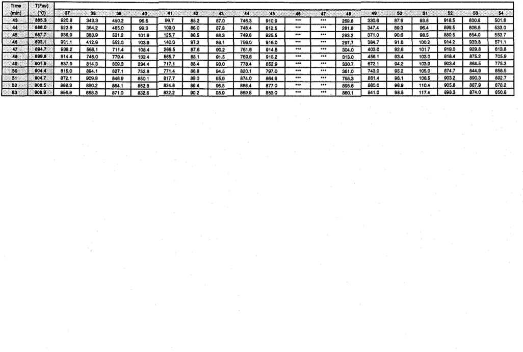
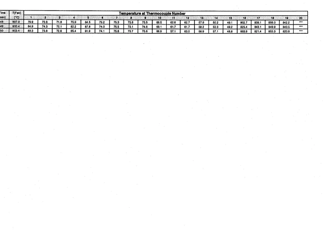
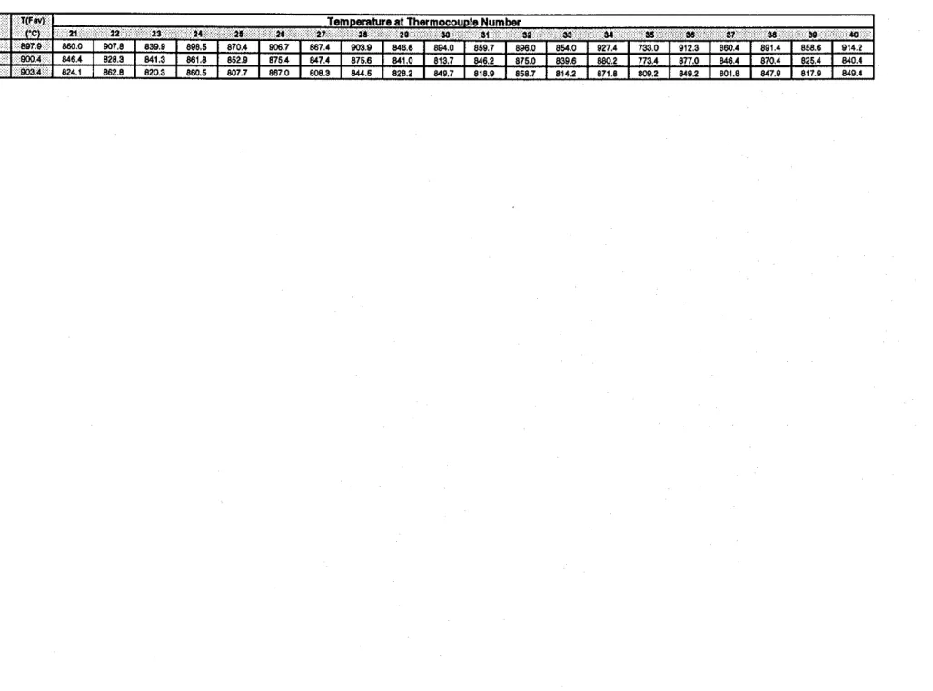
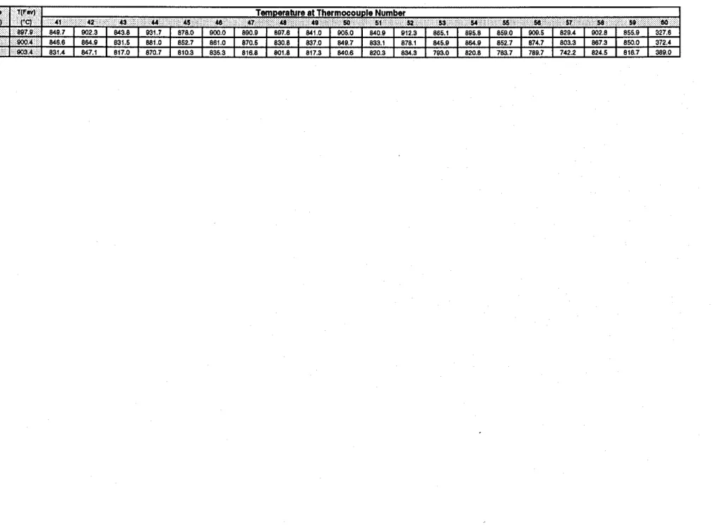
4.3 Recording of Results
The furnace and wall assembly temperatures were recorded at 1 minute intervals.
5.0 RESULTS AND DISCUSSION
The results of the 7 full-scale fire tests are summarized in Table 1 in which the single point and average failure times are given for each assembly.
Tabular data for each test are presented in the following:
The average temperatures measured on gypsum board surfaces and on the studs are plotted in Figures 28 to 34. Detailed temperatures for all nine thermocouples under the insulation pads on the unexposed sulface are also plotted in the Figures.
The deflections measured at the unexposed surface are plotted in Figures 35 and
36.
Test
5.1 Effects of Glass Fibre in the Gypsum Core of Loadbearing Regular Lightweight Gypsum Board Wall Assemblies
Average Surface Temperature Tables Single Location Temperature Tables
Two gypsum board assemblies amgements were studied: (1x1) one layer of gypsum board on each of the exposed and unexposed sides and (2x2) two layers of gypsum board on each of the exposed and unexposed sides.
Deflection Measurement
Tables
Single Gvpsum Board Laver (1x1) Assemblies (Figure 37)
Tests F-01 and F-OlB were carried out to investigate the effect of the presence of glass fibre in the gypsum core on the fire resistance rating of 1x1 gypsum board assemblies using a lightweight regular gypsum board (7.35 kg/m2). The structural failure and flame pcnetration criteria were reached at 33 min for Test F-01 (with glass fibre in the gypsum
core) and at 26 min for Test F-OlB (without glass fibre in the gypsum core). These results showed that, Assembly F-01 provided a 27% increase in fire resistance compare to
Assembly F-O1B. Therefore, the presence of glass fibre in regular lightweight gypsum board core did have an effect on the fire resistance performance of (1x1) regular gypsum board wall assemblies.
Double G v ~ s u m Laver (2x2) Assemblies (Fi~ure 38)
Tests F-02 and F-02B were conducted to investigate the effect of the presence of glass fibre in the gypsum board core on the fire resistance ratings of (2x2) gypsum board wall assemblies using a lightweight regular gypsum board (7.35 kgh?). The structural failure and flame penetration criteria were reached at 53 min for Test F-02 (with glass fibre in the gypsum core) and at 49 min for Test F-02B (without glass fibre in the gypsum core). These results showed that, Assembly F-02 provided a slight increase (8%) in fire resistance performance compared to Assembly F-02B. Therefore, the presence of glass fibre in regular lightweight gypsum board did not play a significant role in the fire resistance rating of double layer (2x2) assemblies.
5.2 Effects of Different Masses per Unit Area of Regular Gypsum Board Assemblies (Figure 39)
Test F-03 (lightweight regular gypsum board with glass fibre in the gypsum core, 7.35 kg/m2) and Test F-05 (heavy regular gypsum with no glass fibre in the gypsum core, 7.82 kg/m2) were conducted to investigate whether the reduction in the mass per unit area of gypsum board has an effect on the fire resistance ratings of 2x2 assemblies. The temperature failure criterion was reached at 63 min for Test F-03 and at 69 min for Test F-05. These results showed that, in double layer assemblies (2x2), using heavier gypsum board provided a 10% increase in fire resistance performance compared to using lightweight regular gypsum board.
5.3 Effects of Different Stud Types in Non-Loadbeariug Regular Lightweight Gypsum Board Wall Assemblies (Figure 40)
Test F-03 and Test F-04 were conducted to investigate the effect of stud type (wood and steel) on the fire resistance ratings of double layer (2x2) gypsum board wall assemblies using a lightweight regular (7.35 kg@) gypsum board with glass fibre in the gypsum wallboard core. The temperature failure criterion was reached at 63 rnin for Test F-03 (steel studs) and at 65 min for Test F-04 (wood studs). The difference in the fire resistance rating is considered within the error for the test procedure. These results showed that, in double layer lightweight regular gypsum board assemblies, non-
loadbearing, the type of stud was insignificant.
6.0 CONCLUSIONS
1. The presence of glass fibre in regular lightweight gypsum board affects the fire resistance performance of (1x1) lightweight regular gypsum board loaded wall assemblies but does not substantially affect the fire resistance rating of (2x2) lightweight regular gypsum board non-loaded wall assemblies.
2. In (2x2) regular gypsum board non-loaded wall assemblies, heavy weight gypsum board provided a better fire resistance rating than lightweight gypsum board. 3. In (2x2) regular gypsum board non-loaded wall assemblies, the type of stud was
7.0 REFERENCES
1. CANICSA-A82.27-M91, Gypsum Board-Building Materials and Products.Canadian Standards Association, Rexdale, Ontario, 1991
2. CANICGSB-7.1-M86, Cold Formed Steel Framing Components. Canadian General Standards Board, Ottawa, Ontario, 1986
3. CSA 0141-1970, Softwood Lumber, Canadian Standards Association, Rexdale, Ontario, 1970
4. CANICSA-A82.3 1-M91, Gypsum Board Application, Canadian Standards Association, Rexdale, Ontario, 1991
5. CANLJLC-S101-M89, Standard Methods of Fire Endurance Tests of Building Construction and Materials. Underwriters' Laboratories of Canada, Scarborough, Ontario, 1989
6. Lie, T.T. and Berndt, J.E., Remote Measurement of Large Deflections in Fire Tests, Division of Building Research, National Research Council Canada, Building Research Note No. 84, 1972.
7. Shorter, G. W. and Harmathy, T. Z., "Fire Research Furnaces at the National Research Council, Fire Study No.1. Division of Building Research, National Research Council Canada, NRC 5732, 1960
Table 1. Full-Scale Assembly Parameters and Fire Test Results
RH - Low denslty regular gypsum board. no glass flbre In gypsum core (7.80 kg/rn2) RL
-
Low density regular gypsum board, wlth glass flbre In the gypsum core (7.35 kg/m2) RL'-
Low denslty regular gypsum board no glass flbre In the gypsum core (7.27 kg/m2)Table 3. Average Temperatures Measured in Full Scale Assembly F-01, Wood Stud, 1x1 Gypsum Layers, No Insulation, Loaded Assembly
Legend: BL
-
Base Laver. FL-
Face Laver. Cav.-
Cavity. SStd.-
Steel Stud, WStd.-
Wood Stud, Av-
Average. Exp.-
Exposed Side, UnExp.-
Unexposed Sidelln l(Fav) B L ~ S I O . ( E X ~ . ) BUav. (ESP.) HIO WSIL BLIWSta. (UnErp ) nucar. (UnElp.) UnExe (""1 CC) A"i24.15.26.56.17. Av~m21,40,4!~2LZbO Ar(3O.31,323.U,SI. A"in,28,29.38.39, AvinP.4aU.I5.M,~~ ~v(1.~,3.4,5.8.r.s.e)
48,47,W,SI,S2) W.S7.P.S9.60.61) 48.49.SY.w.55)
Table
5.
Average Temperatures Measuredin
Full Scale Assembly F-OIB, Wood Stud, 1x1 Gypsum Layers, No Insulation, Loaded AssemblyLeaend: BL
-
Base Lavu. FL-
Face Layer, Cav.-
Cavltv. SStd. -Sled Stud. WStd. -Wood Stud. Av-
Average. Em.. Exposed Slde. UnExp.-
Unexposed Slde~ l m T ( F ~ J h w s t d IExp.1 euuv. ( ~ x p ) H a WSM s r m s t a . p ~ n ~ x p . 1 BUUV. IUnExpJ Unmp.
I M ~ I VCI Av(24.15 14 Av(36,37.38. A~(lV,l7,ILlO, Av(30,31.31.93,34.35) r v ( s . u . u . ~ s . l s . o ] A~IL,~.4,SA.7.8.O1 27.1L1BJ 30.40.41) 2011 11 13)
Table
7.
Average Temperatures Measured in Full Scale Assembly F-02, Wood Stud, 2x2 Gypsum Layers, No Insulation, Loaded AssemblyLegend: BL - Base Laver. FL
-
Face Laver. Cav.-
Cavltv. SStd.-
Steel Stud. WSld.-
Wood Stud. Av - Averape, Exp.-
Exposed Stde. UnExp.-
Unexposed SldeTlnv 1 ( f n ) B W L i k V l IIVWSId IEXD) E&r. (Exp) Mld. W a d lIVCa. (UnEip.) EWsld.(unExp.) B W L (UnETpj UnElp.
(mlnl ('C) A~l18,17,24,2S,M,37,44, AV(l8.27,P. ~v(18,10.46, Avi28,2@,m,31, AV120.21.48. Av(3L3%*0. AvlU23,d4.W,42) AY11.2.3A.S. 4~5.sz,rc.sr,ss~ ~O.M.SSJ 47, e8.a) ,SL~~.WPO) ~B.ML@I 11,m,e1)
Table 7. Average Temperatures Measured
in
Full Scale Assembly F-02, Wood Stud, 2x2 Gypsum Layers, No Insulation, Loaded Assembly (Cont.)Table 8. Temperatures Measured
in
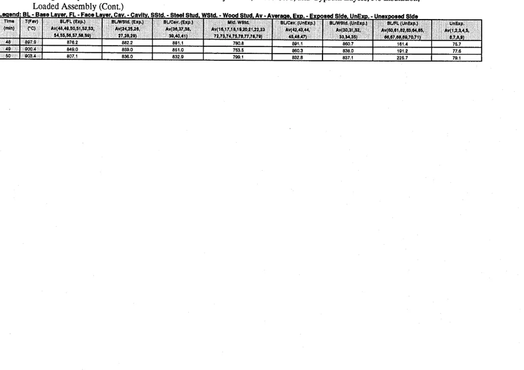
Full Scale Assembly F-02B, Wood Stud, 2x2 Gypsum Layers, No Insulation, Loaded Assembly (Cont.)Table 9. Average Temperatures Measured
in
Full Scale Assembly F-02B, Wood Stud, 2x2 Gypsum Layers, No Insulation, Loaded AssemblvLeqend: EL. Base Laver, FL
-
Faca Layer. Cav.-
Cavltv. SStd. -Steel Shld. WSU.-
Wood Stud, Av-
Averaae, EXD.-
Exoosed Side. UnExo. -Unexposed SideTim* T ( F ~ # ) BJFLIUP I ~ U W s l d . I ~ r p . j aL/Car. (Cap) Mid. WBU. B U O V IUntYP.) EUWSld.(UnEYp.l OWL (UnEap.) UnExp. ( ~ n l ~ C I ~ v ( 4 8 * o . ~ . 5 t . ~ ~ . ~ , bV(l4.lS26, Av(36.37.W *v(16,17.16.192021.2223 AV(42,4¶,4+ Av(JO.31 B1, ~ ~ ( ~ , 6 1 , a , t q 6 * , % , A ~ ( 1 5 2 . * L ~
s ~ . s % 5 ~ , ~ 7 , a , s o j n.ae.lq ~o.ra.41) 72.75 74.75.78.77.71.79) u,rs 41) 3 3 . ~ ~ ~ 4 m,87,~,69,70,71) b.7.8,O)
. . . . .-
-
.- - - A A .. . ~ ~~ ~ a , : . : : : :.8@7,6::<
Table 9. Average Temperatures Measured
in
Full Scale Assembly F-02B, Wood Stud, 2x2 Gypsum Layers, No Insulation, Loaded Assembly (Cont.)Table 9. Average Temperatures Measured in Full Scale Assembly F-02B, Wood Stud, 2x2 Gypsum Layers, No Insulation,
Table 13. Average Temperatures Measured in Full Scale Assembly
F-04,
Wood Stud, 2x2 Gypsum Layers, No Insulation, Loaded Assembly Lwend: BL-
Base Laver. FL-
Face Laver. CaV. -Cavity. SSld.-
Sted Stud. WSM.-
Wood Stud. Av -Avuaae. EXD.-
Exwsed Slde. UnExp.-
Unexrrosed Sldenm 1mb1
I
BLFL ( e p . ) Av(I8,l7,18,28,20, ~ , a l . 4 4 . ~ . , ~ 1 ) ~ ( m ) co BLmS1d (Exp) Av(a0,¶1,~.39) IIUCIY. (-9.1 Av(1010.11, 47.48 lo) aUC.r.(un~p.) Av(12,23,24, W,SI.SI) ~ ~ 8 l d . ( u n e r ; p . ) AV(~2,SAO. 4l.80.81) BUFL(LIIUIp.) A V I ~ S . ~ , Z ~ . ~ * . S S 42,43,S3,54,55) UnUp. Av((,2,44,S. 8,ld.O)Table 13. Average Temperatures Measured in Full Scale Assembly F-04, Wood Stud, 2x2 Gypsum Layers, No Insulation, Loaded Assembly
Leaend: BL
-
Base Laver. FL -Face Laver, Cav.-
Cavltv, SStd.-
Steel Shld. WSM. -Wood Stud. Av-
Averaae. Exp. -Exposed Slde, UnExc...
Unexposed Sldellma 1mln1 T(Fw) ('c) 86.57.44.45.44) EL~FL l a p . ) AV(lO,l?,l428,2#, 41,44,10) 8VW81d (EXp.1 ~ ~ ( ~ 3 1 3 8 . 9 9 ) (IVCN. (E.p.) Av(lOLO.21,
WJI.52) 4IbO.61) 42C3,53.M.UI 67.8.q
BUC.v.(UnUp.) Avl22,Z3,24, B W l d . lUnE~p.l AvI3I.B)CO. ELIFL (UIRp.) Av(2S.~.ZI.B4,86, UnElp. AV(l32,%4,S,
Table 15. Average Temperatures Measured in Full Scale Assembly F-05, Steel Stud, 2x2 Gypsum Layers, No Insulation
Lwend: EL
-
Base Layer. FL-
Face Laver, Cav.-
Cavltv. SStd.-
S t d Shld. WSU.-
Wood Stud. Av-
Avuwe. Exa-
E x m a d Slde. UnExD.-
Unexwsed SldeTlrm 1IF.v) 8 W L ( P p ) E U S S l d (Elp.) BLEW. (ExP.) Mld. 881d BVCav. (UnExp.) swsla (UnExp) B W L ( U n U p . ) u n ~ r p . lmlnl I'C) Av(76,17,24,26, AV.V(~O,I~..W a7) AV(7419.46.47) AYIL2D.M.JD) AV12011 48.491 Av(3081.(0, Ar(l?,?bW;(a, A~ll,*,%4.h
Table 16. Centre Deflections Measured in Full-Scale Assembly F-01, Loaded Assembly
Table 17. Deflection Measurements in Full Scale Test F-OlB, Loaded Assembly
Table 19. Deflection Measurements in Full Scale Test F-02B, Loaded Assembly
hird Stud From Left Un ed Face. Centre Deflection
Table 20. Centre Deflections Measured in Full-Scale Assembly F-03, Unloaded Assembly
Table 21. Centre Deflections Measured in Full-Scale Assembly F-04, Unloaded Assembly
/-- Fixed Flue Fixed Rue 7
(a) Section (b) Front Elevation With Test Assembly Removed
Fire Exposed Side . . 4 0 50 20
1::
36 41 48 51 82 21 26 37 42 47 52 63 89.0 rnrn-
L A
Unexposed Sidet=-
8 Studs @ 400.0 rnrn O.C.P
I
I-J
k 4 0 0 . 0 rnrn 1 3 6 5 7 . 6 rnrnd
Dmring Not To Scale
Figure 2. Thermocouple Locations in Full-Scale Test
F-01
Section A-A
Fire Exposed Side
Unexposed Side
I--
8 Studs @ 400.0 mm O.C.1
Section A-AI
E
E
9 N cO r. 34"7
3a n1
E E 9 N In r.7
/ 3 5 5 1 . 6 rnrnd
Drawing Not To S a l eFire Exposed Side
Unexposed Side
Dmsing Not To Scoia
Figure
4.Thermocouple Locations in Full-Scale Test F-03
5 Studs @ 600.0 rnrn O.C. 18 24 34 42 28 36 U !iz 18 22 30 38 4E 54 2 0 5 2 4 0 5 0 56 2 8 . . • 4E 8 -?
Section A-A E E 9 m P; 0 r] 17 25 35 41 19 27 37 43 21 31 30 452?
2 9 . 7 ?' ,7 ,:O 53 55 57:D
-3657.6 rnmFire Exposed Side
Unexposed Side
Section A-A
Dmrrlnq Not To Ssol.
t-
5 Studs 63 600.0 rnrn O.C.Figure 5. Thermocouple Locations in Full-Scale Test F-04
r
E E 9 m d 0 r)L
jj.
25 17 20. 2s '26 m JO 37. 34 n 1 35 18 21 ' 24 27i
!
g
B
5? $ 0 w Qlb.Fire Exposed Side
1
90.0 rnrn7
Unexposed Side SectionDmxing Not To Scale
P
5 Studs @ 600.0 rnrn O.C.1
A-AI
r'
E E 9 m*
0 r?L.;
Figure 6. Thermocouple Locations in Full-Scale Test F-05 ' ,
m ;
34 36 40 sa!? 35 37 41*?
I I8 18:a
.
28. 17 IS 21 2 : 29 ; i 24g
32.
$ 31?
; '
,
44 46 48 Js I 50 45 47 49 5!Fire Exposed Side
Unexposed Side
r-
8 Studs @ 400.0 rnrnI
Section A-A1
4
/L
400.0 rnrnI
I
a
3657.6A
rnrn-
-Drawing Not To Smla
Fire Exposed Side - A 52 54 56 59
6
89.0 rnrn 7 Unexposed Sideb
-
8 Studs @ 400.0 rnrn-q
k
400.0 rnrn 1 1 3 6 5 7 . 6 rnrn4
Drawing Not To Scole
Section A-A
Fire Exposed Side
1
89.0 mrn7
Unexposed Side Joint-
3657.6 rnrn1
Drowinp Not To Sfoh
Figure 9. Screw Locations For Wood Stud, 1x1 Gypsum Board Layers, Full-Scale Assembly, Base Layer Gypsum Board,
Fire Exposed Side
d
89.0 rnrnP
Unexposed SideI
-
3651.6 rnrn-1
Dmwing Not To Yale
Figure 10. Screw Locations For Wood Stud, 1x1 Gypsum Board Layers, Full-Scale Assembly, Base Layer Gypsum Board,
Fire Exposed Side
2
89.0 rnrn Unexposed Side Dmring Not To Smls 8 Studs @ 400.0 mm O.C.. .
.
.
1
Figure 11. Screw Locations For Wood Stud, 2x2 Gypsum Board Layers, Full-Scale Assembly, Base Layer Gypsum Board,
Fire Exposed Face
.
E E 9 m d. 0 r)I
1
"I
I
"1
1
$
I I I I I If!
0I
I
I
I
I
I
V) I I I I I I -tI
2
I I I I I II
II
II
II
I 50 mmI
II
I. .
-PI-- J1
3657.6 mmj
-
.
"
I II
II
II
I
I II
I
I II
I
.
1 1I
I
I II
I
I I I I I II
II
II
II
I..
I
I
..
I
I I I/
II
I
I
I
7
I I I 0I
I
kI
1
10 mm E I 10 mm.
1 1.
.
1I
I
I
-&
I II
I
I II
I II
I
I I 9 0 0 w 8Fire Exposed Side
Unexposed Side
Joint
Figure 12. Screw Locations For Wood Stud, 2x2 Gypsum Board Layers, Full-Scale Assembly, Face Layer Gypsum Board,
Fire Exposed Side
Unexposed Side
Board Joint
Drawing Not To %do
I--
8 Studs @ 400.0 mm O.C.Gypsum
. .
.
.
. .
I I I I II
II
I I II
..
1 1I
1I
..
1I
1I
. .
2
I
I
I
I
I
G
I I I I 0 I 10 mm. .
. .
I
. .
E E 1 1 I I 1 EFigure 13. Screw Locations For Wood Stud, 2x2 Gypsum Board Layers, Full-Scale Assembly, Base Layer Gypsum Board,
Unexposed Face E 4
3
0 *)I
I
I
I
I
$
I I I I I E' uI
I
I
I
I
V) I I I I I d--
1
"1
I
"1
1
..
I I I I IP
I
I
1
50 rnm I. .
I I-
. .
I
II
I. .
I
II
1.
I
I
I II
I
.
1 1.
I
I
I II
I
.
1 1.
.
9 0 0 w 8Fire Exposed Side
Y 89.0 rnm
Unexposed Side
Dmwinp Not To Sc&
8 Studs @ 400.0 m m O.C. Gypsum 8
. .
.
.
I I I I I I I I I I I I I "1
II
I "1
1
1 1 0I
I
EE
I I 10 rnm I I I I E E "1
1
"I
1
k 9 0Figure 14. Screw Locations For Wood Stud, 2x2 Gypsum Board Layers, Full-Scale Assembly, Face Layer Gypsum Board,
Unexposed Face 9 m
*
0 rr) loard JointI
I
I
I
I
I
e
I I I I I Ie
0t
I
"1
1
"
t
t
In I I I I w 1 1. .
I
1 1I
. .
1 1I
II
I.
.
I
II
I. .
I
II
I I II
1I
1.
I I.
I
1 1I
.
I I 10.
I
1I
14 -
0 rnm + 0Fire Exposed Side
d
89.0 rnrn-7-
Unexposed Side-
Board Joinhawing Not To Scab
1 5 Studs 8 600.0 rnrn O.C. bypsurn
Figure 15. Screw Locations For Wood Stud (600 mm
O.C.),
2x2 GypsumBoard Layers, Full-Scale Assembly, Base Layer Gypsum Board, Fire Exposed Face
E E 9 a d- o l'l
1
1657.6 rnrn-1
rset
.
II
.
I1
.
II
.
II
t.
I
I.
I
I1
I!.
II
II
II
I. . .
. .
.
.
. .
.
. .
I I.
I
.
.
I
I I.
1
. .
I
I -k 10 rnrn 1: L q
* I.
.
II
.
.
II
.
I
I.
-
I
-
-I
I.
I
II
.
II
.
I.
. . .
I.
I
.
1I
.
I
II
.
IG
0 E E8
rr) 8 V )f
3 I:
.
V)I
0 ) I.
I
I.
I
50 rnrn I Ce.
.
.
1
Fire Exposed Side
89.0 rnrn
-
Unexposed Side
Figure 16. Screw Locations For Wood Stud (600 mm O.C.), 2x2 Gypsum Board Layers, Full-Scale Assembly, Face Layer Gypsum Board, Fire Exposed Face
Fire Exposed Side
Unexposed Side
Figure 17. Screw Locations For Wood Stud (600 mm
O.C.),
2x2 Gypsum Board Layers, Full-Scale Assembly, Base Layer Gypsum Board, Unexposed FaceFire Exposed Side 'I 89.0 rnrn
-
Unexposed Side-
- 1 BoardDrawing Not To Sole
5 Studs 8 600.0 rnrn O.C. bypsun
Joint
Figure 18. Screw Locations For Wood Stud (600 rnm O.C.), 2x2 Gypsum Board Layers, Full-Scale Assembly, Face Layer Gypsum Board, Unexposed Face
.
. .
.
.
I If
. .
t
.
I I1
. .
1
.
II
. .
II
I I.
I
L:.,
,
-
,
:
f
I
I
m 5f!
I I I 0t
t
. .
I
V) m I I II
I
.
.
I II
IJ
J
.
.
J
I I 50 rnrn I.
. .
.
.
. .
I=-.
. .
11
. .
.
.
.
I.
I.
4
10 rnrn I & - -k.
I
I
.
I
tI
.
LI
.
I 1.
'7
' 1 0 mm 0 E E 0 n 0 8.
I
t.
E
EI
I
9 1. .
1.
u)*
0I
I
I I.
Fire Exposed Side
Unexposed Side
Joint
-
m7.r
rnrn2
Drawing Not To Ssok
Figure 19. Screw Locations For Wood Stud (600 mm O.C.), 2x2 Gypsum Board Layers, Full-Scale Assembly, Base Layer Gypsum Board, Unexposed Face
Fire Exposed Side
Unexposed Side
Gypsum Board Joint 5 Studs @ 600.0 mm O.C.
3657.6 mrn
1
-Dmwing Not To Ssds
Figure
20.
Screw Locations For Wood Stud(600
mm O.C.),2x2
Gypsum Board Layers, Full-Scale Assembly, Face Layer Gypsum Board, Unexposed FaceFire Exposed Side
Unexposed Side
Joint
L
3657.6 rnm-1
Drawing Not To k o b
Figure 21. Screw Locations For Steel Stud, 2x2 Gypsum Board Layers, Full-Scale Assembly, Base Layer Gypsum Board,
Fire Exposed Side
Unexposed Side
,Gypsum Board Joint
[-
5 Studs @ 600.0 m m O.C.Figure 22. Screw Locations For Steel Stud, 2x2 Gypsum Board Layers, Full-Scale Assembly, Face Layer Gypsum Board,
E E 9
7
E 036
11.
&i 18.
6
E*
0 r)7 "
4. .
3 14 16 1219.2 rnm 3251.2 mm Dmwhg Not To SmloEl Thermocouple Under Std. ULC S101 Insulated Pad Bare Thermocouple
Figure 23. Thermocouople Locations on Unexposed Surface Full-Scale Tests
Fire Exposed Side
Unexposed Side
/--
Gypsum Board JointOmwing Not To Scole
@ Attatchment Point For Measurement of Deflection During Test
Fire Exposed Side
1
90.0 rnm
7
Unexposed Side
Stud 2 Stud 4 Stud 6
Dmwinq Not To Scale
@ Attatchrnent Point For Measurement of Deflection During Test
I I I I I
I
II
II
II
II
II
II
I II
I
II
II
II
II
II
II
IE
I
II
II
I
II
IE
9I
II
Ii
I
II
I 00 -t 0I
II
II
II
I II
II
II
II
I7
I
II
I
I
I
I
I I I I II
I
I
I
I
I I I I IFigure 25. Deflection Attatchment Points For Full-Scale Tests (F-03, F-05) E
E
2
N In-
I
II
II
II
IC
5 Studs O 600.0 mrn O O.C. 3657.6 mrn3
Fire Exposed Side
Unexposed Side
/-
Gypsum Board Joint
Stud 3 Stud 6 Stud 8
8 Studs @ 400.0 mm @ O.C.
I
-
3657.6 mmDmwing Not To Soal.
@ Attatchment Point For Measurement of Deflection During Test
Fire Exposed Side
Unexposed Side
Stud 3 Stud 6 Stud 8
Joint
Dmxing Not l o Scole
@ Attatchment Point For Measurement of Deflection During Test
(a) Average Face Temperature Distribution Average Values
800 - ULC Furnace Temp.
9
-
g
600 3.-
BLIWStd. (UnExp.)s
BUCav. (UnExp.) a, 400e
2
200 Failure Criterion 1 (Rm. Temp. + 139'C) 0 0 10 20 30 40 50 Time (min.)(b) Unexposed Temperature Distribution - Thermocouple 1 - - - .
. - - Thermocouple 2 Thermocouple 6 ... Thermocouple 3 Thermocouple 7 ... Thermocouple 4 - Thermocouple 8
-
-Thermocouple 9 Failure Criterion 2 (Rm. Temp. + 180'C) 10 2030
40 50 Time (min.)1000 I I I
(a) Average Face Temperature Distribution , _ / I
Average Values
800 -
-
- ULC Furnace Temp. -p
- - - BuWStd (Exp.) .---.-
BUCav. (Exp.) 600-
Mid WStd.-
3 C ... . . . . 8UWStd. (UnExp.)-
s
a, BUCav. (UnExp.) 400 - UnExp.-
r-"
200-
* ,, ,.y Failure Criterion 1
-
--=-
-.---
,.;.* ..=-=-- ~dew-. ~~.~~~~~iiiiiiiii----
-
-
- ---;; .d-^..c; 5- (Rm. Temp. + 139'C)-
-...-..: -.., ~-.-=:~ 0 I I I 0 10 20 30 40 Time (min.) 100 50 0 0 10 20 Time (min.)(b) Unexposed Temperature Distribution - Thermocouple 1 ---..-.- Thermocouple 5
- - -Thermocouple 2 Thermocouple 6 .---- Thermocouple 3 Thermocouple 7 Thermocouple 4 -
-
-Thermocouple 9 Failure Criterion 2 (Rm. Temp. + 160'C)1 1 ' 1 1 " ' 1 1 1 ' 1 1 " 1 " ' 1 1 1 ' 1 1 1 '
Average Values
- ULC Furnace Temp. -
-
. - - BUFL (Exp.) .---- B W S t d . (Exp.) BUCav. (Exp.)
-
. .. . . Mid. WStd. BUCav. (UnExp.) --
B W S t d . (UnExp.)-
-
BUFL (UnExp.)- -
UnExp. Failure Criterion 1-
(Rm. Temp. + 139'C)-
1 1 1 , 1 1 1 1 Time (min.) 5 0 0 ~ ~ I r a ~ ~ ~ ~ m ~ o ~ ~ ~ s m n ~ s ~ m ~ c ~ ~ ~ ~ ~ ~ ~ Unexposed Face450 (b) Unexposed Temperature Distribution - Thermocouple 1 ... .. Thermocouple 5
-
:400
F
- - - Thermocouple 2 Thermocouple 6 7 --- Thermocouple 3 --- Thermocouple 7-
Thermocouple 4-
Thermocouple 8 :-
-Thermocouple 9 250-
5
2
200 : (Am. Temp. Failure Criterion 2 + 180'C) 1 I150
-
100 -
Time (min.)
l l l ' l ' l ' l " r l z " l l r 1 1 , 8 8 1
Average Values
- ULC Furnace Temp.
-
-- - - BUFL (Exp.) .---- BUWStd. (Exp.) BUCav. (Exp.)
-
. . . Mid. WStd. BUCav. (UnExp.)-
BUWStd. (UnExp.) --
-
BUFL (UnExp.)- -
UnExp. Failure Criterion 1-
(Rm. Temp. + 139'C)-
1 , , 1 , , 1 1 , , , 10 20 30 40 50 60 70 80 Time (min.) 10 20 30 40 50 60 70 80 Time (min.) Unexposed Face(b) Unexposed Temperature Distribution -Thermocouple 1 ---..
- - - Thermocouple 2 Thermocouple 6 .-... Thermocouple 3 --- Thermocouple 7 --Thermocouple 4
-
-
-Thermocouple 9 Failure Criterion 2 (Rm. Temp. + 180'C)1000 r r . , r . m , m 8 8 1 8 8 r 1 8 ~ C , , , , , , , , , , , , , , , ,
.--
(a) Average Face Temperature Distribution Average Values
ULC Furnace Temp.
-
-- - - BUFL (Exp.) --- BUSStd. (Exp.) BUCav. (Exp.)
-
Mid. SStd. BUCav. (UnExp.)-
BUSStd. (UnExp.)-
-
-
BL1FL (UnExp.)- -
UnExp. Failure Criterion 1-
(Rm. Temp. + 139'C)-
, , ( , I , , ( 0 10 20 30 40 50 60 70 80 90 Time (min.) Thermocouple 1 ...--- Thermocouple 5 - - -Thermocouple 2 Thermocouple 6 ..--- Thermocouple 3 --- Thermocouple 7 Thermocouple 4-
-
-Thermocouple 9 Failure Criterion 2 (Rm. Temp. + 160'C)0
10 20 30 40 50 60 70 80 90 Time (min.)0
0 10 20 30 40 50 60 70 80 90
Time (min.)
l l l r l ~ ' l l l ' l l ' ' ' l s l s l l s 1l 9l 1 1 1 8 8
Average Values
ULC Furnace Temp.
-
-
- BVCav. (UnExp.) - BWStd. (UnExp.)
-
-
Failure Criterion 1-
(Rm. Temp. + 139'C)-
40 50 60 70 80 90 Time (min.)(b) Unexposed Temperature Distribution - Thermocouple 1 ... Thermocouple 5
- - - Thermocouple 2 Thermocouple 6 ... Thermocouple 3 --- Thermocouple 7 Thermocouple 4 -Thermocouple 8
-
-Thermocouple 9 Failure Criterion 2 (Rm. Temp. + 180'C)0
0 10 20
30
40 50 60 70 80 90 100Time (min.)
i " l l ' L 1 l l l l l ' l ' l " ' l " o l " ' l ' l ' l " '
-
(a) Average Face Temperature Distribution ,. Average Values -- ULC Furnace Temp. -
- - - BUFL (Exp.)
-
.-... BUSSld. (Exp.) BUCav. (Exp.) . . .. . ... . Mid. SStd.-
BUCav. (UnExp.)-
..-.- BUSStd. (UnExp.)-
-
BUFL (UnExp.)-
- -
UnExp. Failure Criterion 1-
(Rm. Temp. + 139'C)-
~ , , , 1 , , , 1 , , , Unexposed Face Thermocouple 1 .---Thermocouple 5 - - - Thermocouple 2 Thermocouple 6 --- Thermocouple 3 --- Thermocouple 7 Thermocouple 4-
-
-Thermocouple 9 Failure Criterion 2 (Rm. Temp.+
180'C) Time (min.)(a) Deflection Measurements For Loaded Full-Scale Assemblies F-01, F-02 5 l " ' l Z a 8 l 3 , I 8 s z l - 4 8 L 0 - - - _ - _ _ - _
- - _ _
A- -
E.
.
0 -5:
.
.
-
\ C,
0 \.-
-
-10-
\ 0 w I=
I:
-15r
- Assembly F-01, Mid Stud Deflection, Stud 6 I- - - . Assembly F-02, Mid Stud Deflection, Stud 6 I I
-20
-
ITime (min.)
(b) Deflection Measurements For Unloaded Full-Scale Assemblies F-03. F-04. F-05
Time (min.) A E 0 0
-
K 0.-
-
0 w e w -5n
. ~ n L _____...---.____..-
.-
---.-=..---.--== -;-;;--
-
-
- Assembly F-03, Mid Stud Deflection, Stud 4
-
Assembly F-04, Mid Stud Deflection, Stud 6-
. - - - Assembly F-05, Mid Stud Deflection, Stud 4I I I
Time (min.)
(c) Deflection Measurements For Loaded Full-Scale Assembly F-01 B
5 C . 8 . , 8 r ~ , . . , , . , , , , , . , , . ,
-0 -
-
5
-5-
Figure
35.Measured Deflections For Full-Scale Assemblies
-
C 0=
-10: 0 m e$
-15 -20-
- Mid Stud Deflection, Stud 3
7 . - - Mid Stud Deflection, Stud 6
-
-
.---.. Mid Stud Deflection, Stud 8Time (min.)
Deflection Measurements For Loaded Full-Scale Assembly F-02B
5 l " ' l " ' l ' l l l " ' l " ' _ 0
-
6
-5-
c o.-
-
-10: 0 a,-
-
a, -15 D -20 -25 Time (min.)-
- - - --
:
-
- Centre Deflection, Stud 3 -
- - - 314 Stud Height, Stud 3
-
:
-
I , , * l , s , 1 , 8 , 1 , , , 1 , , # - ,
Deflection Measurements For loaded Full-Scale Assembly F-028
Deflection Measurements For Loaded Full-Scale Assembly F-02B
5 1 " 1 1 " ' 1 1 " 1 8 8 1 1 1 1 0 10 20 30 40 50 60 0
-
6
-5-
C 0.-
-
-10 0 a,=
-15E
-20 -25 0 - -5-
- Centre Deflection, Stud 8
-10 - . - - . 314 Stud Height, Stud 8 -15
-
-20
-
:
5 - 8 . 8 , , 8 , , # , . , , , , , , . , , , . ,
-
---
-
r
-
- - Centre Deflection, Stud 6
-
. - - 314 Stud Height, Stud 6
-
-
-
-
1 1 1 l l l l . l l l l l , , , l , , ,
-Time (min.)
0 10 20 30 40 50 60 -
(Ixl,12.7 mm, Type RL Gypsum Board)
RL
-
Regular Lightweight Gypym Board with Glass Fibre in Gypsum Core (7.35 kglm )R<
-
Regular Lightweight Gypym Board with no Glass Fibre in Gypsum Core (7.27 kglm )Figure 37. Effect of Glass Fibre in Lightweight Regular Gypsum Core on the Fire Resistance Ratings of Loadbearing
(2x2,12.7 mm, Type RL Gypsum Board)
53 min 49 min
RL
-
Regular Lightweight Gypsum Boa$ with Glass Fibre in Gypsum Core (7.35 kg/m )RC
- Regular Lightweight Gypsum Boqd with no Glass Fibre in Gypsum Core (7.27 kglm )Figure 38. Effect of Glass Fibre in Lightweight Regular Gypsum Core on the Fire Resistance Rating of (2x2) Assemblies
(2x2,12.7 mm, Type RL and RH Gypsum Board)
63
min69
minRL
-
Regular Lightweight Gypym Board with Glass Fibre in Gypsum Core (7.35 kglm )RH - Regular Gypsu~Board with no Glass Fibre in Gypsum Core (7.80 kglm )
Figure
39.
Effects of Different Mass Per Unit Area of (2x2) Regular(2x2,12.7 mm, Type RLGypsum Board)
63 min 65 min
RL - Regular Lightweight Gypsum Board (7.35 kg/m2)
Figure 40. Effect of Stud Types (Wood and Steel) on the Fire
Resistance Rating of Non-Load bearing (2x2)