Publisher’s version / Version de l'éditeur:
Canadian Geotechnical Journal, 31, August 4, pp. 491-501, 1994-08
READ THESE TERMS AND CONDITIONS CAREFULLY BEFORE USING THIS WEBSITE. https://nrc-publications.canada.ca/eng/copyright
Vous avez des questions? Nous pouvons vous aider. Pour communiquer directement avec un auteur, consultez la première page de la revue dans laquelle son article a été publié afin de trouver ses coordonnées. Si vous n’arrivez pas à les repérer, communiquez avec nous à PublicationsArchive-ArchivesPublications@nrc-cnrc.gc.ca.
Questions? Contact the NRC Publications Archive team at
PublicationsArchive-ArchivesPublications@nrc-cnrc.gc.ca. If you wish to email the authors directly, please see the first page of the publication for their contact information.
NRC Publications Archive
Archives des publications du CNRC
This publication could be one of several versions: author’s original, accepted manuscript or the publisher’s version. / La version de cette publication peut être l’une des suivantes : la version prépublication de l’auteur, la version acceptée du manuscrit ou la version de l’éditeur.
Access and use of this website and the material on it are subject to the Terms and Conditions set forth at
Frost protection of buried PVC water mains in western Canada
Sepehr, K.; Goodrich, L. E.
https://publications-cnrc.canada.ca/fra/droits
L’accès à ce site Web et l’utilisation de son contenu sont assujettis aux conditions présentées dans le site LISEZ CES CONDITIONS ATTENTIVEMENT AVANT D’UTILISER CE SITE WEB.
NRC Publications Record / Notice d'Archives des publications de CNRC:
https://nrc-publications.canada.ca/eng/view/object/?id=08c47f2a-c08d-4893-bb21-6a4468feec70 https://publications-cnrc.canada.ca/fra/voir/objet/?id=08c47f2a-c08d-4893-bb21-6a4468feec70SER
THI N21dI J ~ C C .-
S G ~ C /
Ci
National Research Conseil national
/i':cr
P-
32';
L1
+
1
Counc~l Canada de recherches CanadaC , 2
BLDG
no,
3 2 9 6 1 9 9 4Reprinted from
Canadian
Geotechnical
Journal
Reimpression de
la
Revue
canadienne
de
geotechnique
Frost protection of buried PVC
water mains in western Canada
K. SEPEHR
AND
L.E.
GOODRICH
Volume 31
Number 4
1994
Pages 491 - 501
CISTI/ICIST NRC/CNRC
IRC Ser
Received on:
1 1 - 2 2 - 9 4IRC paper
IRC paper
--
Bev Creighton
Frost protection of buried PVC water mains in western Canada
K. SEPEHR AND L.E. GOODRICH
Infrastructure Laboratory, Institute for Research in Construction, National Research Council of Canada, Ottawa, ON K I A OR6, Canada
Received March 26, 1993 Accepted March 7, 1994
Although desirable for many reasons, controlled low-strength material - controlled density fill (nonshrinkable fill) has the potential to promote rapid frost penetration within the trench when used as a backfill material in water- works construction and repair projects. This paper describes results of a two-dimensional finite-element heat-
7 transfer model study carried out to investigate the effectiveness of various insulation systems for frost and frost-heave
protection of buried waterlines. Combinations of nonshrinkable fill with horizontal insulation boards, cylindrical pipe insulation, and inverted U-shaped insulations were investigated. It was shown that, while moderate thicknesses of insulation could be found to protect the pipe from freezing, thermal-bridging effects make the location of the max- imum frost penetration depth sensitive to details of the insulation geometry. The use of different combinations of insu- lating backfills was also investigated, and it was shown that a backfill layer of moderate insulating value placed high in the trench may be most advantageous.
Key words: frost, frost protection, insulation, waterlines, nonshrinkable fill, numerical analysis.
Bien qu'Ctant souhaitable h beaucoup d'Cgards, un matCriau de remblai CLSM-CDF sans retrait peut favoriser la pCnCtration du gel dans les tranchCes oh il est utilisC lors de travaux hydrauliques et de projets de rkparation. Cet article dCcrit les rCsultats d'une Ctude par un logiciel de transfert de chaleur (ClCments finis h deux dimensions) faite pour Cvaluer I'efficacitC de diffkrents systbmes d'isolation visant h protCger des conduites d'eau enterrkes du gel et du soulbve- ment dQ au gel. Des combinaisons de remblai sans retrait avec des panneaux d'isolant horizontaux, des isolants tubulaires autour des conduites et des isolants en U-renversC ont CtC examinCes. On a montrC que l'on peut emp&cher les conduites de geler avec des Cpaisseurs modCrCes d'isolant, et que la profondeur maximale de pCnCtration du gel est trbs sensible aux dCtails gComCtriques de I'isolation B cause des effets de pont thermique. L'utilisation de diverses combinaisons de remblais isolants a CtC aussi examinCe et on a montrC que le plus avantageux Ctait d'utiliser une couche de remblai de valeur isolante modCrCe, placCe assez haut dans la tranchCe.
Mots cle's : gel, protection contre le gel, isolation, conduite d'eau, remblai sans retrait, analyse numCrique. [Traduit par la rkdaction] Can. Geotech. J. 31, 491-501 (1994)
1. Introduction warmer climates. During recent years the use of non-
In regions of intense seasonal frost, such as Western Canada, damage to buried services, such as pipe freezing, or differential frost heave and pavement settlement problems
shrinkable fill in waterworks construction and repair projects has begun to spread to Western Canada. It is attractive on the grounds that it satisfies most of the criteria mentioned pre- have long been recognized by engineers (crawford 1955;
Chan et al. 1981; Sasaki 1985). To protect buried utilities from frost, it is generally considered appropriate to require designs to be such that the frost front does not penetrate below the top surface of the utility. To achieve this level of frost protection in these regions, it is often necessary to bury water-distribution pipes to depths well below 2 m. This increases excavation and reinstatement costs substan- '
tially. The most economical and beneficial approach is to reduce the burial depth to the minimum necessary to pro- vide both frost and structural protection for the pipe.
For new construction as well as for utility trench rein- statement, it is desirable to use a backfill material that com- bines low material costs, small labour effort for handling and placing, and little or no tendency for subsequent set- tlement of the filled trench. The material must be easily removable to facilitate future repairs and should allow work
viously. Unfortunately, nonshrinkable fill typically has a relatively high thermal conductivity and a low moisture content. This combination of material properties has the potential to promote rapid frost penetration, a situation that is exacerbated by the cold conditions of the region. It is this concern and the perceived need to find a suitable pal- liative that prompted the study reported here.
Useful current sources of guidance for the frost-protection design of insulated services are the works of Gunderson (1975, 1978) and Greeley (1987). Insulation of buried util- ities placed at shallow depths in frost-susceptible, non-frost- susceptible, and rocky soils using either horizontal boards or inverted U-shaped sections of rigid extruded polystyrene is treated within these references along with appropriate design nomograms. Farag et al. (1991) studied the freezing of a shallow (1 m burial depth) underground pipeline protected by various configurations and depths of horizontal boards of to proceed with minimal disruption to traffic. Cold climates
further restrict the choices to materials suitable for winter placement. This range of conditions can best be met with a pourable material requiring no compaction, and non- shrinkable fill (controlled low-strength material - controlled density fill (CLSM-CDF)) a widely available low-strength sand - cement - fly ash mix, is commonly employed-in
extruded polystyrene using a specially designed finite-element package. Coutermarsh and Phetteplace (1991) also used this method to investigate frost shielding for a water pipe buried at a depth of 1 m using 100 mm thick extruded polystyrene inverted U-shaped insulation. General design information for buried pipes is also provided in the design manual of cold climate utilities by Smith et al. (1986).
492 CAN. GEOTECH. J. VOL. 31, 1994
FIG. 1. The finite-element mesh.
In this paper a two-dimensional finite-element heat-transfer model is used to evaluate the loss of frost protection for deeply buried polyvinyl chloride (PVC) waterlines caused by using a relatively conducting trench backfill. Calculations are presented to illustrate the effectiveness and potential pitfalls associated with typical insulating systems added to offset the effects of the conducting backfill. Insulating scenarios investigated included horizontal boards placed at different elevations within the trench, cylindrical insulation surrounding the pipe itself, and inverted U-shaped insula- tion placed over the pipe. In addition, calculations are pre- sented to show the potential advantages of using an insu- lating backfill material in conjunction with the nonshrinkable fill. The effectiveness of wet materials in providing frost protection is also illustrated.
2. Numerical model
An extensive literature exists on conductive heat trans- fer with solid-liquid phase change. Finite-element methods are now most widely used because of the relative ease with which complex geometries, boundary conditions, and mate- rial nonlinearities may be accommodated. The main differ- ence between various finite-element heat-flow programmes, as it affects this study, lies in the way in which latent-heat effects associated with freezing and thawing are imple- mented. Procedures available range from relatively crude apparent-heat-capacity methods in which latent heat is incor- porated by adding its contribution to the heat capacity of an entire element undergoing phase change, to computa- tionally intensive high-accuracy moving-mesh techniques in which the location of internal freezing-thawing boundaries
is determined dynamically at the same time as the solution for the unknown temperatures.
The transient two-dimensional finite-element heat-
conduction programme AFEMS developed by FEM Engineer-
ing, Inglewood, Calif. was used to model the frost-protection systems. This programme is limited to simple conduction with phase change, and no attempt has been made to treat either frost heave or moisture redistribution. The programme accounts for phase change employing the fixed-domain enthalpy method of Morgan et al. (1978). The numerical results are written to a file that summarizes nodal tempera-
tures and heat fluxes at user-specified times. The results
,
can be plotted by the graphical software. The model was verified for accuracy by comparison against two indepen- dent one-dimensional numerical models (Goodrich 1978;
L.E. Goodrich and K. Sepehr, manuscript in preparation)'
and shown to give acceptable results, provided appropriate precautions are taken in designing the mesh. Disappointingly small mesh spacings were found to be necessary near the surface to ensure mesh-independent results.
3. Boundary conditions
The symmetry of the problem permits selection of an adi- abatic boundary along a vertical line through the centre of the
pipe (Fig. 1) so that only half of the domain needs be mod-
elled. A zero-flux boundary condition may also be taken
for the far-field boundary of the mesh provided the bound- ary is placed far enough away from the area of significant bidimensional heat flow (i.e., the trench and pipe zone).
A problem domain width of 10 m was chosen for the present
calculations. Since geothermal heat flux is insignificant in this context, the bottom boundary condition was also taken as adiabatic. The lower domain boundary was set at 20 m after verification that this depth was sufficient to correspond to negligible seasonal temperature change.
Since the calculation of the maximum frost penetration is of primary interest in this study, an equivalent constant sur- face temperature, rather than a time-dependent temperature, was used to represent the surface boundary condition. The equivalent design air temperature can be calculated by divid- ing the most severe freezing index (freezing degree-days) occurring in a 30 year period by the number of days with below-freezing temperatures for that year. The surface freez- ing index used is related to the air freezing index via a con- stant multiplier coefficient (n factor). Under freezing con- ditions, a value of 1.0 would be an appropriate assumption for bare street surfaces. This assumption is most likely to
err on the conservative side, if at all. The coldest winter in i
the period 1960-1990 for the city of Edmonton had a freez- ing index of 2228 degree-days (Edmonton Municipal Airport) according to data published by Environment Canada. With the above assumptions this yields an equivalent surface tem-
perature of - 14.8"C.
4. Initial ground temperature
Consistent with the simplified surface boundary treat- ment, the initial ground temperatures were assumed to be uniform throughout. The value used was calculated from the 30 year mean monthly air temperatures using appropri- ate freezing and thawing n factors to estimate monthly sur-
'L.E. Goodrich and K. Sepehr. Discontinuous element for- mulation for thermal problems. In preparation.
SEPEHR AND GOODRICH
TABLE 1. Physical and geothermal properties used in analyses
Frozen Unfrozen
Moisture Dry Thermal Heat Thermal Heat
content densit7 Latent heat conductivity capacity conductivity capacity Material (% dry wt.) (kglm ) ( M J I ~ ~ ) (W4rn.K)) (J/(kg.K)) (W4m.K)) (Jl(kg.K)) Sand Nonshrinkable fill Lightweight aggregate Lightweight aggregate Lightweight aggregate Clay Asphalt Polyvinyl chloride Water Polystyrene
face temperatures. An n factor of 0.9 for winter (freezing temperature) months and 1.5-2.0 for summer months is typ- ical of road surfaces (see, for example, Lunardini 1981).
To ensure conservative estimates a freezing n factor of 1.0
and thawing n factor of 1.5 were assumed.
5. Heat transfer during freezing of the water in the pipe
To model the cooling of the buried water main conserv- atively, heat advected along the pipe axis was ignored in the numerical calculations. Nonflowing water in the pipe was, however, modelled, including the effects of freezing, but without attempting to account for convection in the unfrozen water during the freezing process. This grossly simplifies the actual processes but can be defended on the basis that it constitutes a conservative assumption.
6. Material properties
Table 1 summarizes the physical and thermal properties for all the materials used in the analyses. Thermal conduc- tivities of nonshrinkable fill and of lightweight aggregate are composite numbers based on measurements made by the National Research Council of Canada and the University of Calgary (described in internal publications of National Research Council in 1987, and reports to Consolidated Concrete Ltd. in 1991, City of Calgary in 1989, and City of Edmonton in 1990). The values assumed for soils are based on well-known empirical formulae (Kersten's for- mulae as given in SI units in Johnston 1981), whereas those for the remaining materials are standard textbook values quoted in Lunardini (1981). The calculations presented assume the native soil to be a saturated clay. This situation results in the greatest contrast in frost-penetration rates between the native soil and the trench zone (backfilled with granular material or nonshrinkable fill). If the native soil were a well-drained granular material, frost penetration would be much more rapid beyond the trench zone. Although these cases are not included in the present study, some qual- itative comments are given in the text.
7. The finite-element mesh
The finite-element meshes used in the analyses model a
10 m wide by 20 m deep region. Mesh spacing is nonuni- form, and linear quadrilateral isoparametric elements were used throughout. Fine meshes and small time steps are
required in areas where thermal gradients are expected to be high (i.e., around the pipe, and in the insulation). In addition, it is necessary to use a fine mesh (and corre- sponding small time steps) whenever there is a possibility of an instantaneous temperature change (for example, at the top of the mesh) to avoid causing numerical instability in the solution process. Wider spacing is used away from the pipe at the far-field side of the mesh and towards the bottom. Figure 1 shows a portion of a finite-element mesh for a typ- ical case of a buried water pipe protected by a 100 mm thick board of inverted U-shaped insulation (see Results from analysis).
8. Results from analysis
The AFEMS finite-element model was used to investigate the thermal consequences of burying a 200 mm diameter water pipe in a 900 mm wide trench with the bottom of the pipe located at a depth of 2.55 m from the surface. This geo- metrical configuration is currently used in the City of Edmonton and can be considered as representative of typi- cal design practice in Western Canada. The effectiveness of several possible frost-protection scenarios was evaluated. Figure 2a shows the "reference" geometry consisting of a trench in wet native clay, backfilled with a 1500 mm thick layer of nonshrinkable fill on top of a 1000 mm thick layer of sand surrounding the pipe and extending to the bottom of the excavation. The pipe is made from PVC plastic with a wall thickness of 12 mm and is assumed to be filled with nonflowing water. The predicted frost-penetration depth at the end of the design winter is shown in Fig. 2a. As can be seen, the frost penetrates below the buried waterline and is only stopped by the wet native soil. It is revealing to note the shape of the freezing isotherm in the vicinity of the trench. The isotherm is drawn steeply downwards as a result of the more rapid freezing within the trench region than in the native soil. Lateral heat input from the surrounding soil zones does not greatly diminish the frost penetration within the trench proper. Note also the tendency for the maximum frost penetration to occur at a position intermediate between the pipe centreline and the trench wall. The latent heat present in the water-filled pipe does slow the downward progress of the zero isotherm but the pipe is, unfortunately, completely frozen in the process.
Figure 2b shows the predicted design frost penetration for the case where the entire trench backfill consists of sand,
494 CAN. GEOTECH. J. VOL. 31. 1994
.. .,
:,.I ,;:penetration line\:.,
,,: ,? : I. . ,
::,,b.lj5..r
< .., .
, ., " /-;>:.-::-
-,+>:.>. >,.?:,FIG. 2 ( a ) Maximum frost penetration depth for nonshrinkable fill - sand trench backfill. ( b ) Maximum frost penetration depth for all-sand trench backfill.
a frequent practice in many regions of Western Canada. The maximum frost-penetration depth for this case is similar to that calculated for the nonshrinkable fill, a result which is to be expected since nonshrinkable fill and sand have similar material properties (see Table 1). Again the waterline is predicted to freeze completely, although the cooling is not as severe as in the previous case.
It is concluded, based on these analyses, that the current design for trench backfill materials is potentially inadequate to protect PVC water mains from freezing in years when the freezing index reaches the 30 year maximum value (i.e., under standard design conditions). To make matters worse, the calculations also indicate the possibility of freezing within the frost-susceptible material underlying the trench. Furthermore, service connections would presumably have frozen long before the water main itself. To circumvent these problems two approaches appear feasible: replace- ment of the nonshrinkable fill with a more suitable material, or its use in combination with insulation layers placed in an appropriate configuration. Several potential alternatives are examined in the remainder of this study.
8.1. Horizontal board insulations
Extruded polystyrene horizontal board insulation has been used in the past to reduce the flow of heat to the ground surface from the soil in the vicinity of a buried pipe, and design procedures are reviewed in Gunderson (1978) and Greeley (1987). The present simulations were made for a full-width (900 mm wide) horizontal insulation with thick- nesses of 100, 75, and 50 mm placed 100 mm above the top of the PVC water pipe. As in the previous cases, cal- culations pertain to the design freezing index and assume
no-flow conditions for the water in the pipe. Figures 3a-3c illustrate that adding full-width horizontal boards to the ref- erence geometry, with thicknesses ranging from 100 to 50 mm, provides full protection for the buried utility, as the maximum frost line does not penetrate to the pipe itself. Even the 50 mm thick extruded polystyrene board (Fig. 3c) appears to provide more than sufficient frost protection to the waterline, although it should be noted that there is a ten- dency for the frost line1 to penetrate deeper in the zone on either side of the waterline. This tendency would be more problematic if deep soil temperatures were colder and frost penetration were greater in the native soil, as would occur with drier coarse-grained materials. It would seem possible to counteract this by modifying the locations and (or) geom- etry of the insulation while still retaining the 50 mm thick- ness. Two calculation runs were made to explore the effects of the height of placement of the insulation. In the first of I these, the insulation was located at the interface between the sand and the nonshrinkable-fill backfill (Fig. 3d), since, as well as being simpler to construct, this would also give a high thermal resistance between the surface and the frost line over a longer time than would be the case with deeper placement. This effect is well known and generally exploited in the design of insulated roadways, to mention but one example. But, as Fig. 3d shows, for the conditions assumed in the present case, the higher location, in fact, exacerbates the situation and results in an unacceptable frost penetra- tion into the waterline. This may occur since higher place- ment increases the area for thermal bridging through the conducting sand in the zone above the frost line.
An insulation layer thinner than 50 mm may also be acceptable if one is prepared to relax the design constraint
SEPEHR AND GOODRICH
(d)
(e)
496 CAN. GEOTECH. J. VOL. 31, 1994
. ..
; ,; ?>:.>
-
:penetration line, ..
_
, ...
. : .! ,>.*.-*, >.$-;..:,<7: . , ., ;i.J ,:FIG. 4. Maximum frost penetration depth with inverted U-shaped insulation. and allow the frost line to just penetrate the PVC pipe wall,
and Fig. 3e indicates that 25 mm would be very nearly adequate. Although not illustrated, a calculation was also made in which the 25 mm insulation layer was split into 12.5 mm layers located at the top and bottom faces of the nonshrinkable-fill layer. The results indicated a marginal improvement as regards frost depth within the trench in the zone adjacent to the pipe, but freezing in the pipe itself was practically unchanged from Fig. 3e.
8.2. Cylindrical pipe insulations
The use of cylindrical-shaped insulation sheaths on water pipes is a well-known alternative for frost protection of buried pipes. Cylindrical insulations consisting of extruded polystyrene of various thicknesses (75, 50, and 25 mm) were simulated for the otherwise standard geometry and design boundary conditions. Figures 4a-4c show predicted frost-penetration depths at the end of the design winter. In all cases this insulation configuration appears to provide some- what greater frost protection for the pipe itself than the cor- responding thickness of full-width horizontal board and does so using less material. It may be seen that, although a 25 mm thickness is sufficient to avoid significant freezing within the water main (the frost line was predicted to just pene- trate the PVC pipe wall), in all cases the frost line also pen- etrates some distance into the clay at the bottom of the trench. For the conditions considered this situation raises the spectre of frost heave potentially affecting the integrity of the waterline. Although no calculations have been per- formed, it can be surmised that, for dry granular soils, the minimum insulation thickness would need to be increased to compensate for the colder temperatures at pipe level asso- ciated with the more rapid frost penetration.
8.3. Inverted U-shaped insulations
Inverted U-shaped insulation sections placed over water- lines, as illustrated in Fig. 5, have been investigated and applied in certain instances. They are particularly attractive for shallow pipe burial (see, for instance, Gunderson 1978; Greeley 1984; Farag et al. 1991; and Coutermarsh and Phetteplace 1991). Calculations were made to examine the appropriateness of this arrangement in the present context where the pipes are buried at a substantial depth. The cal- culations assume the overall conditions of the reference geometry but with the addition of a horizontal insulation layer located at the bottom of the nonshrinkable fill (700 mm above the pipe) and extending across the entire width of the trench. The vertical sections extend downwards along the trench walls to the bottom of the trench. Figures 5a-5d show the predicted maximum frost penetration for insula- tion thicknesses of 100, 75, 50, and 25 mm. The calcula- tions show that the freezing isotherm would remain well above the waterline for 50 mm and greater thicknesses and they indicate that a 25 mm thickness would, in fact, be ade- quate (just) to avoid freezing within the pipe.
It is also interesting to note that, even though the insu- lation retards the rate of frost penetration within the trench relative to that in the native soil, as with the other insulation systems considered, the deepest frost penetration occurs in the soil just outside the trench wall (see Figs. 5a-5c). As was verified by separate calculations (not shown), this is a consequence of thermal bridging through the highly con- ductive nonshrinkable-fill backfill in the upper part of the trench. This effect could be undesirable in the presence of frost-susceptible native soils, since it would exacerbate the potential problem of differential frost heave that could occur when non-frost-susceptible backfills are used. Calculations
SEPEHR AND GOODRICH
(c)
(dl
498 CAN. GEOTECH. J. VOL. 31. 1994
(dl
(e)
TABLE 2. Summary of results Insulationa
Trench backfill Location
above Lean
Case pipe Dry sand Wet clay concrete Lightweight Frost penetration from surface No. Native soil Configuration (mm) (10% mc) (35% mc) (15% mc) aggregate (mm)
Dry sand (10% mc) Wet clay (35% mc) Wet clay (35% mc) Wet clay (35% mc) Wet clay (35% mc) Wet clay (35% mc) Wet clay (35% mc) Wet clay (35% mc) Wet clay (35% mc) Wet clay (35% mc) Wet clay (35% mc) Wet clay (35% mc) Wet clay (35% mc) Wet clay (35% mc) Wet clay (35% mc) Wet clay (35% mc) Wet clay (35% mc) Wet clay (35% mc) Wet clay (35% mc) Wet clay (35% mc) na na na na 100 mm EP 75 mm EP 50 mm EP 25 mm EP 50 mm EP 75 mm EP 50 mrn EP 25 mrn EP 100 mm
EP
75 mm EP 50 mrn EP 25 mm EP 1000 mrn LWA (10% mm.) IUOU rnm LWA (SU% rn.c.1 I000 rnm LWA (10% m.c.) 1 M ) O rnm LWA (50% m.c.) na na na na 100 100 100 100 700 Around pipe Around pipe Around pipe 600b 625b 650b 675b na na na na All sand, 2500 mm All sand, 2500 mm Bottom 1000 mm Bottom 900 mm Bottom 925 mm Bottom 950 mm Bottom 975 mm Bottom 950 mm Bottom 1000 mm Bottom 1000 mm Bottom 1000 mm Bottom 900 mm Bottom 925 mm Bottom 950 mm Bottom 975 mm All clay, 2500 mm TOP 1500 mm TOP 1500 mm TOP 1500 mm TOP 1500 mm TOP 1500 mm TOP 1500 mm TOP 1500 mm TOP 1500 mm TOP 1500 mm TOP 1500 mm TOP 1500 mm TOP 1500 mm TOP 1500 mm TOP 1500 mm TOP 1500 mm Bottom 1500 mm Bottom 1500 mm Bottom 1000 mm TOP 1000 mm TOP 1000 mm TOP 1000 mm6000 (well below pipe) 2140 (well above pipe) 2630 (below pipe) 2650 (below pipe) 2250 (above pipc) 2300 (above pipe) 2340 Cjusl above pipe)
2360 (just penetrates pipe) 2370 (penetrates pipe) 2330 (inqide insulation) 2340 (insidc insulation) 2350 Cjust above pipe) 1700 (well above pipe) 1800 (well above pipe) 2050 (well above pipe) 2360 (just penetrates pipe) 2360 Gust penetrates pipe) 2350 (just above pipe) 2200 (above pipe) 2400 (penetrates pipe)
NOTES: mc, moisture content; na, not applicable.
"CP, cylindrical pipe; EP, extruded polystyrene; HB, horizontal board; IU, inverted U-shaped; LWA, lightweight aggretate. h ~ i s r a n c e from pipe to horizontal layer.
500 CAN. GEOTECH. J. VOL. 31, 1994
have not been carried out but it appears probable, given the results of Fig. 3, that a more cost-effective strategy would be to shorten the sides of the U-section to place the horizontal portion closer to the pipe. But the amount of insulating material required would still be substantially more than if a simple 50 mm horizontal insulation board were used, and the labour would also be greater. For these reasons, there appears to be little advantage to the use of such inverted U-shaped insulations in the present context.
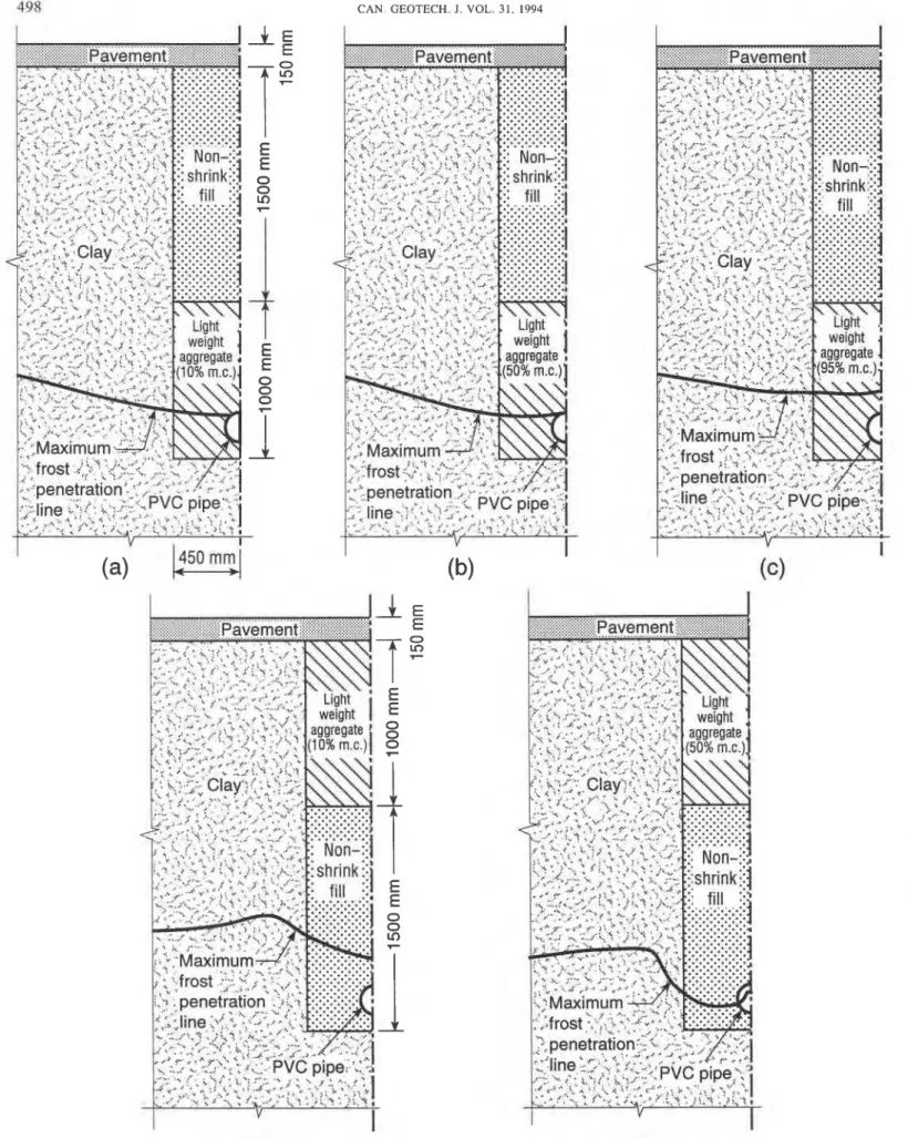
8.4. Insulating backfill - lightweight aggregate
Instead of using insulating layers that, besides increased material cost, entail substantial hand labour, the possibility of an insulating backfill that could be simply dumped into the trenches, with little, or preferably, no compaction, is attrac- tive. Loose granular insulating materials have often been considered as inappropriate for below-ground applications because they inevitably lose their insulating value unless they can be kept dry. For frost-protection applications, how- ever, the increase in apparent thermal conductivity result- ing from the presence of the water can, in principle, be off- set by the increased latent heat available. As a result, in some cases, saturated granular insulations can provide frost protection as good as or better than dry insulation. Expanded clay or shale-based lightweight aggregate is a material of this type that tends to combine a relatively high moisture content with a relatively low thermal conductivity.
Figures 6a-6c show maximum frost-penetration depths calculated for conditions identical to the reference config- uration except that the sand backfill was replaced by light- weight aggregate. The calculations were made for gravi- metric moisture contents of lo%, corresponding to freely drained material; SO%, corresponding to a worst-case scenario of alternate flooding and subsequent draining; and 95%, corresponding to complete saturation.
The results indicate that a 1.0 m thickness appears to be not quite adequate if the material is well drained (the water- line is predicted to begin to freeze). This improves to mar- ginally acceptable at the intermediate moisture content (the frost line just traverses the PVC pipe wall), while under saturated conditions the predicted frost line remains well above the top of the pipe. But it is significant to note that, under saturated conditions, for the same thickness of mate- rial, the predicted frost line remains well above the top of the pipe. Another interesting feature of these results is that, although the intermediate moisture content (Fig. 6b) offers frost protection for the pipe itself similar to that afforded by the fully drained case (Fig. 6a), it shows slightly greater frost penetration within the trench and surrounding soil. This is presumably a consequence of the higher thermal conductivity in the moist case than in the fully drained one, which would result in greater thermal bridging effects through the nonshrinkable fill. But the saturated case (Fig. 6c) shows the least frost penetration of the three cases, both in the trench and in the surrounding native soil zone. The higher thermal conductivity of the lightweight aggregate is more than compensated by the higher latent heat.
It might be anticipated that placing the lightweight aggre- gate layer as high as possible in the trench would produce the greatest benefit. This is to be expected, since the total ther- mal resistance between the surface and the freezing isotherm is at a point augmented by the insulating layer for a greater length of time than it would be if the insulation were placed lower down and, as Fig. 6d illustrates, a substantial gain
appears possible. For Fig. 6d the lightweight aggregate layer was assumed to have properties identical to those of Fig. 6a. It is significant to note that not only is the pipe totally pro- tected from freezing but also frost penetration in the native soil is now shallowest just outside the trench wall. This is a reflection of the fact that during most of the freezing period the frost line would have been higher up within the trench zone than in the native soil. The effectiveness of this geo- metry presumably results from the fact that the insulating fill placed at the top of the trench reduces lateral losses into the coldest zone of the native soil at the same time as it reduces vertical heat losses in the trench. When compared with Fig. 6c, Fig. 6e shows, however, that, for an assumed intermediate moisture content, with lightweight aggregate at least, placing the material high in the trench could lead to greater, not less, frost penetration within the trench itself. This result underscores the importance of maintaining dry conditions if this or similar loose granular materials are to be placed high in the trench. Several possible candidate materials exist that could serve as insulating backfills and fur- ther studies will be carried out.
9. Conclusions
The calculations demonstrate that using combinations of sand and nonshrinkable fill in waterline trenches in wet, fine-grained soils, as has become current practice in the recent past, will result in the occurrence of much more rapid downward freezing within the trench zone than within the sur- rounding native soil. For typical configurations used in Western Canada, the trench could easily freeze to the bottom in a design year and, for no-flow conditions, the waterline would freeze completely. In addition, the enhanced freezing at deep levels also implies the possibility of soil displace- ments in the vicinity of the pipe associated with frost heave. Remedial measures evaluated include modifying the exist- ing design by the addition of polystyrene insulation layers in three different geometrical configurations as well as replace- ment of the sand by insulating backfill materials. The cal- culations showed that full-width horizontal insulating board 50 mm thick would be adequate to stop frost from reach- ing the top of the waterline but also indicated that the ver- tical position within the trench is critical. Placed at the inter- face between the sand and the relatively conductive nonshrinkable fill, the insulation layer is largely bypassed by heat flowing outward from the lower trench zone, and the same insulation thickness becomes inadequate to prevent substantial freezing of the line. The calculations for cylin- drical pipe insulation show that this configuration is very capable of offering adequate protection from freezing for the water inside the line, even the thinnest insulation stud- ied (25 mm) being viable. In addition, this geometry should require the least amount of insulating material of the three cases examined, which could translate into cost savings. But the results also show that this configuration potentially allows frost penetration into the trench bottom directly below the pipe. Inverted U-shaped insulations do offer increased pro- tection from lateral heat losses but, for the wet, fine-grained soil conditions and deep burial depth assumed, this is unnec- essary, and there is no real advantage over horizontal insu- lation while material and labour costs would be greater. Finally, calculations made with the sand at the bottom of the trench replaced by lightweight aggregate show that this or similar granular materials could be viable even when
SEPEHR AND GOODRICH 50 1 wet, since the degradation of thermal insulation is partly
offset by latent heat liberated during freezing. The study concludes, however, that t h e greatest protection can b e achieved by using a dry insulating backfill placed as high as possible in the trench. A summary of results from the analy- sis for various cases is shown i n Table 2.
Chan, H.T., Radhakrishna, H.S., and Klym, T.W. 1981. Insulation for foundations and buried services. In Proceedings of the 10th International Conference on Soil Mechanics and Foundations Engineering, 15-19 June, Stockholm, Sweden. Vol. 1, pp. 69-75.
Coutermarsh, B.A., and Phetteplace, G.E. 1991. Analysis of frost shields using the finite element method. In Proceedings of the 7th International Conference on Numerical Methods in Thermal Problems, Stanford, Calif., July 8-12. Edited by R.W. Lewis, H. Chin, and G.M. Homsy. Pineridge Press, Swansea, U.K. Vol. 7, pp. 122-132.
Crawford, C.B. 1955. Frost penetration studies in Canada as an aid to construction. Roads and Engineering Construction, 93(2): 71-159.
Farag, I.H., Virameteekul, N., and Phetteplace, G. 1991. Phase- change numerical heat transfer analysis with applications to frost shielding. Heat Transfer Engineering, 12(2): 29-36. Goodrich, L.E. 1978. Efficient numerical technique for one-
dimensional thermal problems with phase change. International Journal of Heat and Mass Transfer, 21: 615-621.
Greeley, D. 1987. Design of shallow insulated utility lines - A review. In Proceedings of the 39th Annual Convention of the Western Canada Water and Wastewater Association, Oct. 21-23, Saskatoon, Sask. pp. 249-270.
Gunderson, P. 1975. Frost proofing of pipes. CRREL Dtaft Translation 497, U.S. Army Cold Regions Research and Engineering Laboratory, Hanover, N.H.
Gunderson, P. 1978. Frost protection of buried water and sewage pipes. CRREL Draft Translation 666, U.S. Army Cold Regions Research and Engineering Laboratory, Hanover, N.H. Johnston, G.H. 1981. Permafrost engineering design and con-
struction, National Research Council, Associate Committee of Geotechnical Research. John Wiley & Sons, Toronto. Lunardini, V.J. 1981. Heat transfer in cold climates. Van Nostrand
Reinhold Company, New York.
Morgan, K., Lewis, R.W., and Zienkiewicz, O.C. 1978. An improved algorithm for heat conduction problems with phase change. International Journal for Numerical Methods in Engineering, 12: 1191-1 195.
Sasaki T. 1985. Frost damage of water conduits. In Proceedings of the 4th International Symposium on Ground Freezing, Aug. 5-7, Sapporo, Japan. Vol. 2. pp. 329-334.
Smith D.W. (Editor) 1986. Cold climate utilities delivery design manual. Environment Canada, Environmental Protection Service, Report EPS-3-WP-79-2.