Applications of Axial and Radial
Compressor Dynamic System Modeling
by
Zoltin S. Spakovszky
S.B., Mechanical Engineering, Eidgen6ssische Technische Hochschule (ETH) Zurich (1996)
S.M., Mechanical Engineering, Eidgen5ssische Technische Hochschule (ETH) Znrich (1997) S.M., Aeronautics and Astronautics, Massachusetts Institute of Technology (1999)
Submitted to the Department of Aeronautics and Astronautics in partial fulfillment of the requirements for the degree of
Doctor of Philosophy
at the
Massachusetts Institute of Technology
February 2001
@ Zoltin S. Spakovszky, 2000. All rights reserved.
palmI gfon. to reprduce and to diitute pubf poe
Author
g' Departnlent 0 Aeronautics and /stronautics Decerd r 2,, 2000
Certified by
James D. Paduano Principal Research Engineer, Ph.D., Committee Cgairman
Certified by
Alan H. Epstein R. C. Maclaurin Professor of Aeronauics and Astronautics
Certified by
Edward M. Greitzer
H.N. Slater Professor of Aeronautics and Astronautics
, - -A
Accepted by
MASSACHUSETTS____________ Wallace E. Vander Velde
MASSACHOSETTS
ITIT
Professor of Aeronautics and AstronauticsOEC
112001
AEROChairman,
Department Graduate CommitteeSEP 11 20
Applications of Axial and Radial
Compressor Dynamic System Modeling
by
Zoltin S. Spakovszky
Submitted to the Department of Aeronautics and Astronauticson December 22, 2000, in partial fulfillment of the requirements for the degree of Doctor of Philosophy
Abstract
The presented work is a compilation of four different projects related to axial and centrifugal compression systems. The projects are related by the underlying dynamic system modeling approach that is common in all of them. Two types of models are introduced, suitable for modeling the dynamic behavior of axial and centrifugal compression systems: a compact single semi-actuator disk model, Model I, and a new modular multi semi-actuator disk model, Model II.
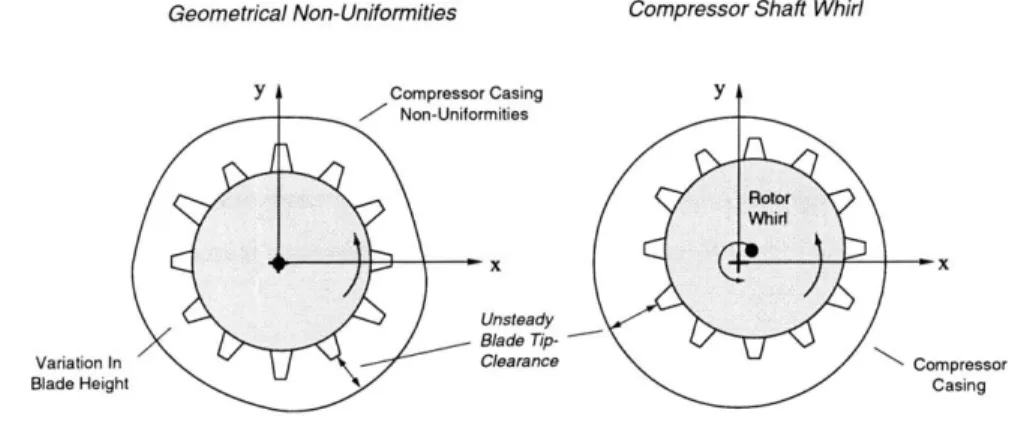
The first project analyzes aerodynamically induced whirling forces in axial-flow compressors and a new unsteady low order model is introduced to predict the destabilizing whirling forces. The model consists of two parts: compressor Model I with the effect of tip-clearance induced distortion, and an aerodynamically induced force model. The modeling results are compared to experimental data obtained from the GE Aircraft Engines test program on compressor whirl. Previously outstanding whirl-instability issues are resolved, including prediction of the direction and magnitude of rotor whirl-inducing forces; such issues are important in the design of modern axial-flow compressors. Additional insight is gained from the model on the effects of forced rotor whirl. In particular, a non-dimensional parameter is deduced that determines the direction of rotor whirl tendency in both compressors and turbines due to tangential blade loading forces.
The second project is a first-of-a-kind feasibility study of an active stall control experiment with a mag-netic bearing servo-actuator in the NASA Glenn high-speed single-stage compressor test facility. Together with CFD and experimental data the tip-clearance sensitive compressor Model I was used in a stochastic estimation and control analysis to determine the required magnetic bearing performance for compressor stall control. A magnetic bearing servo-actuator was designed that fulfilled the performance specifications, setting a milestone in magnetic bearing development for aero-engine applications. Control laws were then developed to stabilize the compressor shaft. In a second control loop, a constant gain controller was imple-mented to stabilize rotating stall. A detailed closed loop simulation at 100% corrected design speed resulted in a 2.3% reduction of stalling mass flow which is comparable to results obtained in the same compressor using unsteady air injection.
The third project is the investigation of unsteady impeller-diffuser interaction effects on compressor stability. First, the unsteady blade-row interaction in axial compressors is analyzed using Model II. The results reveal a new signature of pre-stall waves that travel backward, altering the system dynamics when rotor and stator are moderately coupled. The physical mechanism for this behavior is explained from first principles and a coupling criterion is presented. The theory is then applied to centrifugal compressors and in particular to the NASA CC3 high-speed centrifugal compressor, in which experiments are conducted to verify the model predictions. The measurements show the predicted behavior and confirm the existence of backward traveling stall pre-cursors.
The fourth project is an experimental demonstration of stability enhancement in the NASA CC3 high-speed centrifugal compressor with air injection. Based on model predictions an air injection scheme in between the impeller and the vaned diffuser of the centrifugal compressor is designed and tested. The mechanism of surge inception in this machine is explained and the injection results show an increase of 25% in surge-margin with an injection mass flow of 0.5% of the compressor design mass flow.
Thesis Supervisor: James D. Paduano Title: Principal Research Engineer, Ph.D.
a drdga sziileimnek, is az iletem szerelminek
- az ides picikimnek
Acknowledgments
Throughout the course of my appointments at MIT's Gas Turbine Laboratory, starting as a visiting research engineer, I had the opportunity to meet and to interact with many different people from various organiza-tions, both in industry and in academia. Without this great experience and the support and encouragement of many people, I would not have arrived at this position and stage of my life.
At MIT, I am greatly indebted to the members of my committee and all the people who were of great help during my projects. I would like to thank Dr. Jim Paduano for his tremendous support and for the best teamwork, Dr. Fred Ehrich for all his advice as an expert on rotordynamics, Dr. Gerald Guenette for the greatest ideas whenever an experiment had to be designed and Prof. Eric Feron for his insightful discussions on control related issues. I wish to thank Professor Ed Greitzer for being an invaluably inspiring mentor and for always challenging me to think "deeper". I am also greatly indebted to Professor Alan Epstein for being always interested and supportive and for giving me the initial opportunity to do research at the Gas Turbine Laboratory. I would like to thank Ammar, Ken, Shengfang and Yifang for the very helpful discussions and Victor and Jimmy for their help at the machine shop. Many thanks go also to Lori for all her help and for making GTL "workable" and a place with soul. Special thanks go to my best friends on whom I can always count and with whom I share a unique friendship: Adam, Amit, Chris, Constantine, Erik, Luc, and Rory - guys, we will make it happen!
At the Whittle Laboratory, I would like to thank Professor Nick Cumpsty for the most inspiring discus-sions and Dr. Tom Hynes for his insightful comments and for sharing data with me. At Caltech, I wish to thank Professor Frank Marble for the very helpful discussions and for always shedding a different light on things. Many thanks go also to Professor Luis San Andres at Texas A&M for his input and expertise on squeeze film dampers, and to Professor Seung-Jin Song at Seoul National University for sharing data with me. At ETH Zurich, I wish to thank all my friends at the turbomachinery laboratory, Andy, Chris-tian, Dirk, Ernesto, H6lene and Andr6, Joey, Michael and Pascal, and Professor Gyarmathy to whom my personal admiration goes. I would like to thank my best buddies Damian ("Digge") at the Royal Institute of Technology in Stockholm for sharing views on engineering and philosophy, Michael ("Jesse") at Swissair Technics, and Jens and Steff for all the great times we had and the times to come.
At the NASA Glenn Research Center, I am most greatly indebted to Dr. Tony Strazisar and Dr. Michelle Bright. I would like to thank them for their support and encouragement and for sharing many great experiences as the "three kuchinas" during the various projects at NASA and at Allied Signal Aerospace. I also wish to thank Gary Skoch and Jerry Wood for the very interesting discussions and for their help on the CC3 project. Special thanks go to the crew in CE-18: Tony Zaldana and Tom Jett for getting the rig up and running, Scott Panko and Harry Fuller for making sure (not) all Kulites, amps and filters were working, and Mark Stevens for the most amazing technical design drawings that made it possible to fit all instrumentation on the rig. Many thanks go also to Ken Suder, Michael Hathaway, Dale Van Zante, Sue Prahst, Don Simon, Scott Thorp, Al Kascak, Gerald Brown, Julius Giriunas, Ralph Jansen, Rick Brokopp
and Dave ("Willy") Williams.
At Pratt & Whitney, I am most grateful to Dr. Om Sharma with whom my journey to the United States all began. His interest and trust made it possible for me to reach higher grounds. I also would like to thank Dr. Jeff Gertz and Urs Glarner for their friendship and all the great times at Pratt and at Swissair.
At GE Aircraft Engines, I wish to thank Dr. Dave Wisler for his support and for giving me the opportunity to work on the GE compressor whirl project. Many thanks go also to Dr. Hyoun-Woo Shin, Al Storace and Brent Beacher for collecting and sharing data with me.
At MECOS Traxler AG, I am greatly indebted to Dr. Alfons Traxler and Dr. Ren6 Larsonneur for their invaluable help in the final design of the MB actuator and from whom I have learned so much more about magnetic bearings.
At Scientific Systems Company Inc., I would like to thank Dr. Chris van Schalkwyk for the many great discussions on system identification and for sharing software with me.
Finally I am most grateful to my parents and my brother for their love and personal support and for always encouraging me to go my own ways. All my love goes to Wiebke with whom I share my entire heart and soul, and who turned my life into an eternal dream -6des kicsi-mamdm, 6des apdm, Sdndi 6s picik6m
- k6szdn6m sz6pen!
This research was conducted under NASA grant NAG3-1457, Dr. M. Bright program manager. This support is gratefully acknowledged.
Contents
Abstract 3 Acknowledgements 7 List of Figures 21 List of Tables 23 Nomenclature 25 1 Introduction 33 1.1 Thesis O verview . . . . 342 Dynamic Compression System Modeling 39 2.1 Compression System Definition . . . . 40
2.2 Model I: Compact Single-Actuator Disk Approach . . . . 41
2.2.1 Calculation of the Steady Flow Field . . . . 43
2.2.2 Unsteady, Small Amplitude Flow Perturbations: State-Space Form of Model . . . . 43
2.3 Model II: New, Modular Multi-Actuator Disk Approach . . . . 49
2.3.1 Axial Duct Flow Dynamics . . . . 50
2.3.2 Swirling Flow Dynamics . . . . 53
2.3.3 Rotor/Impeller Actuator Dynamics . . . . 57
2.3.4 Stator/Diffuser Actuator Dynamics . . . . 63
2.3.5 Transmission Matrix Stacking . . . . 67
2.3.6 Boundary Conditions . . . . 68
2.3.7 The Eigenvalue Equation -A Dispersion Problem . . . . 70
2.4 Numerical Procedures for the Dispersion Problem . . . . 70
2.4.1 Graphical Procedure: The Contour Plot Method . . . . 70
2.4.2 Numerical Procedure: The Shot-Gun Method . . . . 71
2.5.1 Example I: Classical Moore-Greitzer Formulation . . .
2.5.2 Example II: Jet-Wake Type Flow Perturbations in a V
2.6 Sum m ary . . . .
3 Analysis of Aerodynamically Induced Whirling Forces in ) 3.1 Introduction and Background . . . .
3.2 Research Questions . . . .
3.3 GE Aircraft Engines Experimental Program On Compressor 3.3.1 GE Low Speed Research Compressor (LSRC) . . . . . 3.3.2 Tip-Clearance Conditions . . . . 3.3.3 LSRC Instrumentation and Data Reduction . . 3.4 Modeling Approach . . . . 3.4.1 Unsteady Compressor Tip-Clearance Model I . 3.4.2 Aerodynamically Induced Force Model . . . . . 3.5 Analysis of Experimental Results . . . . 3.5.1 Importance of the Alford
#
Parameter . . . . . 3.5.2 Blade Loading Indicator Parameter . . . . 3.5.3 Effects of Spool Pressure Loading . . . . 3.5.4 Effects of Forced Shaft Whirl . . . . 3.6 Conclusions and Summary . . . .4 Tip-Clearance Actuation With Magnetic Bearings Control
4.1 Background . . . . 4.2 Research Questions . . . . 4.3 Organization of Chapter . . . . 4.4 Axial Compressor Rig Specifications . . . . 4.5 Preliminary Analysis . . . . 4.5.1 Simplified Rotordynamic Design and Analysis 4.5.2 Analysis of Tip-Clearance Control Authority 4.6 Design Requirements . . . . 4.7 Magnetic Bearing Servo-Actuator Design . . . . 4.7.1 Electro-Magnetic Actuator Analysis . . . . 4.7.2 Overall Dynamic System Analysis -Achievable 4.7.3 Heat Loss and Cooling Analysis . . . . 4.8 Closed Loop Stall Control Simulation . . . . 4.9 Summary and Concluding Remarks . . . .
aneless Diffuser . . . . Axial Vhirl Compressors 73 76 79 81 81 83 84 84 85 85 87 87 89 92 92 93 96 99 102
For High-Speed Compressor Stall 105 . . . . . 105 . . . . . 106 . . . . . 106 . . . . . 107 . . . . . 109 . . . . . 109 . . . . . 118 . . . . . 127 . . . . . 128 . . . . . 128 . . . . . 131 . . . . . 134 . . . . . 135 . . . . . 136 Whirl Radii
5 Analysis of Unsteady Impeller-Diffuser Interaction Effects on Compressor Stability
5.1 Background ... ...
5.2 Research Questions and Objectives . . . .
5.3 Organization of Chapter . . . . 5.4 Analysis of Unsteady Blade-Row Interaction Effects on Axial Compressor System Stability
5.4.1 Pre-Stall Modes in an Isolated Stator Blade-Row . . . . 5.4.2 Pre-Stall Modes in an Isolated Rotor Blade-Row . . . . 5.4.3 Pre-Stall Modes in Interacting Rotor-Stator Blade-Rows . . . .
5.5 Physical Mechanism For Blade-Row Interaction Effects on Compressor System Stability . . 5.5.1 First Principles Approach for Backward Traveling Pre-Stall Waves . . . . 5.5.2 Physics Underlying the Strong Interaction Regime . . .
5.5.3 Physics Underlying the Moderate Interaction Regime . . 5.5.4 Physics Underlying the Weak Interaction Regime . . . . 5.6 Impeller-Diffuser Interaction Effects on Centrifugal Compressor P redictions . . . . 5.6.1 NASA CC3 High-Speed Centrifugal Compressor . . . . 5.6.2 Model II Implementation . . . . 5.6.3 Model II Predictions . . . . 5.6.4 Model II Based Design of Diffuser Air Injection Nozzles 5.7 Experimental Validation of Model II Predictions . . . . 5.8 Implications of Unsteady Blade-Row Interaction Effects . . . . 5.8.1 Compressor Design for Enhanced Operational Stability 5.8.2 Turbomachinery Noise -Aero-Acoustics . . . . 5.9 Summary and Conclusions . . . .
6 High-Speed Centrifugal Compressor Stability Enhanceme
tion
6.1 Background . . . . 6.2 Research Questions and Objectives . . . . 6.3 Organization of Chapter . . . . 6.4 Experimental Setup and Test Facility . . . . 6.4.1 Test Facility Overview . . . . 6.4.2 NASA CC3 High-Speed Centrifugal Compressor . . . . 6.4.3 Air Injection Actuation and Instrumentation . . . . 6.4.4 Data Acquisition . . . . 6.5 Mechanism of Surge Inception in the NASA CC3 High-Speed C
139 139 141 141 142 142 144 146 151 155 161 162 164 System Stability: Model II
. . . . 16 4 . . . . 16 4 . . . . 16 5 . . . . 16 8 . . . . 17 0 . . . . 1 7 2 . . . . 17 6 . . . . 1 7 6 . . . . 1 78 . . . . 1 79
Using Diffuser Air Injec-181 . . . . 181 . . . . 182 . . . . 183 . . . . 183 . . . . 183 . . . . 185 . . . . 185 . . . . 189 entrifugal Compressor . . . 189
6.5.1 Unsteady Compressor Pre-Stall Behavior at 80% Speed . . . . 189 nt
6.5.2 Unsteady Compressor Pre-Stall Behavior at 100% Speed . . . 195
6.5.3 Mechanism of Surge Inception . . . . 199
6.5.4 Pathology of Surge . . . . 200
6.6 Baseline Steady-State Compressor Performance . . . 203
6.6.1 Vaned Diffuser Performance . . . . 204
6.7 Steady Air Injection Results With Vaneless Space Nozzles . . . . 207
6.7.1 Effects of Air Injection in the Vaneless Space on Impeller and Diffuser Performance. 213 6.8 Steady Air Injection Results With Diffuser Passage and Diffuser Vane Nozzles . . . 215
6.8.1 Diffuser Passage Nozzles . . . 215
6.8.2 Diffuser Vane Nozzles . . . 217
6.9 Steady Air Injection Results With Impeller Inlet Nozzles . . . . 218
6.10 Viability Assessment of Vaneless Space Injection in Working Engine Environments . . . . . 222
6.10.1 Stability Enhancement with Increased Impeller Tip-Clearance . . . . 222
6.10.2 Stability Enhancement with Reduced Number of Vaneless Space Air Injectors . . . . 223
6.10.3 Recovery From Fully Developed Surge With Air Injection . . . . 225
6.11 Summary and Conclusions . . . . 226
6.12 Future Work: Recommendations For Active Surge Control . . . 228
6.12.1 1-D Sound Attenuation Using Single Channel Feedforward Control . . . 228
6.12.2 A Feedforward Active Surge Control Scheme Using Adaptive Digital FIR Filters 232 7 Summary and Contributions of the Thesis 235 7.1 Summary and Conclusions of the Projects . . . . 235
7.2 Thesis Contributions . . . . 239
A Matlab Codes 241 A.1 Transmission M atrix Tax,n . . . . 241
A.2 Transmission M atrix Trad,n . . . . 242
A .3 Radial Functions . . . 243
A.4 Model II of NASA CC3 Compressor: Main Routine Using Shot-Gun Method . . . 244
A.5 Model II of NASA CC3 Compressor: Main Routine Using Contour Plot Method . . . . 247
B Adaptive Digital FIR Filter 251
List of Figures
2-1 Axial-centrifugal compression system: the GE (formerly Honeywell, formerly Allied Signal, formerly Textron, formerly Avco and formerly Lycoming) T55 L-5 core engine. . . . . 2-2 Modeled components of compact model formulation. . . . .
2-3 Compression system model with air injection actuation. . . . . 2-4 Unsteady compressor blade tip-clearance due to geometrical non-uniformities and shaft whirl. . .
2-5 2-6 2-7 2-8 2-9 2-10 2-11 2-12 2-13 2-14 2-15
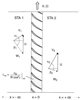
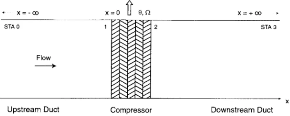
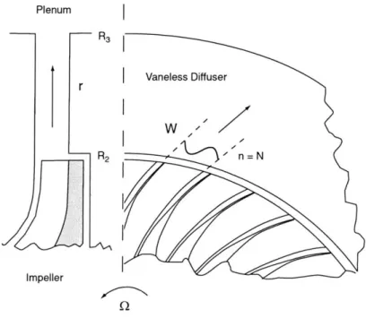
Free vortex mean flow for - = 5 with zero net rotation such that = 0. . . . . Actuator disk model for an axial rotor blade row. . . . . Actuator disk model for a radial impeller. . . . . Actuator disk model for an axial stator blade row . . . . . Actuator disk model for a radial vaned diffuser. . . . . Actuator disk model for a radial vaneless diffuser. . . . . Single-stage axial compressor model. . . . . Contour plot m ethod. . . . . Shot-gun m ethod. . . . . Classical Moore-Greitzer model approach for a generic axial compressor. . . . . Classical Moore-Greitzer formulation for a generic axial compressor: analytical solution (o), shot-gun method solution (+) and contour plot method solution using Model 11 for spatial harmonics
1, 2 and 3... ...
2-16 Schematic of vaneless diffuser with jet-wake flow non-uniformity. . . . .
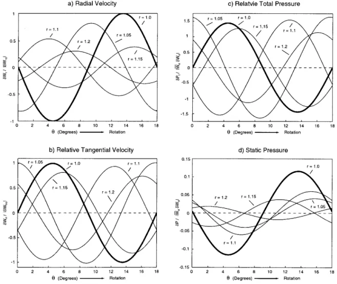
2-17 Model il results: behavior of fundamental flow disturbances (n = 20) in vaneless diffuser for
Q = 0.215 and
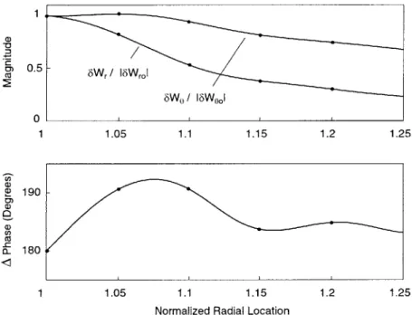
I = 0.7032. . . . .2-18 Top: magnitude of radial and relative tangential velocity perturbations; bottom: phase difference
between radial and relative tangential velocity perturbations . . . .
3-1 3-2 3-3
Aerodynamically induced forces on a compressor rotor. . . . .
GE Aircraft Engines Low Speed Research Compressor .. . . . . Cross section of the GE LSRC test compressor stage. . . . .
3-4 Experimentally measured unsteady static pressure difference on the rotor blade surface for a shaft
offset of AE = 1.66%, time instant of minimum clearance ([181). . . . . 86
3-5 Tip-clearance compressor model overview. . . . . 87
3-6 LSRC compressor characteristics for two axisymmetric tip-clearance levels and compressor perfor-mance for a steady shaft offset of Ae = 0.7%: experimental measurements and model prediction. 88 3-7 Definition of reference frames: rotor frame (x", y"), rotating asymmetry frame (x', y') and abso-lute fram e (x, y). . . . . 90
3-8 Unsteady momentum control volume analysis locked to rotor frame. . . . . 90
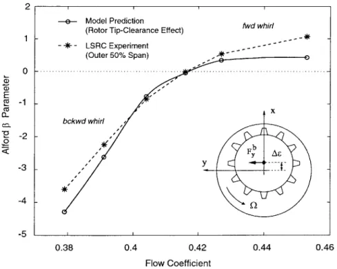
3-9 Experimental prediction and model results of the Alford
#
parameter for the GE LSRC compressor. 92 3-10 Simplified blade loading analysis for compressors and turbines. . . . . 933-11 Simplified whirl analysis of the GE LSRC compressor. . . . . 95
3-12 Circumferential static pressure distribution obtained from the model at mid-span and a rough experimental estimate of the passage pressure non-uniformity. . . . . 97
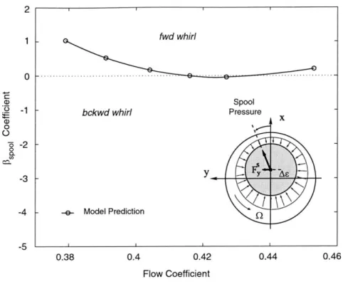
3-13 Spool loading parameter 3spool for the GE LSRC compressor. . . . . 98
3-14 Effect of flow inertia on rotor forces due to spool pressure loading. . . . . 99
3-15 Compressor flow field with inertia effects included (solid) and inertia effects neglected (dashed) for a given tip-clearance distribution &e (dotted). . . . . 99
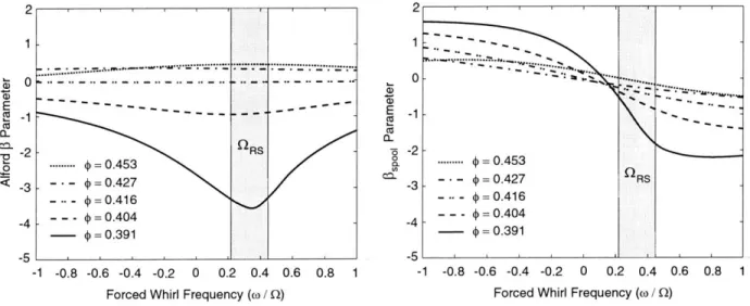
3-16 Alford 0 parameter and spool loading parameter 3spool for forced rotor whirl. . . . . 100
3-17 Magnitude and phase of fundamental wave form of flow coefficient (solid) and non-dimensional spool pressure (dash) for # = 0.391. . . . . 101
4-1 Active tip-clearance stall control concept. . . . . 106
4-2 Design process for an axial compressor magnetic bearing system. . . . . 107
4-3 NASA Glenn high-speed single stage compressor test facility. . . . . 108
4-4 Preliminary magnetic bearing compressor rotor and corresponding lumped parameter model. . . 109
4-5 T hin rigid disk m odel. . . . . 110
4-6 Transverse deformation of a flexible shaft segment. . . . . 111
4-7 Flexible uniform shaft segment with distributed mass. . . . . 113
4-8 Integral Squeeze Film Damper (ISFD) with flexure pivot tilting pad journal bearing (courtesy of Texas A & M ). . . . . 116
4-9 Preliminary open loop rotor model eigenvalues: forward whirling (+), backward whirling (x). . . 117
4-10 Transfer function Grotor(s) from magnetic bearing force input 6fb to blade tip deflection &. . . 117
4-11 Computed compressor rotor mode shapes. . . . . 117
4-12 Closed loop magnetic bearing compressor system for stall control. . . . . 119
4-13 Model I approach with tip-clearance and air injection actuation. . . . . 120
4-14 C-coil electro-m agnet. . . . . 121
4-16 Preliminary magnetic bearing servo-actuator performance: transfer function AMB(S) from com-manded blade deflection 6c to actual blade deflection &e. . . . . 123
4-17 Spectral analysis of open loop pre-stall pressure perturbations (experiment by Weigl et al. [96]) and of open loop compressor Model I. . . . . 124 4-18 Open loop compressor dynamics (x) and closed loop poles with constant gain control (+). . . . 125 4-19 Maximum static magnetic force per C-coil pair of a 16 pole configuration. . . . . 128
4-20 Pole configuration with rotor laminations and dimensions of magnetic bearing servo-actuator ([48]).129 4-21 Campbell diagram of magnetic bearing servo-actuator obtained from finite element rotordynamic
model ([48]). Forward and backward whirling modes are marked solid and dashed respectively. . 132
4-22 Left: current-force characteristic of magnetic bearing servo-actuator and operating locus; right: achievable whirl radii at several shaft locations and amplifier operation limits ([48]) . . . . 133
4-23 Detailed design layout of magnetic bearing servo-actuator and facility interfacing ([48]). . . . . 135
4-24 Simulated NASA Stage 37 compressor characteristic at design speed. The stall points with magnetic bearing tip-clearance actuation and no control are marked with (o) and (*) respectively. 136
5-1 Isolated stator blade-row with upstream swirl. . . . . 142
5-2 Isolated rotor blade-row with exit swirl. . . . . 145
5-3 Interacting rotor and stator blade-rows. . . . . 146 5-4 Rotor-stator system eigenvalues for a non-dimensional blade-row spacing of Ax = 0.3. The
spatial harmonics are numbered next to the modes. . . . . 148
5-5 System eigenvalues for an isolated rotor blade-row (squares), an isolated stator blade-row
(dia-monds) and a closely coupled rotor-stator system (stars) with Ax = 0. . . . 149
5-6 Motion of third harmonic (n = 3) system eigenvalues of interacting rotor-stator system for variable
inter-blade row spacing Ax = 0..1 and analytical solutions for limiting cases: Moore-Greitzer
solution (star), isolated rotor (square) and isolated stator solution (diamond). . . . . 150 5-7 Bifurcation-like diagram for third harmonic (n = 3) system eigenvalue of interacting rotor-stator
system for variable inter-blade row spacing Ax = 0.1. . . . . 151 5-8 Thought experiment: device with unknown properties yielding backward traveling system mode. 152 5-9 Four-dimensional domain [r, P, ZR, ZI] where device properties are such that the backward
trav-eling wave s = -0.22 - j(-0.17) exists. . . . . 153 5-10 Mode shapes of axial velocity perturbation (a) and static pressure perturbation (b) for third
harmonic system mode s = -0.22 - j(-0.17) from Model 11. . . . 154
5-11 Wave system for interacting rotor and stator blade-rows. . . . . 155 5-12 Gain and phase relation between pressure perturbation 11 impinging on rotor and generated
vorticity ( . . . . . 158
5-13 Gain and phase relation between vorticity perturbation 6 impinging on stator and reflected pres-sure perturbation . . . . 160
5-14 Gain and phase matching of pressure perturbation transmitted through rotor '2r""' (dash) and pressure perturbation reflected from stator face pref2 (solid) at a negative frequency of w
-0.24. Third harmonic (n = 3) pressure perturbations at x = 0 for rotor-stator spacing of
Ax = 0.433. ... ... 161 5-15 NASA CC3 high-speed centrifugal compressor. . . . . 165 5-16 NASA CC3 impeller and diffuser loss characteristics. . . . . 167 5-17 1st through 6th harmonic system modes of NASA CC3 centrifugal compressor for an operating
point close to stall. Contour plot method for n = 1 is marked as solid and lightly dashed lines. . 168 5-18 Energy function for first through fourth harmonic eigenvalues marked as diamonds in Figure 5-17. 169 5-19 Motion of system modes when compressor is throttled into stall (eigenvalues for the two operating
points shown on characteristic). Impeller modes are marked as squares and diffuser modes are marked as open diamonds. . . . . 170
5-20 Nozzle configurations for diffuser injection: (a) vaneless space nozzle (Model
11
based design),(b) diffuser vane nozzle and (c) diffuser passage nozzle. . . . . 171 5-21 Unsteady pressure traces in the vaneless space during a stall ramp at 80% corrected design speed,
solid shroud (no injection). . . . . 172
5-22 Unsteady pressure traces in the vaneless space during a stall ramp at 100% corrected design speed,
solid shroud (no injection). . . . . 173
5-23 Unsteady pressure signals during a stall ramp at 80% corrected design speed. Pressure traces at
impeller inlet, in the vaneless space, at the diffuser throat and in the diffuser passage at mid chord.174 5-24 Diffuser static pressure rise and slope of static pressure rise at 80% corrected design speed for
vari-ous injection schemes: no injection (circles), diffuser injection using tangential nozzles (diamonds) and im peller injection (squares). . . . . 175 5-25 Unsteady pressure traces in the vaneless space during stall ramps at 80% corrected design speed
with (a) diffuser injection using tangential nozzles (diamonds in Figure 5-24) and impeller injection (squares in Figure 5-24). . . . . 175
5-26 Snapshot from an unsteady 2-dimensional Euler calculation in a commercial fan stage. Rotor
blades move to the left and a 3rd harmonic static pressure wave in the axial gap propagates to the right against the direction of rotor rotation (courtesy of Hynes [40]). . . . . 178
6-1 NASA Glenn Research Center's CE-18 high-speed centrifugal compressor test facility. . . . . 183 6-2 Test section showing air injection supply, impeller casing and diffuser shroud with air injector
actuators and Kulite sensors (top). Cross section of CC3 centrifugal compressor depicting impeller and diffuser injection schemes (bottom). . . . . 184
6-3 Impeller injection scheme (front view of impeller casing and diffuser shroud). . . . . 186
6-4 Three different diffuser nozzle types: diffuser passage nozzle, diffuser vane nozzle and vaneless
6-5 Diffuser injection scheme and Kulite instrumentation (front view of vaned diffuser) shown with 8
vaneless space nozzles. . . . . 188
6-6 Impeller inlet Kulites: unsteady pressures traces and corresponding spectrograms of Oth, 1st, 2nd, 3rd and 4th spatial harmonic pressure perturbations during a stall ramp at 80% corrected design
speed. ... ... 190
6-7 Vaneless space Kulites: unsteady pressures traces and corresponding spectrograms of Oth, 1st, 2nd, 3rd and 4th spatial harmonic pressure perturbations during a stall ramp at 80% corrected design speed. ... ... 192 6-8 Diffuser throat Kulites: unsteady pressures traces and corresponding spectrograms of Oth spatial
harmonic pressure perturbations during a stall ramp at 80% corrected design speed. . . . . 193 6-9 Harmonic content of traveling energy of the first four pre-stall modes at impeller inlet, vaneless
space and diffuser throat at 80% corrected design speed. . . . . 194
6-10 Impeller inlet Kulites: unsteady pressures traces and corresponding spectrograms of Oth, 1st, 2nd, 3rd and 4th spatial harmonic pressure perturbations during a stall ramp at 100% corrected design
speed. ... ... 196
6-11 Vaneless space Kulites: unsteady pressures traces and corresponding spectrograms of Oth, 1st, 2nd, 3rd and 4th spatial harmonic pressure perturbations during a stall ramp at 100% corrected design speed. ... ... 197 6-12 Diffuser throat Kulites: unsteady pressures traces and corresponding spectrograms of Oth spatial
harmonic pressure perturbations during a stall ramp at 100% corrected design speed. . . . . 198 6-13 Harmonic content of traveling energy of the first four pre-stall modes at impeller inlet, vaneless
space and diffuser throat at 100% corrected design speed. . . . . 198
6-14 Pressure traces at impeller inlet, in the vaneless space, at the diffuser throat and in the diffuser passage along the path into instability at 80% corrected design speed (left) and at 100% corrected design speed (right). . . . . 199
6-15 "Classic surge": pressure traces in the vaneless space at 80% corrected design speed. . . . . 201
6-16 Pressure traces at impeller inlet, in the vaneless space, at the diffuser throat and in the diffuser
passage during a surge cycle at 80% corrected design speed (left) and closer view of phases A, B and C (right). . . . . 201
6-17 NASA CC3 centrifugal compressor map with speed lines at 80% and 100% corrected design speed
and impeller total-to-static pressure ratio characteristics at the same speeds . . . . 203 6-18 Overall diffuser performance at a) 80% corrected design speed, and b) 100% corrected design
speed and static pressure rise of its sub-components such as vaneless space, semi-vaneless space and diffuser passage. . . . 205
6-20 Speed lines at 80% and 100% corrected design speed with vaneless space injectors (diamonds)
and no injectors (circles). A total steady injector mass flow of 0.5% of the compressor design mass flow yields and increase in surge-margin of 23% at part speed and 27% at design speed respectively. . . . . 208
6-21 Vaneless space injectors: overall diffuser performance at a) 80% corrected design speed, and b) 100% corrected design speed and static pressure rise of its sub-components such as vaneless
space, semi-vaneless space and diffuser passage. . . . . 209 6-22 Impeller total-to-static pressure ratio with no injection (circles) and with vaneless space injection
(diamonds) for 80% and 100% corrected design speed . . . . 210
6-23 Pressure traces in the vaneless space during a stall ramp with air injection in the vaneless space
at 100% corrected design speed. . . . . 211 6-24 Impeller inlet Kulites with air injection in the vaneless space: unsteady pressures traces and
corresponding spectrograms of Oth, 1st, 2nd, 3rd and 4th spatial harmonic pressure perturbations during a stall ramp at 100% corrected design speed. . . . . 212
6-25 Velocity triangles at the impeller exit near the diffuser shroud (solid) and near the diffuser hub
(dash). The air jet from the tangential injector nozzle is sketched as the dotted line. The vaneless space is not to scale. . . . . 213
6-26 Impeller total-to-static pressure ratio (left) and diffuser sub-component pressure rise at the hub
(center) and at the shroud (right) for no injection (white symbols) and injected mass flows of
0.8% (grey symbols) and 1.6% of compressor design mass flow (black symbols) at 100% corrected
design speed. ... ... 214
6-27 Diffuser sub-component pressure rise at the hub (left) and at the shroud (right) for no injection
(white) and an injected mass flow of 0.68% (grey) with diffuser passage nozzles at 100% corrected design speed. ... ... 216 6-28 Diffuser sub-component pressure rise at the hub (left) and at the shroud (right) for no injection
(white) and an injected mass flow of 0.72% (grey) with diffuser vane nozzles at 100% corrected design speed. ... ... 217 6-29 Speedlines at 80% and at 100% corrected design speed with no injection (circles) and using
impeller inlet injection (squares) with choked nozzles (1.43% injection mass flow at part speed and 1.53% injection mass flow at design speed). . . . . 218 6-30 Impeller total-to-static pressure ratio with no injection (circles) and with impeller inlet injection
(diamonds: unchoked nozzles, squares: choked nozzles) for 80% and 100% corrected design speed.219
6-31 Impeller inlet injectors: overall diffuser performance at a) 80% corrected design speed, and b) 100% corrected design speed and static pressure rise of its sub-components such as vaneless
space, semi-vaneless space and diffuser passage with no injection (circles) and with impeller inlet injection (diamonds: unchoked nozzles, squares: choked nozzles). . . . . 220
6-32 Summary of stability enhancement at 80% and at 100% corrected design speed using the vaneless
space nozzle configuration (diamonds), the diffuser vane (circles) and the diffuser passage nozzle configuration (triangles) and the impeller inlet nozzle configuration (squares). . . . . 221
6-33 Effect of impeller exit tip-clearance on surge-margin and on stability enhancement at 80% and at 100% corrected design speed with vaneless space injectors. Design tip-clearance (2.4% of passage
height) is marked with circles and solid lines, increased tip-clearance (3.6% of passage height) is marked with diamonds and dashed lines. . . . . 223
6-34 Summary of stability enhancement at 80% and at 100% corrected design speed using all 8 (di-amonds) and a reduced number of vaneless space injectors: 6 injectors (squares), 4 injectors (circles) and 4 asymmetrically arranged injectors (triangles). . . . . 224
6-35 Recovery from fully developed surge with vaneless space air injection at 80% corrected design
speed and constant throttle setting. . . . . 226 6-36 Sound attenuation in a pipe using single channel feedforward control: physical system (top) and
block diagram (bottom ). . . . . 229
6-37 Simplification of block diagram in Figure 6-36 as a conventional least squares estimation problem. 229 6-38 Feedback cancellation scheme (left) and IIR filter approach (right). . . . . 230 6-39 FIR filter design problem (left) and block diagram of a LMS adaptive FIR filter (right). . . . . . 230
6-40 Feedforward active surge control scheme using adaptive digital FIR filters for one actuator and a pair of adjacent Kulite pressure sensors. . . . . 232
List of Tables
3.1 Non-dimensional LSRC geometry and model input parameters. . . . . 87 3.2 LSRC blade row geometry. . . . . 88
3.3 Experimental results and Ab approach for the GE LSRC compressor and three axial flow com-pressors reported in Ehrich [17]: backward whirl tendency for
4
<4o,
forward whirl tendency for4
>4,.
* experimentally based predictions by Ehrich [17]. . . . . 963.4 Experimental result and Ab approach for the SSME liquid hydrogen turbopump 1st turbine stage. 96
4.1 Inertia properties of modeled elements. . . . . 115
4.2 Support stiffness and damping coefficients . . . . 116
4.3 Simulated and measured RMS of injector valve motion. . . . . 126
4.4 Optimized magnetic bearing servo-actuator design parameters ([48]). . . . . 130
4.5 Total mechanical, electro-magnetic and aerodynamic losses at 286 Hz design speed ([48]). . . . 134
5.1 Generic rotor and stator geometry and performance. . . . . 147
5.2 NASA CC3 compressor flow path geometry, non-dimensionalized by impeller exit radius R2. . . 166
5.3 NASA CC3 impeller and diffuser blade-row geometry and blade passage inertia. . . . . 166
5.4 Model
Il result compared to experimental measurements at 80% and 100% corrected design speed.173
6.1 Circumferential location of impeller injectors and impeller Kulite sensors (angles in direction of
rotation)... ... 186
6.2 Circumferential and radial location of diffuser injectors and Kulite sensors (angles in direction of
rotation)... ... 188
6.3 Normalized injector area, mass flow, Mach number and momentum for experiments with reduced number of injectors at 80% corrected design speed (left) and at 100% corrected design speed (right). *: for the 6 injector configuration the instrumented injector was shut off, and the mass flow could only be estimated from the mass flow measurement upstream of the supply torus. . . 225
Nomenclature
roman
a speed of sound A area AR area-density ratio a eccentricityA, potential mode, pressure wave
a, A state-space matrix, actuator dynamics
b blade passage width
B Greitzer B-parameter, magnetic induction
B, potential mode, pressure wave
B unit circle
b, B state-space matrix B transmission matrix
c chord
C damping coefficient, integration constant C, vortical mode, vorticity wave
CD discharge coefficient
C state-space matrix
Ck target point
D damping matrix, state-space matrix
D diameter, differentiator gain
D, irrotational mode
DN DN number
dmb magnetic bearing damping coefficient e,e error, error signal
EI bending modulus
E, irrotational mode
f,
f loading, forcing vectorF force F, rotational mode f( mapping function momentum flux g gravitational acceleration g, G gyroscopic matrix GA shear modulus G transfer function
h blade height, FIR filter coefficient
H magnetic field strength, controller transfer function z, i index, current, current vector
I identity
IC initial conditions
I polar moment of inertia
Ia axial moment of inertia Id diametral moment of inertia
j index, j = v-1
J value function
k constant, index
kmb magnetic bearing stiffness coefficient
Kro cross-coupled stiffness coefficient
Ki current stiffness
K, position stiffness
K stiffness matrix, controller transfer function
1 blade span
l,L length
L, L inductance, inductance matrix
m, m, M mass, mass matrix
rh mass flow
Ma Mach number
n harmonic number
n,N index
n surface normal
Ns number of splitter blades
p, P pressure, non-dimensional pressure (p/pU2)
p pressure force
P proportional gain
P plant dynamics
q displacement vector
Q
flow rate constantQ,
Q
external force, external force vector r coordinate, reference inputR mean wheel radius
R() radial function R resistance matrix
s air gap, blade pitch
s Laplace variable (s =
jo)
s stream-wise coordinate
Sm shot (shot-gun method)
SM surge-margin
t time, trailing edge blade thickness
T stage torque
T transmission matrix
u, u voltage, voltage vector
u input vector
U mean wheel speed
v, v absolute velocity, absolute velocity vector
V non-dimensional absolute velocity (v/U)
V eigenvector
V volume
w, w relative velocity, relative velocity vector
W non-dimensional relative velocity (w/U)
WLR width-to-length ratio
W magnetic energy, white noise intensity x cartesian coordinate, state
x state vector
X transmission matrix y cartesian coordinate y,y output, output vector
Y transmission matrix
z cartesian coordinate z position vector
greek
a absolute inlet swirl angle, precession angle ai integration constant
a convergence coefficient
0 relative exit swirl angle, nutation angle, Alford parameter
/i integration constant
-y stagger angle, phase angle, ratio of specific heats
F
circulationf tip-clearance / span, shaft offset / span
e dimensionless shear compliance E = EI/(KGAL2 )
( vorticity (( = LOZ)
O circumferential angle
e
magnetic fluxA eigenvalue, (rotor) blade row inertia
Ab blade loading indicator P stator blade row inertia
Po magnetic permeability in vacuum
p contraction constant, convergence coefficient
v rotational frequency of asymmetry frame, whirl frequency radial coordinate
7r total pressure ratio
p density
o- stage reaction
a, growth rate / rotor frequency
0-w
slip (Wiesner's definition) covarianceT non-dimensional time (T= tU/R), time lag, torque <0 flow coefficient
<D velocity potential, spectrum <P phase angle
x blade metal angle
0, Oh pressure rise, enthalpy rise (non-dimensionlized by pU2)
4,
T stream functionW frequency
Wn rotation rate / rotor frequency
Q rotor frequency
w, w vorticity, vorticity vector
prefixes
A difference
6 perturbation
det determinant
E{} time average of ergodic process
L :,o Laplace transform
Im{} imaginary part Re{} real part
superscripts
mean value
spatial Fourier coefficient dimensional value
rotating asymmetry frame rotor frame b blade comp compressor dn downstream index, impinging isentropic k index reflected spool steady-state
transmitted
ts total-to-static
turb turbine
uP upstream
subscripts
a ambient, air gap
a, act actuator ax axial b bearing c,c compressor c cosine ci closed loop dif diffuser ext external fe ferromagnetic g gravitational
gap inter-blade row gap
H Helmholtz
inj injection, injected
imp impeller
ir,
irrotational I isentropic MB magnetic bearing n n-th harmonic p plenum, peripheral rad radialrot rotor, rotational
R rotor S slip, sine
SS
steady-state sta, s stator sp spool Sys systemtotal
T throttle
unbalance
VS radial vaneless space
Chapter 1
Introduction
Today's computers offer tremendous computation power in terms of CPU speed and memory and allow for high-fidelity simulations of unsteady, viscous 3-dimensional turbomachinery flows. Depending on the geometry and the complexity of the flow problem the computation times can however range from minutes to months. The balance point between model resolution and the cost of implementation and execution is constantly changing as the cost of computing comes down and more experimental information is gathered about the nature of turbomachinery flows. In the past few years with the advances made in computing and modeling, CFD has become an important tool in the turbomachinery field. Entire engines and engine components are designed on the computer and virtual experiments are conducted, retiring component test rigs while reducing the production costs and enhancing development times. At the same time however the information obtained from the simulations is often limited to a few points of a typically large parameter space, and from the high-fidelity solutions the underlying physics of the problems investigated are sometimes hard or even impossible to explore. The engineering problems encountered today often involve more than just one discipline and call for a system, rather than a component view, which increases the complexity of the approach. For many of these problems the CFD approach is either too costly or not feasible to implement because of the limitations of computation time. For example, in engine development the time attributed to the preliminary design phase is today on the order of 6 months.
An alternate approach to the complex problems in turbomachinery applications is analytical, dynamic
system modeling. As the name states, an analytical approach is adopted and a systems view of the problem
is incorporated in the modeling. Analytical modeling can range from simple 1-dimensional lumped system approximations to multi-dimensional, distributed models. The key to analytical modeling is making the assumptions and approximations such that the problem can be simplified and analytical expressions can be found without neglecting the physics driving the problem. This inherently involves a lot of intuition and a systems turn of mind. The most powerful outputs resulting from this approach are the analytical solution form on one hand, and on the other, the possible physical explanation of the phenomena on a
first principles basis. The solution form can often be cast into a form suitable for control and diagnostics. Together with high-fidelity CFD simulations the analytical system modeling approach forms a very powerful tool for enhanced turbomachinery design, diagnostics and control.
In this thesis the analytical, dynamic system modeling approach is applied to compressors. The work presented is a compilation of four different projects, related to axial and centrifugal compression systems. The projects are all different but the approach used in each of them is common. The models, developed for the different problems, form a broad set of modular tools suitable for industrial applications. An overview of the four projects and an outline of the thesis are given below.
1.1
Thesis Overview
The four different projects, each composed in a chapter, are stand alone projects with a common basis, the analytical, dynamic system modeling approach. The approach and the four projects are outlined briefly to guide the reader through this thesis.
Chapter 2 : Dynamic Compression System Modeling
In this chapter the analytical, dynamic system model that is applied to the four projects is derived. Two types of models are introduced, suitable for modeling the dynamic behavior of axial and centrifugal com-pression systems.
The main feature of Model I is that the compressor is represented by a single semi-actuator disk. Hence the model is limited to one or multiple directly coupled actuator disks. In either case the compressor is bounded by an upstream and a downstream duct. The advantage of Model I is its compact form and its efficient solution procedures found in linear algebra and control theory. The major disadvantage is that modifications to any of the system components results in rewriting the entire set of system equations and the state-space matrices.
In order to render flexibility and an efficient modeling capability that can be applied to any compression system a new modular approach was developed. In Model II each system component model is cast into a so called transmission matrix which can be linked to any other system component. This enables efficient and flexible modeling of any kind of compression system. Modifications, additions and expansions to the model can be easily made. System components such as axial ducts, radial spaces, axial rotor and stator blade rows, impeller blade rows and vaneless or vaned diffuser blade rows can be considered. Stacking the chosen component models (transmission matrices) yields a single system transmission matrix and leads to a non-trivial dispersion problem in terms of an eigenvalue equation. Two numerical procedures were developed to efficiently solve for the system eigenvalues: the contour plot method and the shot-gun method.
Chapter 3 : Analysis of Aerodynamically Induced Whirling Forces in Axial
Compressors
Aerodynamically induced whirling forces play an important role in the assessment of engine rotordynamic stability. Since the early work by Thomas [87] and Alford [4] in axial flow turbines many researchers have also investigated whirl inducing forces in axial flow compressors. The disparity between the findings and the lack of definitive measurements of cross-coupled excitation forces in axial compressors have led to an experimental and analytical program in the GE Aircraft Engines LSRC facility (Storace et al. [84] and Ehrich et al. [18]). The validation of experimental data and the importance of two effects, which could not be evaluated in the experimental program and have not yet been modeled in compressors, were the drivers for the new approach presented here. These two effects are the contributions of forced shaft whirl and non-axisymmetric spool pressure distributions to the destabilizing whirling forces.
This chapter introduces a new unsteady low order model to predict aerodynamically induced whirling forces in axial flow compressors. The model consists of two parts: Model I with the effect of tip-clearance induced distortion and an aerodynamically induced force model. The distortion model predicts the flow response to given (rotating) tip-clearance asymmetries. The force model then uses this distorted unsteady flow field to deduce the forces on the rotor. The force model is not limited to this particular compressor model; any prediction of the compressor flow field can be used (i.e. CFD, experimental data etc.).
Based on this analysis, a new parameter denoted as the blade loading indicator is deduced. This parameter depends only on stage geometry and mean flow and determines the direction of whirl tendency due to tangential blade loading forces in both compressors and turbines. All findings are suitable for incorporation into an overall dynamic system analysis and integration into existing engine design tools.
Chapter 4 : Tip-Clearance Actuation With Magnetic Bearings For High-Speed
Compressor Stall ControlControl of rotating stall and surge was previously demonstrated in the NASA Stage 37 high-speed compressor stage using unsteady air injection (Weigl et al. [96]). Under the same stall control efforts at the NASA Glenn Research Center, a new actuation scheme using unsteady tip-clearance modulation was considered. Magnetic bearings are widely used as active suspension devices in rotating machinery, mainly for active vibration control purposes. The concept of active tip clearance control suggests a new application of magnetic bearings as servo-actuators to stabilize rotating stall in axial compressors. The goal was to design an experiment using tip-clearance actuation with magnetic bearings in NASA Glenn's high-speed single stage compressor test facility.
This chapter presents a first-of-a-kind feasibility study of an active stall control experiment with a mag-netic bearing servo-actuator in the NASA Glenn high-speed single-stage compressor test facility. Together with CFD and experimental data the tip-clearance sensitive compressor Model I was used in a stochastic
estimation and control analysis to determine the required magnetic bearing performance for compressor stall control. The resulting requirements introduced new challenges to the magnetic bearing actuator design. A magnetic bearing servo-actuator was designed which fulfilled the performance specifications. Control laws were then developed to stabilize the compressor shaft. In a second control loop, a constant gain controller was implemented to stabilize rotating stall. A detailed closed loop simulation at 100% corrected design speed resulted in a 2.3% reduction of stalling mass flow which is comparable to results obtained in the same compressor using unsteady air injection ([96]).
The design and simulation results presented in this chapter establish the viability of magnetic bearings for stall control in aero-engine high-speed compressors. Furthermore the chapter outlines a general design procedure to develop magnetic bearing servo-actuators for high-speed turbomachinery.
Chapter 5 : Analysis of Unsteady Impeller-Diffuser Interaction Effects on
Com-pressor Stability
Extensive studies, mostly experimental, have been conducted on flow instabilities in centrifugal compressors. However, a rigorous, detailed dynamic analysis of an entire centrifugal compression system has not been reported. To date it is not clear what is the physical inception mechanism for surge and rotating stall in centrifugal machines and what is the effect of unsteady impeller-diffuser interaction on stability. Under the active rotating stall and surge control thrusts at the NASA Glenn Research Center, a test program was initiated with the goal to enhance centrifugal compressor stability with air injection. This chapter addresses these specific two issues using Model II. The test vehicle investigated is the NASA CC3 high-speed centrifugal compressor. Based on the analysis and the model predictions presented in this chapter, surge control experiments were conducted and are discussed in more detail in Chapter 6.
For the unsteady row interaction in an axial compression system, three regimes of unsteady blade-row interaction have been identified. The results revealed that pre-stall waves can travel backward and alter the system dynamics when the rotor and stator are moderately coupled. The physical mechanism for the blade-row interaction effect on compression system stability is also investigated and it is found from first principles that the unsteady blade-row interaction and coupling is driven by the resonant behavior of the rotor and the stator wave systems. A coupling criterion has been presented which determines for which axial blade-row spacings and swirl angles backward traveling pre-stall waves can occur.
From this analysis it was found that in centrifugal compressors the coupling effect is more pronounced because of the relatively large radial spacing between impeller and vaned diffuser and the high swirl angle at the impeller exit. The theory is applied to the NASA CC3 high-speed centrifugal compressor. Model II predicts diffuser modes with a harmonic number of 4 and higher to be unstable near the experimentally determined stall point. The impeller-diffuser coupling is such that pre-stall waves with a harmonic number of 3 and higher travel backward (against the direction of impeller rotation). An energy analysis reveals that the vaneless space between impeller and diffuser is the system component with the strongest pre-stall
activity. Based on these predictions air injection nozzles are designed for surge control experiments in the same compressor and the results of this experiment are discussed in the next chapter.
Chapter 6 : High-Speed Centrifugal Compressor Stability Enhancement Using
Diffuser Air Injection
Although exhibiting the same type of instabilities, centrifugal compressors are characterized by a much broader spectrum of unstable behavior than their axial counterparts. The wide variety of geometries that have been tested to date have resulted in an equally large variety of instability pathologies. The wide variety of instability behavior, along with the inherently complicated flow in such a machine, are primary reasons that rotating stall and surge in centrifugal compressors are less well understood than similar phenomenon in axial compressors.
The previous chapter presented a new signature of pre-stall modes and the theory was applied to the NASA CC3 high-speed centrifugal compressor. The objective was to investigate the surge and stall inception behavior of centrifugal machines with the goal to enhance compressor stability. The means of actuation applied in the test program was air injection. In this chapter surge inception and surge control experiments with diffuser and impeller air injection in the NASA CC3 high-speed centrifugal compressor are presented. The compressor pre-stall behavior and the effects of injection are investigated using the theory from Chapter 5.
The measurements show for both part and design speed conditions that a fundamental, incompressible system mode strongest in the 4th spatial harmonic, rotates at about a quarter of rotor speed against the direction of rotation. It is conjectured from the spectral analysis of the Kulite signals that multiple acoustic-like modes are also present due to the compressible flow regime of the centrifugal machine. Relatively strong coupling is observed between the 0th and the 4th spatial harmonic due to the large amplitude of the pre-stall waves. Along the path into instability the incompressible mode grows gradually in magnitude and coupling between the harmonics occurs. In addition to the large amplitude 4th harmonic backward traveling waves a low frequency oscillation is superimposed and prior to surge the periodic fluctuations distort abruptly and the flow breaks down near the diffuser throat. Once unstable, classic surge is observed.
The experiments with steady air injection show that air injection in the vaneless space is the most effective configuration and that an increase of 25% in surge-margin is achieved by injecting 0.5% of the compressor design mass flow. The viability of the vaneless space injectors in a working engine environment is also assessed. It is demonstrated that the injection scheme is robust to tip-clearance effects and has enough impact on the compressor dynamics to recover from fully developed surge. In addition, vaneless space injection with a reduced number of injectors is tested and a significant stability enhancement of 16% to 21% increase in surge-margin is achieved.