Publisher’s version / Version de l'éditeur:
Vous avez des questions? Nous pouvons vous aider. Pour communiquer directement avec un auteur, consultez la
première page de la revue dans laquelle son article a été publié afin de trouver ses coordonnées. Si vous n’arrivez pas à les repérer, communiquez avec nous à [email protected].
Questions? Contact the NRC Publications Archive team at
[email protected]. If you wish to email the authors directly, please see the first page of the publication for their contact information.
https://publications-cnrc.canada.ca/fra/droits
L’accès à ce site Web et l’utilisation de son contenu sont assujettis aux conditions présentées dans le site LISEZ CES CONDITIONS ATTENTIVEMENT AVANT D’UTILISER CE SITE WEB.
Canadian Geotechnical Journal, 11, 3, pp. 339-347, 1974-08
READ THESE TERMS AND CONDITIONS CAREFULLY BEFORE USING THIS WEBSITE.
https://nrc-publications.canada.ca/eng/copyright
NRC Publications Archive Record / Notice des Archives des publications du CNRC :
https://nrc-publications.canada.ca/eng/view/object/?id=e369b6d8-d63c-4e9e-ba79-7824c58195b2 https://publications-cnrc.canada.ca/fra/voir/objet/?id=e369b6d8-d63c-4e9e-ba79-7824c58195b2
NRC Publications Archive
Archives des publications du CNRC
This publication could be one of several versions: author’s original, accepted manuscript or the publisher’s version. / La version de cette publication peut être l’une des suivantes : la version prépublication de l’auteur, la version acceptée du manuscrit ou la version de l’éditeur.
Access and use of this website and the material on it are subject to the Terms and Conditions set forth at
Downdrag loads developed by a floating ice cover: field experiments
Frederking, R. M. W.
Downdrag Loads Developed by a Floating Ice Cover: Field Experiments1
R . FREDERKING
GeotechnicnlSectiot~, Divisiorl ofBrtildi17g Research, N n t i o n ~ ~ l R e s e r r r c h Corrrzcilof Cnnrrdrr, O t t r i ~ r r , Ctrtztrdo K I A OR6 Received October 2, 1973
Accepted February 26, 1974
T h e first phase of an investigation o f the vertical forces developed o n a str~lctllre by a floating ice cover frozen to it is described. It is the objective of this work to develop the theoretical, experimental, and field aspects of vertically acting loads required f o r the more efficient design of structures subject to such loads. A load frame was con- structed that would apply constant upward acting loads to wooden piles frozen into a n ice cover composed mainly of snow ice. Load, ice t e n i p e r a t ~ ~ r e s , and movement of the pile in relation to the ice were measured.
T h e time-dependent movement of the pile in relation to the ice exhibited creep characteristics, and these results were related to shear creep for grouted rod anchors in permafrost. Results of a previo~is study for W F steel H-beams in ice were also con- sidered. T h e ~teady-state creep displacement rate for wooden piles in ice. rod anchors in permafrost, and W F steel H-beams in ice exhibited a comparable dependence on the
constant applied shear stress. T h e steady-state creep displacement rate of a 100-nim
wooden pile in snow ice at -3 " C and ~ ~ n d e r a constant applied shear stress of 180 kN/n>%as about 1 nini/day.
--
L'article dicrit la premikre phase d'une etude des forces verticales d6veloppies s u r lrne structure par lln couvert de glace llottant gel6 sur cette s t r u c t ~ ~ r e . L'objectif de ce travail est de divelopper les aspects thkol.iql~e, espCriniental et p r a t i q ~ ~ e de l'nction des forces verticales dans le but d'arriver it [In tlimensionnenient plus efficace des structures souniises 5 de telles forces. On zr construit un bati d e chargenient pour appliquer des forces d'arrachenient constantes h des pielis de bois gelis dans un couvert de glace conipos6 essentiellenient de glace d e neige. 1.zr force, les tenipCratures d e la glace et les niouvements du pieu par rzrpport h 121 glirce ont etk niesur6s.
Les niouvenients en fonction du temps du pieu par 1.21pport :L la glace ont present6 des caracteristiq~~es d e fluage, et les rfsultats ont et6 relies nu fluage en cisaillenient pour des zrncrages injectis dans le pergilisol. Les rCsultats d'nne Ctllde prCcCdante pour des poutres d'acier en H dans la glace ont Cgalenient CtC consideres. Les niesures d e diplace- ment en fluage en regime permanent, pour les pieux d e bois clans la glace, les ancrages dans le pergilisol et les poutres H en acier dans la glace sont toutes, d e facon siniilaire, fonction de la contrainte de cisaillenient oppliquCe. La vitesse cle deplacenient en fluage d'un pieu de bois de 100 nini, dans line glzrcc de neige i -3 "C. est souniis 5 une con-
trainte de cisaillenient de 180 kN/n12 itait d'environ 1 mni/jour.
[Traduit par le journal]
Introduction
Adhesion of a floating icc cover to a struc- turc can result in thc development of vcrtical loads acting eithcr upwards or downwards. Upward forces develop as a result of buoy- ancy effects whcn thcre is an incrcase in water level; downdrag loads devclop either when water levcl decreases lcaving the ice partially unsupported ( e . g . draw-down of a reservoir during winter), or as a rcsult of accumulated snow on thc surface of the ice. Structures sub-
'Presented at the 26th Canadian Geotechnical Con- ference, Toronto, Ontario. October 18-19, 1973.
ject to vcrtical ice loads include bridgc picrs, navigation aids, wharves, docks, etc. T w o spe- cific examples of such structures are marinas, which arc usually supported on H-pilcs o r tube piles, and private dbcks at summcr cottages which arc often supported on timber pilcs.
The Gcotechnical Scction of the Division of Building Research, National Research Council of Canada, has undcrtaken thcoretical, experi- mental, and field invcstigations of vertically acting forccs imposed by ice with the objective of providing information required for the de- sign of structures subject to such loads. This work complements other progranls on frost
340 C A N . G E O T E C H J. VOL. l I . 1974
heave forces (Penner 1970) and performance Similarly, the shear stress at radius r as a func- of rod anchors in permafrost (Johnston and tion of shear stress on the pile surface of Ladanyi 1972). The basic problcm is common radius a is given by
to these three studies, i.e. to establish the a dcpendence of design loads on the mechanical
131
T = T = - I'propertics of frozen material (ice or frozen
ground), geometry of the structure, and na- Substituting Eqs. [21 and [31 in Eq. [ I ] yields tural conditions (temperature, water levels, d li
etc.). As the loading conditions are similar [4] - -
d r -
-
i f c ( % ) I ' it is reasonable to assume that a single unifiedtheory could apply in all threc cases and that Integrating with the pile-ice interface limit of u
it will be possible to compare results from = u,, at r = a gives field and laboratory investigations.
The present paper describes thc initial phase [5] - li - i f c a
(5)"
-
(+)"-']
of the program of investigation on vertically n - 1 T~acting ice loads, giving the results f o r the first As r approaches infinity,
a
approaches zero, sotwo winters of field experiments. Information displacement rate at = a is was obtained on the dependence of pilc dis-
placement rate on applied stress for snow ice
[6] li', = -
at a tempcrature within 1 0 C degrees of the melting point.
Equation [6] is the basis for the analysis of the Theoretical Background expcrimental results now reported. Of the in-
R~~~~~ of the literature indicated that very dependent variables in this equation, a and 7.
littlc information is available regarding the de- are parameters selected for the experiment sign of pile-supported structures against ver- and y , , n, and 7 , are material properties that
tical ice loading or for verification of visco- characterize the ice. Assuming that there is no elastic theories thought to be applicable to this slip between the ice and the pile,
a:,
will also loading situation. Lofquist (1951) has de- represent the vertical moverncnt rate of the scribed field measurements made in Sweden pile in rclation to a position on the ice cover and puts forward a theory for predicting verti- where the rate iscal ice loads. More recently, Stehle (1968, In
P
~
~
piles in~
ice-
it~
~
~
1970) reported laboratory and field measure- possible to Itleasure pile movement inmerits on the holding strength of piles in ice. relation to a position on thc ice where the
~~d ~~h~~~~~ and ~ ~( 1 9 7 2 ) in report- d ~ ~displacement rate approached zero; ~ i i.e. where ing on field tests of grouted rod anchors in r approached infinity. Of necessity, vertical permafrost have presented a theory that re- movement of the pilc was measured in relation lates the pull-out rate of rod anchors to ap- to some finite position r = b on thc ice. T h e plicd stress and anchor radius. This theory is deformation rate lib at =
based on a power creep law of the form E q . [ 5 ] and [6] is
,I- 1
C71 C11
T h e ratio of the displacement rate a t I . = b t o
where r is shear stress, T,: and n are experi-
the displacement rate at = a is given by mentally determined creep parameters, and yc
is an &bitrary shear s t r a h - r a t e for normaliz- lib s- 1
C8l - =
(;)
ing purposes. Johnston and Ladanyi defined fia thc shear strain rate
g
of a particle with ver-tical velocity u at radius r by If the displacement rate at b is much smaller than the displacement rate at a, then the error c21 i f =
- z
dli introduced by determining the pile movemcnt rate in relation to a finite radius b, rather thanFREDERKING: W W N D R A G LOADS
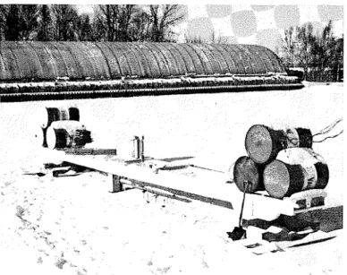
FIG. I. Loading frame at test site.
to a radius approaching infinity, will be small. Results reported by Ramseier (1971 ) for creep tests on snow ice suggest a value for n
of 3. The maximum value of the a to b ratio in the pile tests was 1/3. The displacement rate at b would therefore be 1/9th the displace- ment rate of the pile; or the displacemen't rate u:, measured relative to r = b would have a value of 8/9 of its value if it were measured relative to a position of r approaching infinity. It should be pointed out that this theory assumes that the material (ice or permafrost) is isothermal, isotropic, and homogeneous. Al- though it is very unlikely that a floating ice coves will meet all these assumptions the use of such a theory is justified because of the paucity of experimental data and lack of a more general theory.
Description of Apparatus and Test Site
T h e field program was designed to provide infor- mation o n the rate of pile pull-out under constant load for various load levels a n d ratios of pile diam- eter to ice thickness. A reaction load frame supported by the ice cover and using a lever a r m system with a force multiplication of ten to apply a constant up- ward-acting load was constructed (Fig. 1 ) . T h e 9-m long frame is capable of exerting a force of 3 0 000 N and has a total weight of 1000 kg. ( A n ice thick- ness greater than 200 m m is required for long-term support of this equipment). A shaft supported in low friction bearings transmitted the force from the lever a r m down to a load cell attached t o the pile. All piles were made of B.C. fir turned t o a uniform diameter
on n lathe. A threaded rod through the center of the pile connected it to a coupler o n the bottom of the load cell.
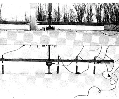
Figure 2 shows the threaded rod, load cell, a n d displacen~ent-measuring cross-arm used during the winter of 1972-73. The cross-arm, made LIP f r o m a 1.5-rn long alunlinum U-section, was fixed at its center to the load cell. Displacement transducers of the D C D T type attached to the cross-arm measured
relative movement between the cross-arm a n d
wooden dowel pins set in the ice. Recording instru-
ments were set u p to provide a continuous record
i.c.rsri.v time of the following: vertical load o n the pile, relative displacements between the cross-arm and the ice cover a t four locations (radii 750, 450, 150, a n d
- 750 m m ) , and ice temperature 150 nlm from the
pile and about 5 0 mrn below the surface plus a i r temperature. Ice thickness was measured periodically and sanlples were recovered to establish the ice type. The experiments were carried o u t over the winters of 1971-72 and 1972-73 on the ice cover of t h e Manoeuvering a n d Rough Water Basin a t the N a - tional Research Council Laboratories in Ottawa. T h i s is an outdoor facility, and it was necessary to w o r k with the ice conditions a n d temperatures that n a t u r e provided. Both winters were characterized b y periods of mild temperatures and rains in January, conditions that caused the ice cover (for the most part granular snow ice) to increase in thickness from about 200 t o 500 m m in a short time. These adverse weather con- ditions restricted the number of tests that could b e conducted.
Test Procedure
A similar test procedure was followed in all cases. A hole with a diameter slightly larger than the pile was augered through the ice cover, and the pile w a s inserted a n d allowed to freeze in. There was n o
C A N . G E O T E C H . J . VOL. 1 I . 1974
/-J
FIG. 2. Cross-arm and load cell in test position.thickening of the ice adjacent to the pile because of the low thermal conductivity of wood. Before starting the test, a hydraulic jack was inserted t o support the lever arm while weights were added to the weight pan. In initiating the test the jack cylinder pressure was gradually released so that there was a smooth ap- plication of load to the pile. F o r each subsequent test the load frame was moved and a new hole prepared for the pile.
Test Results
As there was a general rcfinemcnt of the instrumentation between the first and second winters, it is reasonable to consider the results of each season separately. Applied stress was calculated by dividing the force on the pile by its surface area in contact with the ice.
Winter of 1971-72
Onlv two tcsts on a 50-mm diameter wooden J pile were completed. Vertical movement was measured in relation to a point on the ice 150 mm from the central axis of the pile by a single DCDT. Displacement-time results of the first test, at a stress of 185 kN/m2, are plotted in Fig. 3. (The M's on the abscissa indicate mid- night.) Total ice thickness was 460 mm, com- posed of 150 mm of colunlnar ice overlain by snow ice. It mav be seen that this curve ex- hibits typical creep characteristics, i.e. an initial
instantaneous displacement followed by a period of constant rate displacement and a subsequent accelerating displacement to fail- ure. Pull-out of the pile occurred at 12:OO h
E APPLIED STRESS = 185 kP4/rn2
.
4 --
P I L E DIAMETER = 50 rnrn - Z ICE THICKNESS -- 460 rnrn d/t-
0.109 - - - 2 M M : 0 I I I l I l I I l 0 1 0 2 0 3 0 4 0 5 0 6 0 7 0 8 0 9 0 1 0 0 E L A P S E D TIME, H O U R S FIG. 3 . Test 1-72,after an elapsed time of 44 h. Air temperatures at a location about 1.5 km from the test site are also plotted on Fig. 3 and indicate that the latter part of the test coincided with a general warming trend. O n examining the pile after pull-out, it could be seen that small flakes of ice still adhered to it, suggesting that final failure resulted from a break-down of the ice immediately adjacent to the pile.
FREDERKING: DOWNDRAG LOADS 5 0 - - T H E R M O C O U P L E I N A I R -
. . .
.
. . .
T H E R M O C O U P L E , 7 5 m m B E L O W SURFACE O F I C E-
--
T H E R M O C O U P L E , 3 0 0 m m B E L O W S U R F A C E O F I C E A P P L I E D STRESS = 9 5 k ~ / m ~ P I L E D I A M E T E R = 5 0 m m I C E T H I C K N E S S = 6 1 0 m m d / t = 0 . 0 8 2 E L A P S E D T I M E , H O U R S FIG. 4. Test 2-72.couples were placed in the ice and in the air. The results, at a stress of 9 5 kN/mZ and ice thickness of 610 mm, are shown in Fig. 4. Again, the displacement-time curve shows creep characteristics. Pull-out occurred at 18: 00 h after an elapsed time of 145 h. It may be seen that at about 4 5 h the ice temperature was at the melting point. Although there was an increase in the pull-out rate failure did not occur. Note that between 1 0 and 5 0 h and 9 0 and 115 h, both of which followed cold periods, the creep pull-out rate was zero. The final stage of the test corresponded with a general warming trend. At a few points it ap- pears that there was a decrease in pile dis- placement, possibly due to temperature effects on the load frame and displacement measure- ing apparatus. The following winter these thermal effects wcre investigated.
Winter of 1972-73
Three tests wcre completed on a 100-mm pile. The ice cover comprised 170 m m of columnar-grained ice overlain by snow ice. The force on the pile was continuously mea- sured and was found to be constant over each test period. Relative displacements between the ice cover and the pile were measured with DCDT's at four locations along the cross-arm (Fig. 5 A ) . They were recorded continuously. From these displacement records the movc-
( A ) N O L O A D O N P l L E D C D T P - 0 C R O S S - A R M L O A D C E L L
\(yr"'.
WATER P I L E ( 0 ) P l L E U N D E R L O A Di
- - - I C E/ .
WATER P l L E -FIG. 5 . Schematic of pile and deflection measuring arm.
ment of the pile in relation t o the ice and an approximation of the deflected shape of the ice cover adjacent to the pile were to be deter- mined.
344 C A N . G E O T E C H . J . VOL. l l , 1974
A preliminary test was done to determine thermal effects on the load and deflection mea- suring apparatus. T h e cquipment was sct up as shown in Fig. 5A, with no load on the pile. Load and displacement were recorded over a 3-day period, but n o measurable loads were devcloped on the pile; from the displacement measurcments it was apparent that the cross- arm had tilted and curled to thc extent of several millimeters at the ends as a result of temperaturc changes. O n the basis of these preliminary measurements it was decided to measure pile movcment in rclation to a position 150 mm from the center linc of the pilc where thermal effects on the cross-arm would be at a minimum. Figure 5 B is a schematic of the assumed deflccted shape of the ice when load is applicd to the pilc.
T h c measured deflccted shapc of the ice covcr immediately aftcr load application is shown in Fig. 6 for each of thc threc tests. The circles roprescnt nieasurcd instantaneous dc- flections and thc dashed linc is an approxima- tion of the dcflcctcd shape of tho ice surface in relation to thc cross-arm. Tilting of the cross-arm would cxplain the nonsymmetric deflcctions. Therc is no apparent relation, howevcr, betwcen the deflected shape of the ice and the applicd loads, and thesc attempts at measuring thc deflected shapc of the ice cover were not succcssful.
T h e results of test 1-73, for an applied stress of 120 kN/m2 and an icc thickness of 5 1 0 mm, arc shown in Fig. 7. A 2.5-m square of 25-mm bcad-board insulation was used on the ice to simulate snow cover. From the tem- perature results it may be scen that the insula- tion moderatcd the effects of air tcmperature. The displacement-time curve exhibits creep characteristics. Pull-out occurred at 20:00 h after an elapsed time of 105 h, and as in earlier tests final failure coincided with a warming trend.
Test 2-73, run at a stress levcl of 185 kN/m"n 530-mm ice, is shown in Fig. 8. Pull-out occurred at 1 3 : 0 0 h after an elapsed time of 20 h. N o insulation was used. It is instructive t o relate the results of this test with tcst 1-72, which was done at the same stress level. T h e instantaneous displacements are comparable, as are thc steady-statc displace- ment rates, but there is a major difference in times t o failure.
TEST 2 - 7 3
- 1 . o
P O S I T I O N O N ICE COVER F R O M O F P1LE.m
Frt;. 6. Initial deflected shape of ice cover.
Figurc 9 illustrates the results of test 3-73, done at a stress of 8 0 kN/m%n 570-mm ice. Pull-out occurred at 09:OO 11 after a n elapsed time of 114 h. N o insulation was used. There was a much smaller initial displacement and a ~ l l u c h lowcr steady-statc displacement rate than in test 2-72, which had only a slightly larger applied stress.
Analysis of Results
Figurc 10 is a log-log plot of steady-state creep displace~nent rate versus averagc applied strcss for the pull-out tcsts over both winters. T h e results of each test series werc fitted t o Eq. [6] and the material propcrties derived therefrom arc shown in Table 1.
Given the data, the values of n are in rea- sonable agreemcnt with the stated value of n = 3 for snow ice. Equation [6] suggests that larger diameter piles would have larger stcady-
FREDERKING: DOWNDRAG LOADS E 5 E I I I I I I I I I I I I c 4 - APPLIED STRESS = 120 k ~ / r n ~ - Z PILE DIAMETER = 100 rnrn u ICE THICKNESS = 510 rnrn
2
3 - - u d/t = 0.196 4 a 2 - - rn - 2 M M M M M - a 0 I l l 1 I I I I I I I I 0 1 0 20 3 0 4 0 5 0 6 0 7 0 8 0 9 0 1 0 0 1 1 0 1 2 0 1 3 0 E L A P S E D T I M E , H O U R S FIG. 7. Test 1-73. : 1 0 FIG. 8. Test 2-73. 3 c 5 0 u E 5state creep displacement rates for the same applied stresses, but this has not been the case with wooden piles in ice.
Stehle (1970: see Figure 12) indicates that as the temperature approaches 0 "C the type of material in which the pile is frozen, whether ice, sand slurry, or clay slurry, has little effect on pull-out rate. The steady-state creep dis- placement rate reported by Johnston and Ladanyi (1972) for rod anchors in permafrost
at -3 "C and by Stehle (1970) for W F steel
H-beams in ice at -1 "C are comparable to the steady-state creep displacement rates mea-
I I I I I I I AIR TEMPERATURE
:--<
ICE TEMPERATURE - E ; 4 - Z usured for wooden piles in ice, i.e. in all three studies pile movement is measured in relation to a position on the frozen material that is assumed to be fixed. It seems reasonable to plot the rod anchor results and W F steel H-beam results on thc same figure as the wooden pile rcsults. The steady-state creep dis- placement rates of the W F bcams show an increasing displacement rate with increasing ef- fective diameter, as suggested by Eq. [6]. In general, the dependence of displacement rate on applicd stress is similar for the pile - frozen material configurations considered above.
I I I I I I I APPLIED STRESS = 185 k ~ / r n ~ PILE DIAMETER = 100 rnrn - ICE THICKNESS = 530 rnrn Discussion of Results d/t = 0.189
-
- 2 M - = 0 I I I I I I I _ 0 1 0 2 0 3 0 4 0 5 0 6 0 7 0 8 0 E L A P S E D T I M E , H O U R SA review of the results of two winters of ficld expcriments indicates that under constant load the pull-out of a pile exhibits characteris- tics of creep deformation. Steady-state creep displacement rate is related to applied stress by a power law function. The creep parameter, n, mcasured in these field experiments is com- parable to the value measured in the laboratory for snow ice. Time to pull-out appears to be related to ice temperature as well as to stress level. Time and temperature both influence the pull-out of a pile. Under natural conditions in the field both of these variables are indepen- dent of each other, but combine together to influence the rate of pull-out. To separate the influence of these two variables it is possible that laboratory tests under more controlled
C A N . G E O T E C H . J . VOL. I I . 1974 I C E T E M P E R A T U R E A I R T E M P E R A T U R E 2 - a 0 0 1 0 2 0 3 0 4 0 5 0 6 0 7 0 8 0 9 0 1 0 0 1 1 0 1 2 0 1 3 0 1 4 0 E L A P S E D T I M E , H O U R S I I I I I I I I I A P P L I E D S T R E S S = 8 0 k ~ / m ~ P I L E D I A M E T E R = l O O m m I C E T H I C K N E S S = 5 7 0 m m
-
d / t = 0 . 1 7 5 - - M-
M M M 5 . 6 x 1 0 - 7 m m / r I T I I I I I I I I M I I I FIG. 9. Test 3-73. S T E A D Y S T A T E C R E E P D I S P L A C E M E N T R A T E , m m / rFIG. 10. Steady-state creep displacement rates \~ersrls a p p l i e d stress.
TABLE 1. S u m m a r y o f material property parameters determined f'roni p u l l - o u t tests
~p~ ~ . .. ~ ~~ ~ . ~ ~ ~ . . . ... ... ~ ~- .- M a t e r i a l p r o p e r t y parameters Test series 11 TC f~ 1972 1 . 9 4 5 1 . 3 k N / m 2 3.75 x s - I 1973 3.65 9 3 . 4 k N / m 2 5 . 3 0 ~ 1 0 - ~ s - ' -- - - - .- -- --- - - - - - -
Note: S, = m m / s where i, = f,u/(n - 1).
conditions will have t o be done. These field only pilc diameter effect noted. Thcre was no tests can form a good basis for setting up and clear indication of any pile diameter to ice evaluating relevant laboratory tests. t h i c k n c s ratio on thc pull-out rate of the pile. T h e displacement immediately preceding Results of analogous tests in ice and frozen pull-out was 2-3 mnl for the 50-mm pile and ground indicatc that there was sufficierit simi- about 1 mnl for the 100-m111 pile. This was the larity to justify comparing results, providing
FREDERKING: DOWNDRAG LOADS 347
average temperature of the frozen material was between -1 and 0 "C. The displacement rate for a wooden ~ i l e 1 frozen into an ice cover of mainly snow ice at about - 3 OC under an ap- plied load of 180 kN/m2 is about 1 mm per day. Natural water level fluctuations in a reser- voir are of this order or greater, and it is reasonable to assume that shear stresses de- veloped on wooden piles would be greater than 180 kN/m2.
Further testing is planned for following winters to c x ~ l o r e more fullv the effect of I , varying pile diameters and pile materials. By improving the displacement measuring tech- nique it is hoped that it will be possible to determine the deflected shape of an ice cover. Tests are also planned in which the pile will be moved at a constant rate in relation to the ice.
gratefully acknowledged. Thanks are due also to Gary Mould, Technical Officer, DBR/NRC, for the technical assistance rendered, particu- larly under difficult weather conditions.
This paper is a contribution from the Divi- sion of Building Research, National Research Council of Canada, and is published with the approval of the Director of the Division.
JOHNSTON, G. H., and LADANYI, B. 1972. Field tests of
grouted rod anchors in permafrost. Can. Geotech. J. 9, pp. 176-194.
L O F Q U I ~ T , B. 1951. Lifting force and bearing capacity of an ice sheet. Natl. Res. Counc. Can., Ottawa, Canada. Tech. Trans. TT-164.
PENNER, E . 1970. Frost heave forces in Leda clay. Can. Geotech. J. 7, pp. 8-16.
RAMSEIER, R. 1971. Mechanical properties of snow ice.
Proc. First Int. Conf. Port Ocean Eng. Arct. Cond., Trondheim, Norway, pp. 192-210.
STEHLE, N. S. 1968. McMurdo ice wharf-pullout strength
of piles. U.S. Naval Civ. Eng. Lab., Port Hueneme,
Acknowledgments calif., Tech. Note N-996. -
1970. Holding strength of piles in ice. U.S. Naval
Discussions with and suggestions of various Civ. Eng. Lab., Port Hueneme, Calif., Tech. Rep.