READ THESE TERMS AND CONDITIONS CAREFULLY BEFORE USING THIS WEBSITE. https://nrc-publications.canada.ca/eng/copyright
Vous avez des questions? Nous pouvons vous aider. Pour communiquer directement avec un auteur, consultez la première page de la revue dans laquelle son article a été publié afin de trouver ses coordonnées. Si vous n’arrivez pas à les repérer, communiquez avec nous à [email protected].
Questions? Contact the NRC Publications Archive team at
[email protected]. If you wish to email the authors directly, please see the first page of the publication for their contact information.
NRC Publications Archive
Archives des publications du CNRC
This publication could be one of several versions: author’s original, accepted manuscript or the publisher’s version. / La version de cette publication peut être l’une des suivantes : la version prépublication de l’auteur, la version acceptée du manuscrit ou la version de l’éditeur.
Access and use of this website and the material on it are subject to the Terms and Conditions set forth at
Tracking of design changes for collaborative product development
Xie, H.
https://publications-cnrc.canada.ca/fra/droits
L’accès à ce site Web et l’utilisation de son contenu sont assujettis aux conditions présentées dans le site LISEZ CES CONDITIONS ATTENTIVEMENT AVANT D’UTILISER CE SITE WEB.
NRC Publications Record / Notice d'Archives des publications de CNRC:
https://nrc-publications.canada.ca/eng/view/object/?id=e41cfb54-97af-4404-90a4-55d75c4cbe94 https://publications-cnrc.canada.ca/fra/voir/objet/?id=e41cfb54-97af-4404-90a4-55d75c4cbe94http://irc.nrc-cnrc.gc.ca
T r a c k i n g o f d e s i g n c h a n g e s f o r c o l l a b o r a t i v e
p r o d u c t d e v e l o p m e n t
I M T I - X P - 0 0 8
X i e , H .
A version of this document is published in / Une version de ce document se trouve dans:
Proceedings of the 6th International Conference on CSCW in Design, London, Ontario, July 1, 2001, pp. 175-180
The material in this document is covered by the provisions of the Copyright Act, by Canadian laws, policies, regulations and international agreements. Such provisions serve to identify the information source and, in specific instances, to prohibit reproduction of materials without written permission. For more information visit http://laws.justice.gc.ca/en/showtdm/cs/C-42
Les renseignements dans ce document sont protégés par la Loi sur le droit d'auteur, par les lois, les politiques et les règlements du Canada et des accords internationaux. Ces dispositions permettent d'identifier la source de l'information et, dans certains cas, d'interdire la copie de documents sans permission écrite. Pour obtenir de plus amples renseignements : http://lois.justice.gc.ca/fr/showtdm/cs/C-42
175
Tracking of Design Changes for Collaborative Product Development
Helen Xie
Integrated Manufacturing Technologies Institute
National Research Council of Canada
800 Collip Circle, London, ON, Canada N6G 4X8
[email protected]
Abstract
Market demands are moving manufacturing from mass production to mass customization. To quickly respond to customer needs, product development teams have to work together in a collaborative design environment. This paper presents a product data driven approach to tracking of design changes in a collaborative design environment. In this research, design processes are analyzed to identify product data for tracking design changes. The relationships between product data are established using predecessor-successor, master-subordinate, and geometric constraint relationship types. Forward tracking and backward tracking are designed and implemented to identify impacts of a design change. A prototype system has been implemented to verify the effectiveness of the approach. Finally, a milling machine fixture is used as a design example to show how this approach works. The proposed approach provides a fundamental mechanism to promptly notify other designers of design changes in a collaborative design environment.
1. Introduction
Product development teams today are increasingly facing the challenge of meeting the demands for high product variety and quality while these products are manufactured in relatively low quantities [1]. One of the consequences of the demand for mass customization of products has been the necessity for a team of designers to work together in a collaborative design environment. By exploiting each individual designer’s expertise, the design team can generate design solutions quickly in response to customer requirements. By analyzing conflicts and constraints earlier from different perspectives, the design team is able to achieve design objectives through optimizing product performance, minimizing manufacturing costs, and ensuring that the product can easily and economically be serviced and maintained [2].
Centric to the collaborative design environment are network-supported computer applications. Recently, advanced information technologies, including Internet related technology and distributed object technology, have opened new possibilities for collaborative design. Several frameworks have been proposed for collaborative design systems. SHARE [3] is an open, heterogeneous, network-oriented environment for concurrent product development. It helps a design team to achieve a shared understanding of its designs and design processes using agent-based tools and services. PEDWorks [4] is a prototype system for the web-based collaborative workspace to integrate design activities in a distributed and heterogeneous computing environment. It uses concept of a process-centric collaborative design for engineering designs.
Collaborative design is the process of designing a product through collective and joint efforts undertaken by a team of designers [5]. In a collaborative design process, customer requirements are first captured and product specifications are determined. The information is shared in a database among members of the design team. A system designer decides the rough structure of the system and several design parameters satisfying the given product specification. Then each team member works on a preliminary design for each assembly and a detailed design for each part in a distributed environment. Even though each team member performs its own activities using different disciplines, the design solution may be tightly coupled. Furthermore, the design solution has to satisfy all the design constraints. If there is any constraint violation, design changes become necessary.
One of the issues in collaborative design is that one must assess the impacts of a design change on other design objects and notify other parties promptly [6]. Due to the lack of tracking of design changes in most collaborative design environments, designers have to manually perform a consistency check for a proposed design change to identify all the impacts of the change. As a result, design consistency and accuracy are not guaranteed and design team productivity is compromised. Hence, an effective approach to tracking of design
changes is needed to significantly improve the collaborative design process. Moreover, this approach should be generic so that it can be applied to different products and can be integrated with other application systems.
The focus of this research is to propose an approach to the tracking of design changes in a unified framework [7]. A Web-based collaborative design prototype being proposed allows a team of designers to visualize, manipulate and evaluate the impacts of changes to a design. The remaining sections are organized as follows: Section 2 introduces the approach to the tracking of design changes. Section 3 describes the product information requirements for the tracking of design changes and establishes a change tracking data model. Section 4 introduces a web-based collaborative design prototype and uses an example to demonstrate the efficiency of the approach. Finally, the results of the proposed approach are discussed.
2. Approach to tracking of design changes
A design change is a modification to a product that is necessary to meet the requirements of the product specification, to meet safety standards, or to reduce manufacturing or maintenance costs [8]. From the perspectives of product variation and product improvement, design changes are imperative in collaborative product development processes. Due to the associated relationships between elements in a product, a design change may have an impact on other elements of the product. One of the issues that appears in most of collaborative design systems is the inability to track all the impacts of a design change automatically. Consequently, identifying these impacts usually requires a manual search by designers. This manual process cannot guarantee complete tracking of all design changes. Therefore, automatic tracking of all the impacts of a design change is important in supporting collaborative design environment.
One of the approaches to automatic tracking of design changes is an expert system approach. Design change rules can be stored in a knowledge base so that all the impacts of a design change can be retrieved through an inference engine. However, the rules for automatic tracking of a change are limited to a specific application domain.
Based on product data and the relationships generated during various stages of a product design process, a product data driven approach is proposed to provide a generic mechanism for the tracking of design changes. The product data contains product descriptions for product specification, function decomposition structure, solution principles, layout design, assemblies, and parts. Relationship can be established between two or more
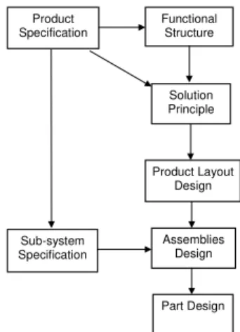
elements of the product description, especially between elements having a predecessor-successor relationship, master-subordinate relationship, or geometric constraint relationship to one another. The predecessor-successor relationship represents the logical dependency developed for product data during the design process (Figure 1). The master-subordinate relationship presents assembly-part hierarchical relationship. The geometric constraint relationship defines fit constraints, contact constraints and consistent constraints between parts. The fit constraint exists if there is a tolerance requirement between parts. The contact constraint represents a physical contact between two parts. The consistent constraint exists if two parts hold a dimensional constraint without a physical contact. With these product data relationships, the tracking of design changes can be achieved.
Product Specification Functional Structure Solution Principle Product Layout Design Sub-system Specification Assemblies Design Part Design
Figure 1. Predecessor-successor relationship. The data driven approach enables designers to identify the total impacts of a proposed design change on an entire product. It provides a fundamental mechanism to promptly notify other designers regarding design changes in a collaborative design environment. This approach supports forward tracking and backward tracking of a design change. Forward tracking identifies the impact of the change on later design stages if a design change occurs at an earlier stage. On the other hand, backward tracking identifies the impacts of changes on previous stages, if a change occurs at a later stage. These operations can be implemented with database support.
The implementation of the data driven approach to tracking of design changes requires that product data and relationships presented above be retrieved from a product database. However, with most of the existing CAD systems, only the product structure, bills of material, and drawings are recorded in the product database. Product data such as product specifications, function structure, solution principles, and design concepts are usually presented in paper documents. Since the automatic
177 tracking of design change is possible only in a computerized environment, product information in a paper document format has to be converted into a product database. Furthermore, neither the logical dependent relationships between design elements nor the logical intermediate processes are documented in practice. Consequently, final design documents are not linked to initial product requirements without human intervention. Thus, the logical dependent relationships among design elements need to be modeled in the product database. To make all the necessary information available for the tracking of a design change, the data driven approach is implemented by extracting necessary product information from design processes and representing the product information in a data model.
3. Data modeling for tracking of design
changes
3.1. Information requirements
Engineering design is the process of devising a system, component, or process to meet desired needs [9]. The design process begins with a product specification and ends up with an artifact. Systematic design methodology [10] suggests a design process through a series of stages including product specification, conceptual design, preliminary layout design, and detailed design. Product specification defines a product’s physical and functional characteristics with precise, measurable details. A product concept is a sketch description of the function structure, solution principle, and the form of product design. The function structure is usually expressed as a hierarchical structure in which a general function is decomposed into a group of sub-functions. A solution principle can be represented as an action principle corresponding to a function. After all solution principles are developed for sub-functions, they are combined to form design concepts. The preliminary layout design is the arrangement of a product structure with bill of materials. The detailed design provides complete dimensions, tolerances, and surface property information for assemblies and parts.
3.2. A change tracking model
The product data driven approach to the tracking of design changes is developed using a data modeling methodology. A data model is a set of concepts that can be used to describe the structure of a database [11]. An entity-relationship model, a popular conceptual modeling method, is used to describe product data with such concepts as entities, attributes, and relationships. The
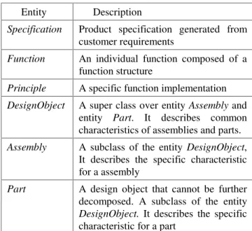
entities and attributes describe an abstract object with its properties. The change tracking model includes following entities: Specification, Function, Principle, DesignObject, Assembly, and Part. The Table 1 summarizes the entities and their descriptions for the change tracking model. The associated attributes are shown in Figure 2.
Table 1. Entities and description. Entity Description
Specification Product specification generated from customer requirements
Function An individual function composed of a function structure
Principle A specific function implementation DesignObject A super class over entity Assembly and
entity Part. It describes common characteristics of assemblies and parts. Assembly A subclass of the entity DesignObject,
It describes the specific characteristic for a assembly
Part A design object that cannot be further decomposed. A subclass of the entity DesignObject. It describes the specific characteristic for a part
The relationships represent a set of associations among entities. They limit the possible combinations of entity instances. Cardinality ratio constraints specify three common combinations for binary relationship types: one-to-one (1:1), one-to-many (1:M), many-to-many (M:N). The relationships in the change tracking model include Requires, Contains, Previous, Solution, Implement, Belongs, and Constraint.
Relationship Requires is a logical dependency relationship between specifications and functions. According to product design principles, a metric in a specification may demand multiple functions, while a function may be constrained by several metrics. Hence, the relationship Requires is of a cardinality ratio of M:N. For instance, clamping force is a metric of a milling fixture specification. It relates several functions including forces accept, forces amplify and forces transmit. On the other hand, fixture alignment to a machine table is a function of a milling fixture. It should satisfy two metrics of the specification, rigid mounting on the machine table and the mounting interface T-slots.
Relationship Contains is a master-subordinate relationship of the function entity that represents the function structure. A function may contain several sub-functions, which is represented as a cardinality ratio of 1:M.
Relationship Previous is a predecessor-successor relationship of the function entity that describes the sequence among the functions in the same level. Since functions are defined in sequence at the same level, a cardinality ratio of 1:1 is used to describe the relationship type Previous.
Relationship Solution is a logical dependency relationship between Function and Principle. In conceptual design, several solution principles are usually proposed for a single function. This suggests that the Solution relationship type is of cardinality ratio 1:N, where N is on the entity Principle side. The proposed principles usually focus on key functions so that part of function instances are related to principle instances. Hence, the participation of Function in the Solution relationship type is partial. In practice, one principle is usually selected for a specific function. Therefore, an attribute of selected is defined in Solution relationship to identify the solution principle that is applied to the product design.
Relationship Implement is a logical dependent relationship between entity Principle and DesignObject. Since a principle may be implemented for several design objects, the relationship Implement is of a cardinality ratio of 1:M, in which entity DesignObject is in the M side.
Relationship Belong is a master-subordinate relationship between different design objects. This
relationship is defined to represent product architecture. Except for an end product, assemblies or parts in any level are dependent of their upper level. According to this relationship, one is able to know the parts or sub-assemblies that an assembly contains.
Relationship Constraint is a geometric constraint relationship between different parts. It describes how a part is associated with other parts through three types of constraints: fitting, contact, and consistency. The constraint type is represented as an attribute of the relationship type. The relationship type Constraint is of cardinality ratio M:N because a part may have interfaces with several parts.
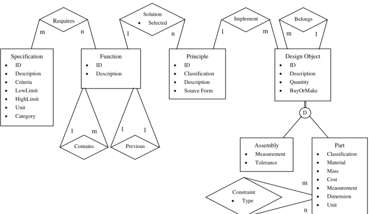
Figure 2 shows the E-R schema diagram for all the entities and relationships discussed above. The model identifies a variety of relationships from specification to assembly and part. In this way, a change which occurs in any point of this chain can be tracked forward and backward to find out its total impact.
The data model can be applied in tracking a design change for any product configuration, because it is based on a general design methodology and independent of any specific design context. It can be used to capture the total impact of a design change by backward and forward searching, no matter at what stage a change occurs.
Specification • ID • Description • Criteria • LowLimit • HighLimit • Unit • Category Function • ID • Description Principle • ID • Classification • Description • Source Form Design Object • ID • Description • Quantity • BuyOrMake Part • Classification • Material • Mass • Cost • Measurement • Dimension • Unit Assembly • Measurement • Tolerance Requires Constraint • Type Solution • Selected 1 m 1 1 m n m n 1 n 1 m m 1 Implement Belongs Previous Contains D
179
4. Implementation and case studies
4.1. Prototype implementation
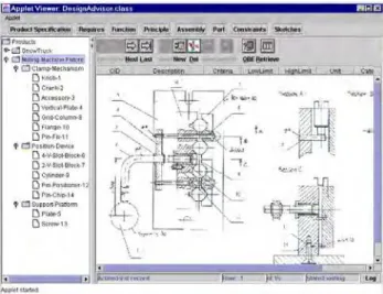
A Web-based software prototype called Design Advisor is designed to verify the proposed approach to tracking of design changes. The Design Advisor allows a design team to share product information from a back-end database through a Web server. Java Applet is chosen for the client-side user interface (Figure 3). It provides an enhanced functionality to display a product structure tree at different levels. It also provides designers the ability to manipulate the product database. JDBC API is used to access the database. From the user interface, a designer is able to switch to different design views using the buttons on the toolbars. The Product Specification, Function, Principle, Assembly, and Part views provide designers with the capability to enter, modify, browse, and search product data in a database. These views also help in linking product data for predecessor-successor relationships. The Requires view allows the designers to establish many-to-many type of relationships between specification and function. The Constraint view allows designers to specify geometric constraints, another many-to-many type, among parts. The Sketch view provides designers abilities to review engineering drawings.
4.2. A design case
The design case for a milling machine fixture [12] was studied to obtain its product information from the design process. The design process for the fixture includes product specification, function structure, solution principle, assembly design, and part design. The product specifications are classified as functions, conditions of the technical processes, operation properties, ergonomic properties, appearance, distribution properties, delivery properties, manufacturing properties, and cost. According to the design specifications, functions of the fixture are proposed and decomposed into functions. These sub-functions can be implemented using available solution principles. For each primary sub-function, there are several solution principles available. Only one solution for each primary sub-function is selected for implementation. The layout design can be finalized based on synthesis of these solutions.
The layout design for the fixture is shown in Figure 3. The fixture is designed as three assemblies. The clamp mechanism consists of knob, crank, accessory, vertical plate, grid column, flange, and pin fix. The position device consists of 4-V-slot block, 2-V-slot block, cylinder, pin positioner, and pin chip. The support platform consists of plate and screw. The relationships
between the solution principles and parts are identified. A solution principle may require several parts to perform a function. For example, the principle two-column guidance is related to the vertical plate, 4-V-slot block, 2-V-slot block, and grid column. The constraint relationships among parts are also identified in terms of fitting, contact, and consistency.
Figure 3. The fixture layout design.
The product information for tracking of design changes involves product specifications, functions, principles and design objects. The predecessor-successor, master-subordinate, geometric constraint relationships among them provide a mechanism to search for all possible impacts of a design change on the product. The tasks for searching for all possible changes are classified into two types based on search directions: forward tracking and backward tracking. The generating sequence of product data is from specification, function, principle, to design object. Forward tracking identifies the impact when a change occurs in upstream. It is applicable for customized product design, variant design and design improvement. Backward tracking identifies the upstream impacts when a change occurs in a part design. It is used for improving manufacturability and maintainability.
For forward tracking, a change appearing in specifications represents the most complex case because the impacts are distributed in functions, principles, and design objects. An example is given to demonstrate how the impacted changes are tracked using the approach.
Suppose a clamping force in the specification has to be changed to meet a customer’s requirement, all the impacted items in parts should be located. The query operations are used to select records from individual tables and to combine related records from several tables for a retrieval request. The forward search query can be represented in SQL statement. SELECT section represents related attributes that are to be included in the
query result. These attributes consist of ObjectID and RelatedObjectID. FROM section represents the tables involved and their associated relationships. WHERE section specifies the criteria for the query.
The results of this query are shown in Figure 4. The Clamp force is related to function Force Accept and Force Amplify. The function Force Accept is implemented by principle Handle with X-axis rotation. The function Force Amplify is implemented by principle Screw/Nut. The principle of Handle with X-axis rotation corresponds to Knob and Crank. The principle of Screw/Nut corresponds to Cylinder and Flange-. The Knob, Crank, Cylinder, and Flange- are constrained by Accessory, Vertical plate, 4-V-slot-Block, and Pin-fix. Hence, If the clamp force is to be changed, Knob, Crank, Accessory, Vertical plate, 4-V-slot-block, Cylinder, Flange-, and Pin-fix should be changed too. By reviewing the description of functions, principles, and design objects, the results are found to be reasonable.
Figure 4. Impact of changes in forward tracking. Backward tracking is used for searching the impact of changes for parts, principle, function, and specification when a change occurs in a part. For example, the vertical plate needs to be changed to improve manufacturability. Impact of all changes can be searched using a SQL statement. The vertical plate holds a crank and column and is positioned by an accessory. Hence, a change in the vertical plate may result in changes to crank, accessory, and column. These parts implement a solution principle “two column”. The principle “two column” performs a function “clamping surface guide”. The function corresponds to a metric in specification “clamping of pin for milling”. Therefore, changing a vertical plate may result in a change in “clamping of pin for milling”.
From the above two examples, it is concluded that the change tracking model can be used effectively for the two types of design change tracking. The query results are found to be reasonable.
5. Conclusions
The analysis of product design processes is important for determining the product data involved in design changes. In this paper, the product data driven approach is proposed to address design change issues in collaborative design environment. The core of the approach is the change tracking model, which represents product data and their relationships in specification, function, principle, design object, assembly, and part. The approach can be used for generic product development because the change tracking model is based on abstract product information and is independent of any specific design context. Although the current model is suitable for tracking changes during the product design process, it can be extended to the product life cycle also.
6. References
[1] U. Roy and S. S. Kodkani, Product modeling within the framework of the World Wide Web, IIE Transactions, 31/7, pp.667-677, 1999.
[2] J. Hartley, Concurrent Engineering, Cambridge, Mass., Productivity Press, 1992.
[3] G. Toye, M. Cutkosky, L. Leifer, J. Tenenbaum and J. Glicksman, SHARE: A Methodology and Environment for Collaborative Product Development, Proceedings of 2nd
Workshop on Enabling Technologies: Infrastructure for Collaborative Enterprises, pp. 33-47, 1993.
[4] H. Kim, J. Y. Lee, and S. Han, Process-centric Distributed Collaborative Design based on the Web, Proceedings of
DECT’99: 1999 ASME Computers in Engineering Conference,
pp.1-9, 1999.
[5] W. Shen, Web-based Infrastructure for Collaborative product Design: an Overview, Proceedings of the fifth
International Conference on Computer Supported Cooperative Work in Design, pp. 239-244, 2000.
[6] L. Wang, W. Shen, H. Xie, J. Neelamkavil, and A. Pardasani, Collaborative Conceptual Design: a State-of-the-art Survey, Proceedings of the fifth International Conference on
Computer Supported Cooperative Work in Design, pp. 204-209,
2000.
[7] H. Xie, Effective Configuration Management for
Supporting Product Development Process, Master’s Thesis, The
Department of Mechanical Engineering. The University of Saskatchewan, 1998.
[8] R. E. Monahan, Engineering Documentation Control
Practices and Procedures, New York, Marcel Dekker, Inc.,
1995.
[9] A. Ertas and J. C. Jones, The Engineering Design Process, New York, John Wiley & Sons, 1993.
[10] V. Hubka, Principles of Engineering Design, London, Butterworths, 1982.
[11] R. Elmasri and S. B. Navather, Fundamentals of Database
Systems, New York, The Benjamin/Cummings Publishing
Company Inc., 1989.
[12] V. Hubka, M. M. Andreason, and W. E. Eder, Practical
Studies in Systematic Design, London, Butterworths, pp. 22-37,