Publisher’s version / Version de l'éditeur:
ASHRAE Transactions, 78, 1, pp. 192-198, 1972
READ THESE TERMS AND CONDITIONS CAREFULLY BEFORE USING THIS WEBSITE. https://nrc-publications.canada.ca/eng/copyright
Vous avez des questions? Nous pouvons vous aider. Pour communiquer directement avec un auteur, consultez la première page de la revue dans laquelle son article a été publié afin de trouver ses coordonnées. Si vous n’arrivez pas à les repérer, communiquez avec nous à PublicationsArchive-ArchivesPublications@nrc-cnrc.gc.ca.
Questions? Contact the NRC Publications Archive team at
PublicationsArchive-ArchivesPublications@nrc-cnrc.gc.ca. If you wish to email the authors directly, please see the first page of the publication for their contact information.
NRC Publications Archive
Archives des publications du CNRC
This publication could be one of several versions: author’s original, accepted manuscript or the publisher’s version. / La version de cette publication peut être l’une des suivantes : la version prépublication de l’auteur, la version acceptée du manuscrit ou la version de l’éditeur.
Access and use of this website and the material on it are subject to the Terms and Conditions set forth at
Thermal performance of exterior steel-stud frame walls
Sasaki, J. R.
https://publications-cnrc.canada.ca/fra/droits
L’accès à ce site Web et l’utilisation de son contenu sont assujettis aux conditions présentées dans le site LISEZ CES CONDITIONS ATTENTIVEMENT AVANT D’UTILISER CE SITE WEB.
NRC Publications Record / Notice d'Archives des publications de CNRC:
https://nrc-publications.canada.ca/eng/view/object/?id=f464e35d-c69b-448a-9518-e17c30978f5a
https://publications-cnrc.canada.ca/fra/voir/objet/?id=f464e35d-c69b-448a-9518-e17c30978f5a
Ser
TH1
N21r2
no.
596
c . 2BLDG
Jb?r(
.I" b"? f EL-AN
A&'.
-
NATIONAL RESEARCH COUNCIL OF CANADA
CONSEIL NATIONAL DE RECHERCHES D U CANADA
Thermal Performance of Exterior
Steel-Stud Frame Wal Is
by J.R. Sasaki
Reprinted from ASH RAE Transactions
Vol. 78, Part I, 1972 p. 192 - 198
By Permission of the American Society of Heating, Refrigerating and Air-Conditioning Engineers, I nc.
Research Paper No. 596 of the
Division of Building Research
RENDEMENT THERMIQUE DES PANS EXTERIEURS CONSTITUES
DE MONTANTS EN AClER
II est difficile, avec les methodes de calcul existantes, de dkterminer avec precision le rendement thermique, par temps froid, des pans constituks de montants de haute conductivite. C'est pourquoi on a fait des experiences en laboratoire avec un certain nombre de pans 2 montants en acier; on a dktermini la resistance thermique totale et la caractCristique de la tempCra- ture de la surface intkrieure, qui indiquent le potentiel de condensation et de marques de poussisre. L'Cpaisseur du rev6te- ment exterieur et de I'isolant et la position de I'isolant dans I'espace des montants ont kt6 soumises 2 des variations afin de dCterminer leur effet sur le rendement. On a compark le rendement des murs en acier, determine au moyen d'experiences, 'avec le rendement calculk.
No. 2226
J. R. Sasaki
THERMAL PERFORMANCE OF EXTERIOR
STEEL-STUD FRAME WALLS
Steel studs have been used quite successfully in the con- struction of interior partitions and are now being offered as an alternative t o wood studs in exterior frame wall con- struction. In addition t o its structural performance, the major consideration in the acceptance of an exterior steel frame wall for use in cold-weather regions is its thermal performance. As it was questionable whether existing cal- culation methods could predict the thermal performance of this type of wall, a laboratory investigation was undertaken t o define the performance of steel frame walls and t o de- termine the effect of some of the design features o n their thermal performance. The results of the investigation were also used t o check whether the calculation method outlined in ASHRAE HANDBOOK O F FUNDAMENTALS of the American S o ;iety of Heating, Refrigerating and Air-Con- ditioning Engineers1 was adequate for evaluating walls that have high-conductance framing members bridging a layer of air-permeable insulation, and that experience convective h e ~ t exchange between the framing members and the air in the insulated stud space.
The cold-weather performance of an exterior wall is expressed by its over-all thermal resistance and inside sur- face-temperature character is ti^.^>^,^ The surface tempera- ture characteristic determines the condensation potential and the dust-marking potential of the wall.
Objectionable condensation occurs o n the inside sur- face of a wall whenever the surface temperature drops below the dew point temperature of the adjacent air; the minimum inside surface temperature (tmi,) is, therefore, the upper limit for dew point temperature if condensation is t o be avoided.
Differential dust marking is caused by sharp surface temperature gradients and by a large ten~perature difference between the surface and adjacent air.5 The rate of dust deposition depends o n the temperature difference between surface and air; dust patterns become more noticeable as surface temperature gradients increase. The dust-marking potential of frame walls can, therefore, be represented by the inside surface temperature over the stud ( t S t u d ) , the
J. R . Sasaki is research officer, Building Services Section, Division of Building Research, National Research Council of Canada, Ottawa, Ontario, Canada. This paper was prepared for presentation at the ASHRAE Semiannual Meeting, New Orleans, La., January 23-27,
19 72.
horizontal surface temperature gradient caused by the stud (At,,), and the surface temperature depression caused by the fasteners holding the interior wall panel t o the studs (Atscrew).
The minimum acceptable standards of heat-transmis- sion performance and condensation performance of a wall can be specified without any difficulty. Unfortunately, the minimum standard of dust-marking performance cannot be specified as easily because dust marking depends n o t only on the surface temperature gradients but also o n the sever- ity and duration of the cold weather experienced, the clean- liness of the inside air, and the frequency of cleaning and redecoration. F o r example, exterior walls of conference rooms and living rooms, where tobacco smoke concentra- tion is high, should have a higher performance rating than walls intended for classrooms or bedrooms, which have cleaner air. There is a t present n o quantitative information correlating the incidence of dust marking with wall surface temperature performance and the foregoing factors. In the absence of such information, the dust-marking performance of steel frame walls can only be judged by comparison with the performance of wood frame walls, which have proved to be reasonably acceptable in practice.
GENERALITIES ON FRAME WALL PERFORMANCE
Frame walls are characterized by an air space formed by the studs, inside wallboard and outside sheathing board. The air space may be partially or fully insulated, or may n o t be insulated a t all. The frame walls discussed in this paper are either partially or completely filled with a blanket of air- permeable glass fiber insulation. The thermal performance of such walls is controlled by the studs which thermally bridge the insulation layer;6 the thermal resistance of the insulation and wallboards; the convective air flow through the i n ~ u l a t i o n ; ~ and the convective heat exchange between the studs and the air in the stud space.
Studs that bridge the insulation layer reduce the over- all resistance of a wall and create large surface temperature differences o n the inside wall surface. The bridging effect of wood studs is less than that of steel studs because of the lower conductivity of wood. T h e bridging effect of steel studs can be reduced by introducing a high-resistance element (thermal break) between the stud and wallboards, increasing the heat-flow path length between the cold and
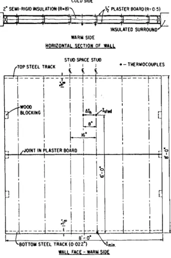
COLD SlDE
WARY SlDE WORlZOMlAL SECTION OF WALL
WALL FACE - WARY SIOL
Fig. I . Steel-stud wall co~zfigtration
"7
r
! k Y : A ~ s s = O . ~ m'ti
Yi
F;+
lr/
0.042g--(
A3
WELD ,
EXPANDED CHANNEL
Fig. 2. Details of steel studs
OPEN-WEB (WELDED RODS)
warm faces o f the stud, and reducing the cross-sectional area of t h e stud web.
T h e thermal resistance of t h e stud-space insulation and the inner and o u t e r wallboards have a large effect o n the thennal performance of frame walls, since these elements are the greatest contributors t o the over-all resistance o f a wall. Maximum resistance is achieved when the s t u d space is completely filled with insulation. Complete filling m a y , however, exaggerate t h e surface temperature depression caused b y the studs and thereby increase the inside surface temperature gradients. Low conductivity wallboards o n the inside and outside will increase t h e over-all resistance a n d also reduce the inside surface temperature gradients.
When the s t u d space in a frame wall is only partially filled with insulation, the location of t h e insulation layer relative t o the inner a n d outer wallboards affects the sur- face temperature performance. Inside surface temperature gradients are smallest when the insulation is against the o u t e r sheathing, since this location exposes part of the stud web t o convective h e a t exchange with warm air in the stud space.
Convective air flow through and around the insulation layer is another i m p o r t a n t factor t h a t can degrade the thennal performance of a wall when the stud space is only partially filled. This effect can be minimized by placing the insulation tightly against the inner o r o u t e r wallboard.
LABORATORY INVESTIGATION
Five steel-stud frame walls were constructed as shown in Fig. 1 ; s t u d details are shown in Fig. 2. Plaster facing boards were attached t o the studs by steel screws. A 2-in. by 4-in. wood-stud frame wall having t h e same configuration was also constructed. T h e effect of the exterior finish was neg- lected in t h e walls investigated.
LIGHT CHANMEL
LIGHT CHANNEL (LOUVREDI
THICKNESS
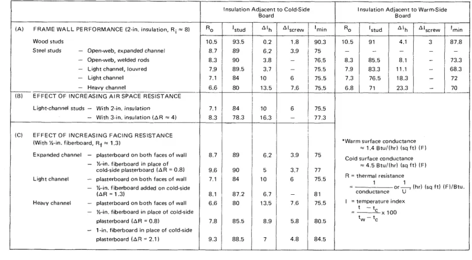
TABLE I - Thermal Performance of Wood and Steel Frame Walls*
I I I
( A ) F R A M E W A L L PERFORMANCE (2-in. insulation, R i = 8 ) Wood studs
Steel studs - Open-web, expanded channel
- Open-web, welded rods
- L i g h t channel, louvred
- Light channel
- Heavy channel
E F F E C T O F I N C R E A S I N G A I R SPACE RESISTANCE
I
Insulation Adjacent t o Cold-SideI
Insulation Adjacent t o Warm-Side Board BoardLight-channel studs - W i t h 2-in. insulation 7.1 8 4
- With 3-in. insulation ( A R = 4)
-
8.3 78.3 16.3 (C) E F F E C T OF I N C R E A S I N G F A C I N G RESISTANCE( W i t h %in. fiberboard, R f = 1.3)
Expanded channel - plasterboard o n b o t h faces o f wall 8.7
- %-in. fiberboard i n place o f
cold-side plasterboard ( A R = 0.8) 9.6 Light channel - plasterboard o n b o t h faces o f wall 7.1
- %-in. fiberboard added on cold-side
( A R = 1.3) 8.1 Heavy channel - plasterboard o n b o t h faces o f wall 6.6
- %in. fiberboard i n place of cold-side plasterboard ( A R = 0.8) 7.8
-
1 -in. fiberboard i n place of cold-side plasterboard ( A R = 2.1 ) 9.3'Warm surface conductance
= 1.4 B t u / ( h r ) (sq f t ) ( F ) Cold surface conductance
= 4.5 B t u l ( h r l (sq f t ) ( F ) R = thermal resistance I - o r 4 ( h r ) (sq f t ) ( F ) / B t u . conductance U I =temperature index
The walls were evaluated in the DBR/NRC wall-panel testing unit8 with nominal air temperatures o n the warm and cold sides of 70 F and - 2 0 F , respectively. The surface
conductance values at the warm and cold faces of the wall were approximately 1.4 and 4.5 Btu/(hr) (sq ft) ( F ) , re- spectively.
T h e inside surface temperature over the stud centerline ( t S t u d ) and the horizontal surface-temperature difference between stud centerline and stud-space centerline ( 4 t h ) were measured approximately 6 f t above the wall base. The minimum inside surface temperature ( t m i n ) was measured at the intersection of the stud and the bottom track but away from any attachment screws. The additional surface temperature depression caused by the steel, attachment screws (At,,,,,) was measured for some of the walls.
The thermal performance of the walls was determined with 2-in. semi-rigid insulation against the cold-side sheath- ing board, and again with the insulation against the interior finish. T h e performance of the light-channel wall was also determined 'with 3 in. of the same insulation, which effec- tively filled the space between the studs. Additional tests were performed o n some of the walls using cold-side sheath- ing boards having a higher thermal resistance than the standard plasterboard.
T h e over-all thermal resistance, R,, and the surface temperature characteristic of the walls are listed in Table I. The inside surface temperature characteristics are expressed in terms of a temperature index, I, defined as:
where t, and t, are the warm and cold side air tempera- tures, respectively. Thus, the terms, I s t u d , A l h , AIscrew and l m i n are the non-dimensional equivalents of the inside surface temperatures, t S t u d , A t h , At,,,,, and t m i n , respec- tively.
Surface temperatures and temperature differences for particular warm- and cold-air conditions can be calculated using the tabulated values of temperature indices and the foregoing equation, as shown in the following example.
T h e values of I s t u d and AIh for the light- channel steel wall with insulation t o cold side, are listed as 8 4 and 10, respectively. F o r an inside air temperature of 7 0 F and an outside air temperature of 10 F , the values of tStud and Ath would be:
(70 - 10)
Ath( l o F) = Alh X - = 6 F deg. 1 0 0
Wood Frame Wall Performance
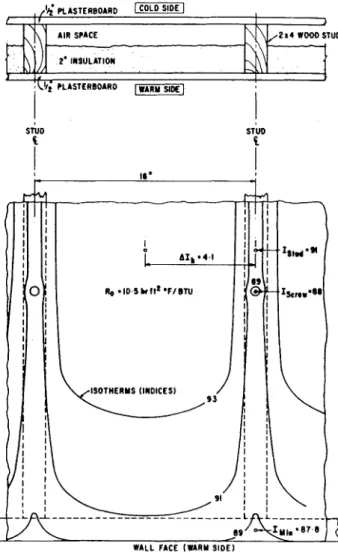
The surface temperature performance of the wood frame wall was better when the insulation was t o the cold side rather than the warm side. T h e latter configuration, how- ever, is the usual method of installation with paperbacked insulation. T h e inside surface temperature characteristic of this wall is shown in Fig. 3. T h e overall resistance of the wall was 10.5 (hr) (sq ft) (F)/Btu. T h e inside surface tem- perature index over the stud ( I s t u d ) was 9 1 ; the horizontal
, /(E; PLASTERBOARD I 1 ,
i
'\$; PLASTERBOAR0 DE]-SIi
Fig. 3. hlside surface ternperatctre characteristic (indices) - wood frame wall
surface temperature index difference ( A I h ) caused by the stud was 4.1 ; the surface temperature index over the attach- ment screw (I,,,,,) was 8 8 (Istud - AIscrew); and the
minimum inside surface temperature index ( I m i n ) was 87.8. This is the thermal performance standard against which the steel frame walls were compared.
Steel Frame Wall Performance
T h e walls with the open-web studs had significantly higher resistance values than the solid-stud walls; and the inside surface-temperature characteristics of the walls with the open-web studs were closer t o the characteristics of the wood wall. This is apparent in Fig. 4 where the horizontal surface-temperature profiles of the open-web (welded rod) stud wall and the heavy-channel stud wall are compared with that of the wood wall.
T h e steel screws used t o fasten t h e inside wallboard t o the studs caused a local depression in the inside wall surface temperature. This temperature depression, AI,,,,,, was linearly dependent on AIh, as shown in Fig. 5. The screw temperature difference must be added t o AIh t o indicate the maximum horizontal temperature difference that would occur o n the inside surface of a wall, and subtracted from I m i n t o indicate the lowest wall surface temperature.
T h e over-all resistance of the steel walls was relatively unaffected by the location of the insulation in the stud
'Warm surface conductance = 1.4 Btul(hr) (sq f t ) (F) Cold surface conductance = 4.5 Btul(hrl (sq f t ) (F)
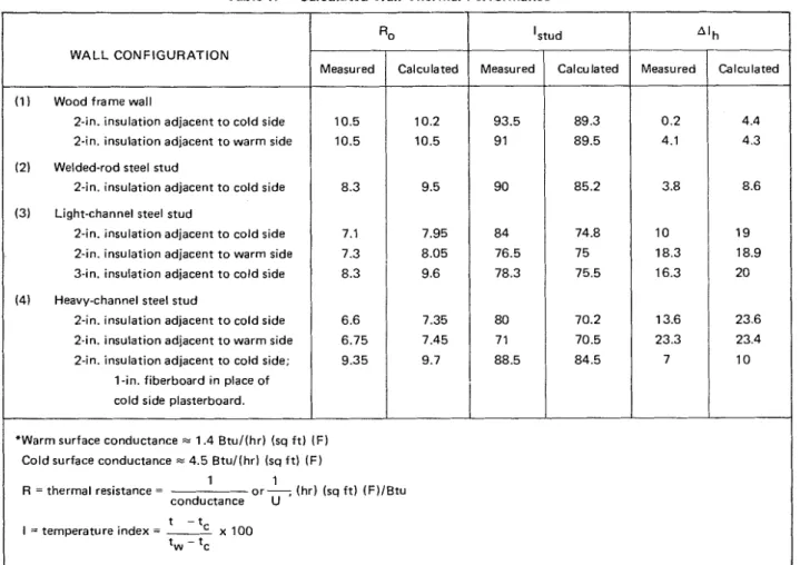
Table I I
-
Calculated Wall Thermal Performance*1 1
R = thermal resistance = o r 7 (hr) (sq f t ) (F)/Btu
conductance U t - t I = temperature index =
2
x 100 t~ - t~ WALL CONFIGURATION 1 Woodframewall2-in. insulation adjacent to cold side 2-in. insulation adjacent to warm side (2) Welded-rod steel stud
2-in. insulation adjacent to cold side (3) Light-channel steel stud
2-in. insulation adjacent to cold side 2-in. insulation adjacent to warm side 3-in. insulation adiacent to cold side (4) Heavy-channel steel stud
2-in. insulation adjacent t o cold side 2-in. insulation adjacent to warm side 2-in. insulation adjacent to cold side;
1-in. fiberboard in place of cold side plasterboard.
Measured Calculated
+
'stud
space, b u t the surface temperature differences were greater and the minimum wall temperature lower when the insula- tion was towards the inside rather than the outside. F o r example, AIh for the heavy-channel wall increased by 9.8 and I m i n dropped by 5.5 when the insulation was moved from the cold side t o the warm side.
The thermal resistance of the steel frame walls was improved by increasing the thickness of insulation in the stud space and by increasing the thermal resistance on the inner and outer faces of the wall. Increasing the thickness of the stud-space insulation in the light-channel wall from 2 in. t o 3 in. increased the over-all resistance of the wall by 1.2 units. This increase in resistance was accompanied, how- ever, by an increase in AIh of 6.3.
A better method for increasing the over-all wall re- sistance was t o add high-resistance material on the face of the wall. Replacing the plasterboard on t h e cold side of the heavy-channel wall with I-in. fiberboard increased the over-all resistance by 2.7 units and reduced AIh by 6.5. The surface temperature profile of the heavy-channel wal: with this high-resistance sheathing'is shown in Fig. 4.
Although the minimum surface temperatures measured on the steel walls were considerably lower than those measured on the wood walls, none of the walls appeared t o have a minimum value so low as t o cause inside surface condensation problems under normal conditions of use.
Measured 93.5 9 1 90 84 76.5 78.3 80 71 88.5 Ro
For example, the heavy channel wall with R 7 insulation t o the warm side had a minimum index of, I m i n = 70. Fig. 5 indicated a further screw index depression of approximately AISc,,, = 12 for this wall. A screw located a t the intersection of the bottom track and a stud would, therefore, have a temperature index of 5 8 , which is lower than that of any other wall. For outdoor and indoor air tem- perature of 0 F and 72 F, respectively, the minimum screw temperature would be 4 2 F ; condensation would not occur on the screw until the inside relative humidity exceeded approximately 35%. Calculated 89.3 89.5 85.2 74.8 75 75.5 70.2 70.5 84.5 Measured 10.5 10.5 8.3 7.1 7.3 8.3 6.6 6.75 9.35
Calculated Thermal Performance
As a primary purpose of the study was t o determine whether the thermal performance of frame walls could be evaluated without testing, the over-all resistances and inside surface temperatures of a number of the simpler frame wall configurations were calculated using the "zone" method described in the 1967 ASHRAE HANDBOOK O F FUNDA- MENTALS (Chapter 26, page 421). The calculated and measured values are compared in Table 11. The calculated resistance values were just slightly lower lhan the measured Calculated 10.2 10.5 9.5 7.95 8.05 9.6 7.35 7.45 9.7
values for the wood frame walls, but were 4 t o 15% higher than the measured values f o r the steel walls. This is n o t too surprising considering the zone method does not account for convective heat transfer in the stud space or convective air exchange through the insulation. T h e calculated values
of AI,, were close t o the measured values for only those
walls with insulation towards the warm side; the agreement was poor f o r all the other walls.
S U M M A R Y
High-resistance steel studs used in frame wall construction can provide thermal performance comparable t o that of wood frame walls. Lower-resistance steel studs can provide comparable performance if some of the following sugges- tions are incorporated in the wall design:
(1) Use stud-space insulation having a thickness less than the depth of the stud, and place i t against the cold-side sheathing board.
(2) Use material with a high thermal resistance for the cold-side sheathing and the interior finish.
( 3 ) Place a high-resistance spacer between the stud and the outer and/or inner wallboards, or between the exterior wallboard and exterior cladding material.
[rnl
, W000 WALL
,
,WELDED-ROD STEEL WALL II 1 , ; P C A J C E R B o r R O f l ~ ~ m i ~ ~ ' I
j
V l l T V D
I
I STUD C Ci
C-
loorI
I
I 1
I
; &. 0.3 ~ I I ~ T I O T U I*. 76,s --HEAVY-CHAWEL STEEL WAU Y W I F E D HEAVY-CHAWIEL STEEL UU
Fig. 4. Horizontal temperature profiles o n inside surface of four walls (indices)
Fig. 5. Dependence of screw temperature depression on stud tem- perature difference
The need for care in placing stud-space insulation tightly against a wallboard and against the studs must be emphasized. Lips on the flanges of the steel studs tended t o create air voids o n both sides of the insulation near the studs that permitted convective air flow through the insula- tion. Improperly located thermal separators between the studs and wallboards would also create similar voids and air circulation. Thus, the possible reduction in the thermal effectiveness of the insulation must be recognized when friction-fit insulation without paper backing is used in steel frame walls.
The current study indicates that the ASHRAE "zone" method of calculation is capable of estimating the over-all resistance of steel frame walls reasonably well, but is in- capable of estimating the inside surface temperature per- formance with any reliability.
REFERENCES
1. ASHRAE HANDBOOK
or:
FUNDAMENTALS, 1967, p. 421. 2. G. 0. Handegord and N. B. Hutcheon, Thermal Performance ofFrame Walls, ASH&VE TRANSACTION, Vol. 5 8 , 1952, p. 171. 3. G. 0 . Handegord and N. U. Hutcheon, Thermal Performance of Frame Walls, Part 11, ASH&VE TRANSACTIONS, Vol. 59, 1953, p. 449.
4. G. 0. Handegord, Thermal Performance of Frame Walls, Part 111, ASHRAE JOURNAL, Heating, Piping and Air Conditioning, June 1957, p. 145.
5. R. A. Nielsen, Dirt Patterns o n Walls, ASH&VE TRANS- ACTIONS, Vol. 46, 1940, p. 247.
6. W. P. Brown and A. G. Wilson, Thermal Bridges in Buildings, Canadian Building Digest No. 44, 1963, Division of Building Research, National Research Council of Canada.
7. S. Wolf, K. R. Solvason and A. G. Wilson, Convection Air Flow Effects with Mineral Wool Insulation in Wood Frame Walls, ASHRAE TRANSACTIONS, Vol. 72, Part 11, 1966, p. 111.3.1. 8. K. R. Solvason, Large-scale Wall Heat-flow Measuring Apparatus,
DISCUSSION
CHARLES F. GILBO (Armstrong Cork Co., Lancaster, Pa.): We verified y o u r studies very closely in a mobile h o m e study. In t h e mobile home industry some manufacturers are contemplating going t o metal frames and we have been interested in the thermal properties of these units. The vari- ations t h a t y o u have noticed in t h e thermal pattern a t the stud locations have t o d o primarily with internal convection within t h e walls. If y o u take ASHRAE GUIDE AND DATA BOOK data and consider it only for those cases that d o not have internal convection, t h e computed check is very g o o d , but if y o u d o have a wall construction t h a t has a high internal convection factor, then t h e check is very poor.
MR. SASAKI: 1 agree. T h e zone method being only a con- vective arithmetic method does not account for convective heat exchange within t h e wall spaces.
MR. GILBO: Your Fig. 3 was most interesting because that really did show the effect of t h e convection within the stud space. The differences in surface temperature were coming primarily from t h e segregation and lamination of t h e air within t h e space.
ALEX MERRILL (Peoples Gas Co., Chicago, Ill.): You didn't make any comment o n dust marking. I wondered if y o u concluded any.
MR. SASAKI: As I indicated in m y opening remarks, there are many factors t h a t affect dust marking. We only looked at t h e surface temperature aspect of t h e problem. Factors such as t h e cleanliness of t h e r o o m air, t h e duration and severity of t h e cold weather conditions, o r t h e frequency of cleaning of t h e walls, were n o t studied. I should report t h a t ,
subsequent t o t h e laboratory study, I examined a number of high-rise apartment buildings that had steel-stud walls. Some of these buildings had been LIP for three o r four years, but I didn't notice, with the exception of one build- ing, a n y dust marking associated with t h e steel studs that was severe enough t o be noticeable. In o n e suite of one apartment building I did see dust marking over the studs, but n o t enough t o be objectionable. A more common prob- lern was dust marking over the baseboard convectors.
JOHN I. YELLOTT (Yellott Solar Energy Labs, Phoenix, Ariz.): Why does t h e dust go t o the cold instead of t h e warm parts of t h e wall?
MR. SASAKI: According t o Nielson, dust marking is a thermal phenomenon, ~ ~ n r e l a t e d t o humidity conditions or t o air permeability of the wall. T h e ~nolecular activity of t h e air propels dust particles against t h e wall in the direc- tion o f t h e air temperature gradient. Dust deposition is greatest where t h e temperature difference between t h e air and surface is greatest; t h a t is, at t h e coldest surfaces.
MR. YELLOTT: I have Listened with t h e greatest of interest to these t w o previous papers and I would like t o commend t h e authors o n t h e truly elegant approach t o two very difficult problems. I think that t h e dust marking effect had t h e name Blacktin Effect. Some 30 years ago, when I was a t t h e Institute of Gas Technology in Chicago, we were trying t o find ways t o improve dust collection and I came upon that name. I think I can find t h e reference for you. It was t h e Royal Society of London; a n obscure paper b y an obscure physicist. Now it is nothing like as obscure because it has become a real problem, as we have just heard.
This publication is being distributed by the Division o f Building Research of the National Research Coun- cil of Canada. It should not be reproduced in whole or in part without permission of the original pub- lisher. The Division would be glad to be of assistance in obtaining such permission.
Publications of the Division may be obtained by mailing the appropriate remittance (a Bank, Express, or Post Office Money Order, or a cheque, made payable t o the Receiver General of Canada, credit NRC) to the National Research Council of Canada, Ottawa. K I A OR6. Stamps are not acceptable.
A list of all publications of the Division is available and may- be obtained from the Publications Section, Division of Building Research, National Research Council of Canada, Ottawa. K I A 0R6.