COMPRESSIVE BEHAVIOR OF REFRACTORY CERAMICS
AT ELEVATED TEMPERATURES
by
Fouad George Tamer Bachelor of Engineering American University of Beirut
(1983)
Master of Science
Massachusetts Institute of Technology (1985)
SUBMITTED TO THE DEPARTMENT OF CIVIL ENGINEERING IN PARTIAL FULFILLMENT OF THE
REQUIREMENTS FOR THE DEGREE OF DOCTOR OF PHILOSOPHY
at the
MASSACHUSETTS INSTITUTE OF TECHNOLOGY
October 1988 Copyright e 1988 M.I.T
Signature of Author
Department of Civil Engineering October 25, 1988
? i
Certified by Prossor OreBuyukozturk Thesis Supervisor Accepted by Chairman, DepartmentalProfessor Ole S. Madsen
Professor Ole S. Madsen
Committee on Graduatem, gr wTz
APR'
27
1989
ABSTRACT
Analysis and design of refractory linings for high temperature process vessels is complex. Previous research at the Massachusetts Institute of Technology in that area concentrated on developing constitutive models of the material behavior, implementing them into finite element codes and performing parameter studies to obtain design recommendations. There was a need to generate a fundamental understanding and characterization of the behavior of different refractory material systems manufactured by various processes in slagging coal gasifier environments. The objective of this work is to characterize the short-term compressive behavior of refractory ceramic oxides at elevated temperatures, with a focus on candidate materials for slagging coal gasifier linings.
The materials studied were alumina-chromia and chromia-magnesia refractories manufactured by cold-pressing and sintering, hot-pressing or fusion-casting. A high temperature testing facility was designed and built. Recommended specimen preparation procedures are established and utilized. The variation of the material properties within a refractory brick, between bricks within the same production batch and between bricks from different production batches is established. The macroscopic fracture and deformation behavior of the candidate materials are characterized under monotonic, cyclic and creep uniaxial compressive loads, and constant and increasing temperatures. The effects of reducing atmospheres, slag-impregnation and different chemical compositions on the deformation and fracture behavior of the hot-pressed alumina-chromia systems are assessed. The microstructure of virgin and tested, as-manufactured and slag-impregnated materials is characterized by using stereoscopic and Nomarski optical microscopy, scanning electron microscopy, X-ray diffraction, mercury porosimeter tests, and bulk density measurements. The microstructural characteristics are related to the observed deformation and fracture behavior. Finally, a material database of thermomechanical and thermophysical properties is assembled, which may be useful to the manufacturers and users of the refractory materials.
A transition temperature (roughly equal to Tm/2, where Tm is the melting temperature of the material) is observed. In monotonic tests at temperatures below transition, linear elastic deformations are observed with brittle final fracture. For temperatures above transitioh a temperature dependent transition strain rate is observed. Linear inelastic deformations with brittle fracture are observed for strain rates higher than transition, non-linear inelastic deformations with unstable fracture propagation are observed for strain rates around transition, and non-linear inelastic deformations with stable fracture propagation are observed for strain rates slower than transition. Constant load tests at constant temperature indicate that creep is a major factor in non-linear deformations above the transition temperature. Deformation maps characterizing the creep behavior are constructed. The constant load increasing temperature tests provide a way to measure the transient thermal strain.
In monotonic tests at temperatures below transition, narrow cavities with
orientations between 15 to 60 degrees (to the applied load direction) seem to be the major factor affecting the deformation mechanism, while at temperatures above transition, large pores with no specific orientation are predominant. Observing specimens tested under creep loads, it seems that creep cavitation is a major deformation mechanism at temperatures above transition. Significant transgranular cavitation and grain growth are also observed for temperatures in that range.
Under cyclic loads at temperatures below transition, the first loading cycles and the last cycle before final fracture exhibit larger deformations than intermediate ones, while at temperatures above transition the deformation of all cycles is similar.
Three-dimensional failure surfaces are produced to show the number of cycles at failure for different temperature and stress levels.
The effect of environmental factors was studied for cold-pressed sintered materials only. At temperatures below transition, slag-impregnated materials exhibit higher strength and stiffness than as-manufactured ones. At temperatures above transition slag-impregnated materials show higher rate of decrease of strength with temperature and at 2400F the slag-impregnated materials strength is lower than the one for as-manufactured materials. The results of X-ray diffraction and open porosity measurements indicate that open porosity is a major factor in slag- impregnation. Reducing atmospheres do not adversely affect the behavior of the candidate materials for temperatures below transition. Reducing atmospheres do not seem to affect the behavior of the alumina-chromia, but decrease the strength of the slag-impregnated chromia-magnesia refractory.
For the same material system going from cold-pressed sintered to fused-cast to hot-pressed refractories, the grain size decreases, the homogeneity of the microstructure increases, the strength increases (but the rate of decrease in strength with temperature also increases), the creep strain rates decrease at same load level, the cracking patterns are more defined, and the cost of the material is higher. The alumina--chromia may be preferred to the chromia-magnesia for its thermomechanical properties, and the chromia-magnesia may be preferred for its smaller degree of slag-impregnation. An increase in the chromia content in the hot-pressed alumina-chromia seems to produce better thermomechanical properties. As-received fused picrochromite grains are found to be precracked prior to their use in processing the cold-pressed sintered chromia-magnesia system. Tabular alumina grains in the cold-pressed sintered alumina--chromia do not exhibit cracks prior to testing. The reduction of open porosity is desirable in order to reduce the extent of slag impregnation.
Thesis Supervisor: Oral Buyukozturk
ACKNOWLEDGEMENTS
These acknowledgements include an embarrassing long list of people. Their help and support will always be remembered.
I would like to express my sincere appreciation to my thesis advisor, Prof. Oral Buyukozturk. His constant guidance and support provided the drive needed to achieve this work. Our frequent interactions were beneficiary and stimulating. I also wish to express my sincere thanks to the other members of my doctoral committee. The useful advice and comments of Prof. Einstein are gratefully appreciated. My interactions with Profs. McClintock and Connor were among my most positive MIT experiences, not only for the intellectual benefits that I gained but also for the ethics that they represent.
I am also thankful to Prof. Ali S. Argon, Dr. Louis J. Trostel, Jr. and Mr. Anthony K. Butkus for the fruitful discussions I had with them.
I would like to express my appreciation to the U.S. Department of Energy, Advanced Research and Development, Fossil Energy Materials Program for funding this project. I would also like to acknowledge the interest shown by Drs. Paul T. Carlson, Rodney R. Judkins and Ronald A. Bradley.
The assistance provided in the design and construction of the high temperature testing equipment by Messrs. Danny King and Jo Hanz from Applied Test Systems, Butler, PA is acknowledged. Tae assistance of Messrs. Arthur P. Rudolph, Jr. and Scott Martin in machining and specimen preparation were very valuable. The help of Mr. Peter K. Moon in calibrating the partial oxygen pressure is greatly appreciated.
I would still be typing this document without the efficient assistance of Ms. Irene F. Miller, Shelley L. Wiener and Irene K. Jensen. Their help and dedicated time are very much appreciated.
I would like to thank fellow students James R. Klaiber, Edmund J. Sweeney, Brian T. Ballard, Eugene J. Sweeney, Alan Meyer, Bruce A. Pint, and Gloria Hom for their contributions to this project.
I would like to express mny sincere thanks to my research colleagues and friends Dr. Kong Ann Soon and Mr. Mourad M. Bakhoum for sharing the good and bad moments of life in the Basement of Building 1. Their support helped alleviate much of the tribulations encountered during the course of this work. The support of my labmates and friends Dr. Charles S. White, Mr. Chris K. Y. Leung, Prof. Stuart B. Brown, and Messrs. Stanley M. Beattie and Soobong Shin is greatly appreciated.
During the few years spent working on our Ph.D.s a special relationship developed with Drs. Fadi S. Chehayeb, Raymond N. El-Khoury and Jean Jacques J. Hajjar. Their friendship and help throughout the years is greatly appreciated. I would also like to thank the other colleagues and friends whom I interacted with during my stay at MIT, in particular Robert P., Kamal H., Nabil F., George P., John P., Arthur P., Gavin F., Misbah A., Kin Yau M., Hisashi M., Laura D., Hans H.
I would like to thank the many friends that made my Boston experience more enjoyable, in particular Aida T., Gilles K., Tony T., Mohamed 0., Hani A., Philippe T., George B., Paul K., Kim S., Karim T., Nadim T., Ali C., Bachar C., Wissam J., Wael Y., Anne Claire L., and Patrick 0.
Last but not least, this work would not have been possible without the love and advice of my parents, George and Alice, and of my sisters, Aida and Lelia. Their unending support was essential in starting and finishing this endeavor. I will never be able to thank enough my parents for providing the motivation to pursue these studies and my sister Aida for her encouragements.
TABLE OF CONTENTS
Page Title Page Abstract Acknowledgements Table of Contents 1. INTRODUCTION 1.1 Problem Description1.2 Summary of Previous MIT Work 1.3 Interaction with Other DOE Projects 1.4 Research Objectives
1.5 Research Approach 1.6 Document Organization
2. REVIEW OF PREVIOUS WORK ON LININGS AND MATERIALS 2.1 Synopsis
2.2 System Behavior of High Temperature Containment Vessels 2.2.1 System Configuration
2.2.2 Operating Conditions 2.2.3 Candidate Materials 2.2.4 Causes of Linings Failure 2.3 Review of Brittle Materials Behavior
2.3.1 Behavior of Brittle Materials in Compression
2.3.2 Behavior of Brittle Materials at Elevated Temperatures 2.4 Review
Materia 2.4.1
of the Environmental Effects on the Behavior of Refractory ls
Effect of the Gas Environment on the Behavior of Refractory Materials
2.4.2 Interaction of Refractory Materials with Slags 49 2.5 Test Procedures and Interpretation of Results in Assessing Mechanical
Properties of Brittle Materials 56
2.6 Relation of Present Research to Previous Work 58
3. TEST EQUIPMENT AND TESTING PROCEDURES 61
3.1 Synopsis 61
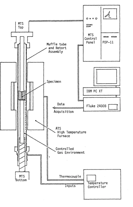
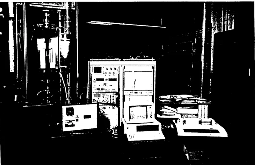
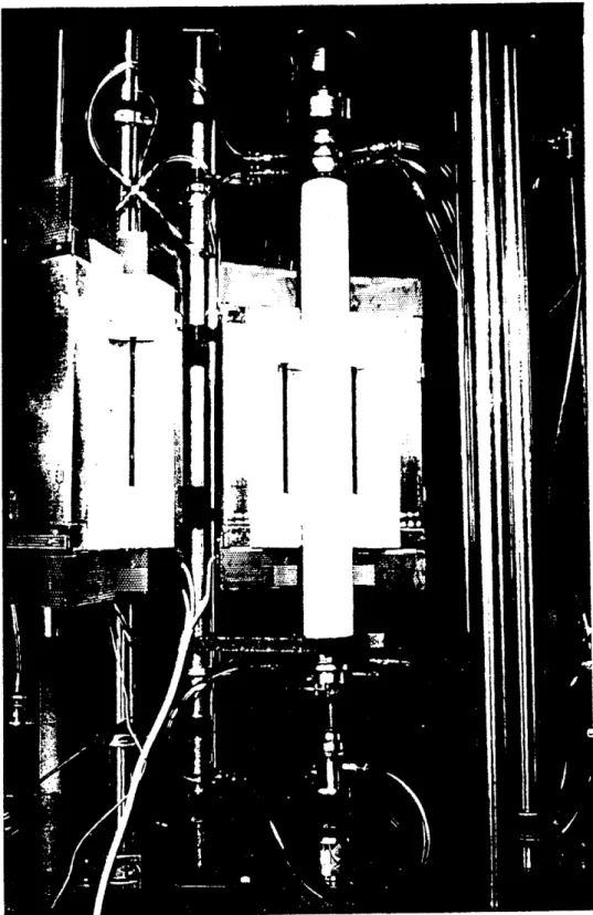
3.2 Equipment for High Temperature Testing 61
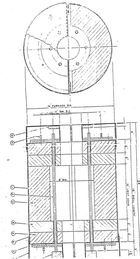
3.2.1 Furnace and Temperature Controller 62
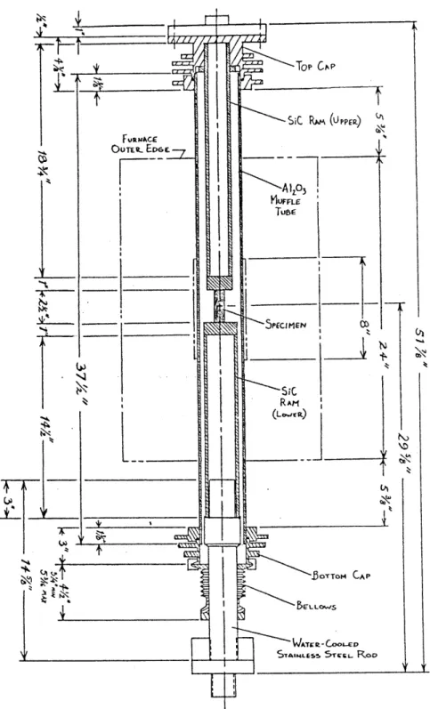
3.2.2 Muffle and Retort Assembly 67
3.2.3 Gas Control System 80
3.2.4 Auxiliary Sytems to the Retort Assembly 86
3.2.5 Data Acquisition and Control System 86
3.3 Testing Procedures Under Short-Term Compressive Loads at Elevated
Temperatures and Controlled Gas Environments 90
3.4 Equipment for Microstructural Characterization 94 3.4.1 Optical and Scannng Electron Microscopes 95
3.4.2 Mercury Porosimeter 101
3.4.3 Dry Density Measurements 102
3.5 Summary 103
4. MATERIALS AND TESTING PROGRAM 105
4.1 Synopsis 105
4.2 Materials Tested 105
4.3 Thermomechanical Testing Program 111
4.4 Microstructural Characterization Test Program 117 5. COLD-PRESSED SINTERED HIGH-ALUMINA AND HIGH-CHROMIA
MATERIALS 123
5.1 Synopsis 123
5.2 Specimen Preparation 124
5.4 Elevated Temperature Behavior of As-Manufactured Materials Under
Uniaxial Short-Term Compressive Loads 140
5.4.1 Behavior Under Monotonic Compressive Loads at Constant
Temperature in Air Atmosphere 140
5.4.2 Behavior Under Constant Compressive Loads at Constant
Temperature in Air Atmosphere 164
5.4.3 Behavior Under Constant Compressive Loads and Increasing
Temperatures in Air Atmosphere 181
5.4.4 Behavior Under Cyclic Compressive Loads at Constant
Temperature in Air Atmosphere 184
5.4.5 Behavior Under Monotonic Compressive Loads and Constant
Temperatures in Reducing Atmosphere 188
5.4.6 Effect of Limited Thermal Cycling on the Material Behavior 194 5.5 Elevated Temperature Behavior of Slag-Impregnated Materials 198
5.5.1 Behavior Under Monotonic Compressive Loads at Constant
Temperature in Air Atmosphere 198
5.5.2 Behavior Under Monotonic Compressive Loads at Constant
Temperature in Reducing Atmosphere 205
5.6 Microstructural Characterization of Virgin and Tested Materials 205
5.6.1 Microscope Observations 205
5.6.2 X-ray Microanalysis 239
5.6.3 Results of Porosimeter Tests 241
5.6.4 Dry Density Measurements 243
5.7 Summary 243
6. HOT-PRESSED HIGH-ALUMINA AND HIGH-CHROMIA MATERIALS 253
6.1 Synopsis 253
6.2 Specimen Preparation 253
6.3 Elevated Temperature Behavior of As-Manufactured Materials Under
Uniaxial Short-Term Compressive Loads in Air Atmosphere 254 6.3.1 Behavior Under Monotonic Compressive Loads at
Constant Temperature 254
6.3.2 Behavior Under Constant Compressive Loads at
Constant Temperature 280
6.4 Microstructural Characterization of Virgin and Tested Materials 285
7. FUSED-CAST HIGH-CHROMIA MATERIALS 293
7.1 Synopsis 293
7.2 Specimen Preparation and Block Characterization 293 7.3 Elevated Temperature Behavior of As-Manufactured Materials Under
Uniaxial Short-Term Monotonic and Constant Compressive Loads at
Constant Temperature in Air Atmosphere 295
7.4 Microstructural Characterizations of Virgin and Tested Materials 305
7.5 Summary 314
8. MATERIAL DATABASE 317
9. CONCLUSIONS 324
9.1 Summary of the Present Work 324
9.2 Summary of the Main Findings 328
9.2.1 Testing Methodology 328
9.2.2 Behavior Under Monotonic or Constant Compressive Loads 333 9.2.3 Behavior Under Cyclic Compressive Loads 341 9.2.4 Effect of Environmental Factors on the Material Behavior 341
9.2.5 Material Selection 345
9.3 Conclusions 348
9.4 Suggestions for Future Research 351
REFERENCES 354
List of Figures 372
List of Tables 386
APPENDIX A. MATERIAL DATABASE 391
A.1 Thermomechanical Properties 391
A.1.1 Tabular Representation of Thermomechanical Properties 394 A.1.2 Functional Representation of Thermomechanical Properties in
A.1.3 Functional Representation of Thermomechanical Properties in Compression and Low P0
A.1.4 Functional Representation of Modulus of Rupture Data at Elevated Temperatures in Air
A.2 Thermophysical Properties
A.2.1 Tabular Representation of Thermophysical Properties
A.2.2 Functional Representation of Thermophysical Properties in Air APPENDIX B.
APPENDIX C.
APPENDIX D. APPENDIX E.
REGRESSION ANALYSIS OF THERMOMECHANICAL
AND THERMOPHYSICAL DATA 472
SUMMARY OF CAVITY CHARACTERIZATION FOR
CPS-OOA-10C UNDER VARIOUS TESTING CONDITIONS 560 ADDITIONAL INFORMATION ON THE RETORT SYSTEM 569
SELECTED RESULTS FROM THE VARIABILITY STUDY 445 447 450 450 466 576
CHAPTER
1
INTRODUCTION
1.1 PROBLEM DESCRIPTION
The general application area is high temperature and pressure containment vessels. High temperature containment vessels are important components used in many industrial facilities such as fossil power plants, coal gasification plants (Bakker et al., 1984; Bakker and Stringer, 1981; Chen and Buyukozturk, 1984; Kennedy, 1979), petroleum refinery units (Crowley, 1984; Crowley and Johnson, 1972; Gilchrist, 1977; Wygant and Bulkley, 1954), blast furnaces (ISI, 1968), steel convertors, metal smelting and refining industry (Hugget, 1966; McGannon, 1964), boilers, petrochemical plants, steam-raising plants, ammonia plants, incinerators, and cement kilns. These vessels are usually composed of an outside steel shell and layers of refractories. Refractory linings protect the steel shell from high temperatures, and attack by gases and process by-products. The linings are usually composed of a dense layer next to the hot face and a layer of insulating material next to the steel shell. The linings can be either monolithic or composed of bricks that are jointed together using a mortar material. Cooling systems can be used to keep the shell temperature at certain predetermined levels.
In most of these applications the refractory linings used to protect the steel shell are subjected to the action of extremely severe process environments. The operating conditions include a combination of elevated temperatures, high pressures, cyclic mechanical and thermal loads, corrosive gases, and molten by-products that run down the walls of the gasifiers. These severe environments lead to the failure of
the refractory linings. The cost of maintenance and repair of the refractory linings, combined with the cost of down-time of the facility justify a more thorough research aimed at producing better linings.
The conducted research concentrates on a specific application, which is slagging coal gasifiers with brick linings. The gasification process is aimed at converting coal into a suitable and economic gaseous fuel. In slagging gasifiers the refractory layers are composed of dense bricks next to the hot-face and of insulating material next to the steel shell. The dense refractory layer, which is in direct contact with the process environment, is provided to resist high temperature, corrosion, and erosion. The insulating refractory layer, which has a relatively low coefficient of thermal expansion, reduces the shell temperature and increases the thermal efficiency of the system. The bricks are usually joined together using mortar material.
The analysis and design of refractory linings is complicated primarily due to the complexity in modeling the material behavior. Such an analysis should consider the refractory material behavior with respect to the effects of monotonic and cyclic mechanical loads, elevated temperatures and thermal cycling, environmental interaction such as slags and process gases, and history of thermomechanical loadings. Thermomechanical data on the behavior of the refractory materials in the process environment is unavailable or incomplete.
There is a need for fundamental research to:
o achieve a basic understanding of the refractory material behavior in the process environment;
o assess the role of different manufacturing processes on the thermomechanical properties of the materials;
level to the microstructural characteristics of the material; and
o assemble a database of thermomechanical and thermophysical properties of different refractory materials to be used by designers and manufacturers of these vessels.
The research conducted in the present project at MIT, and reported here is directed towards satisfying these needs.
1.2 SUMMARY OF PREVIOUS MIT WORK
Over the past several years, comprehensive analytical and experimental studies have been undertaken at the Massachusetts Institute of Technology (MIT) dealing with the behavior of monolithic refractory concrete and refractory brick linings. Numerous publications have resulted from these research efforts (Buyukozturk, 1977, 1981, 1982; Buyukozturk and Connor, 1979; Pike et al., 1980; Buyukozturk and Tseng, 1982, 1983; Tseng and Buyukozturk, 1982, 1983; Bremser and Buyukozturk, 1982; Buyukozturk and Shareef, 1983, 1984; Chen and Buyukozturk, 1985a, 1985b, 19'85c; Zisman, 1979; Chehayeb, 1985; Hens, 1986; Hens et al., 1986a, 1986b; Ameur-Moussa, 1987; Tseng, 82; Chen, 84).
For the monolithic refractory concrete linings, constitutive models were developed for both dense and insulating refractory concretes applicable to coal gasification vessel linings. For the development, experiments were performed on refractory concrete plate specimens subjected to biaxial compression at various temperatures. Based on the test results, a general hypoelastic model was developed for refractory concretes. A temperature dependent creep model based on the concept of thermorheologically simple material was also developed. For accurate predictions of temperature distribution through the vessel walls a transient heat transfer analysis
capability was developed with the adoption of a finite difference solution. The developed material models and the heat transfer analysis capability were implemented in a finite element program for three dimensional non linear analysis of refractory linings or heat-up and cool-down cycles. This analysis package was used to define optimum design parameters of these complex systems.
The research on brick linings focused on the behaviorial understanding and the determination of the optimal design and operational parameters applicable to high temperature slagging gasifiers. Data was collected from the literature on the thermomechanical and thermophysical properties of high alumina and high-chromia refractories. Temperature dependent material models were developed to represent the material behavior. Emphasis was on the development of a time-independent constitutive model to predict the material response to multiaxial, non-proportional and cyclic loads. The temperature effect is introduced by scaling the stress-strain curves at different levels, with respect to the peak stress and the associated axial peak strain. A power law creep model, a conductivity model for cracked media, and polynomial representations of the thermophysical properties were also proposed. The different models were incorporated in a finite element program. A predictive corrosion model was proposed to study the long-term corrosion process of lining systems. Based on this model, sensitivity studies were performed to identify the important factors characterizing the long term behavior of the linings. Using the finite element program, the thermomechanical behavior of linings with various material combinations, lining geometries, and heating schemes was studied. Based on the findings from the thermomechanical and corrosion analyses, tentative recommendations were made for the design and operation of lining systems.
1.3 INTERACTION WITH OTHER DOE PROJECTS
The research conducted at MIT was sponsored by the Advanced Research and Technology Development (AR&TD) office of the U.S. Department of Energy (DOE). "The objective of the AR&TD Fossil Energy Materials Program is to conduct research and development on materials for fossil energy applications with a focus on the longer-term and generic needs of the various fossil fuel technologies". The program aims "toward a better understanding of materials behavior in fossil energy environments and the development of new materials capable of substantial enhancement of plant operations and reliability" (Judkins and Carlson, 1987).
In this context the current research at the Massachusetts Institute of Technology (by 0. Buyukozturk and F.G. Tamer) focused on the characterization of refractory materials for linings of slagging gasifiers. This combined very appropriately with other related DOE programs which studied similar materials for various applications. The other programs concurrently conducted with the MIT program were:
o High temperature creep behavior of refractory bricks at Iowa State University: (by Thomas D. McGee);
o Effect of slag penetration on the mechanical properties of refractories at the National Bureau of Standards: (by S.M. Wiederhorn and R.F. Krause, Jr.);
o Thermodynamic Properties and Phase Relations for Refractory-Slag Reactions in Slagging Coal Gasifiers at the Pennsylvania State University: (by A. Muan); and
o Alkali attack of coal gasifier refractory linings at Virginia Polytechnic Institute and State University: (by J.J. Brown).
This led to interaction of the MIT researchers with the other researchers, and integration of the work within the materials program. As a specific example of this integration, the MIT program combined some of its high temperature creep data with results obtained at ISU to develop deformation maps, and compared some of its results on slag-impregnated materials with NBS data.
1.4 RESEARCH OBJECTIVES
The general objectives of the work performed at MIT are to:
1. characterize the compressive behavior of refractory ceramics at high temperatures in coal gasifier environments;
2. relate the macroscopic deformation and fracture behavior to the microstructural properties; and
3. develop a comprehensive material database, to be used in studying the thermomechanical behavior of brick-mortar lining systems.
1.5 RESEARCH APPROACH
The approach used to conduct this research may be summarized in the following steps:
1. Review existing material properties and relevant material models. Review standard testing methods and specimen preparation procedures. Establish materials to be tested and thermomechanical testing program.
2. a. Design and develop a high temperature testing facility under controlled gas environment. Establish specific procedures to be followed in high-temperature testing.
b. Establish standard specimen preparation procedures, characterize brick properties, and study material variability. 3. a. Perform short-term uniaxial monotonic compression tests at
constant room and elevated temperatures in air, on as-manufactured and slag-impregnated cold-pressed sintered high-alumina and high-chromia refractories, and as-manufactured hot-pressed and fused-cast high-alumina and high-chromia refractories. Study the strain rate effects on the material behavior under these loading conditions.
b. Perform short-term uniaxial monotonic compression tests at constant room and elevated temperatures in controlled reducing gas atmospheres, on as-manufactured and slag-impregnated cold-pressed sintered high-alumina and high-chromia refractories.
c. Perform short-term uniaxial cyclic compression tests at constant room and elevated temperatures in air, on as-manufactured cold-pressed sintered high-alumina and high-chromia refractories.
d. Perform short-term uniaxial creep compression tests at constant room and elevated temperatures in air, on as-manufactured cold-pressed sintered, hot-pressed, and fused-cast high-alumina and high-chromia refractories.
e. Perform short-term uniaxial constant compression tests at increasing temperatures at different heating rates in air, on as-manufactured cold-pressed sintered high-alumina
refractories.
f. Summarize the deformation and fracture behavior of the studied refractory ceramics under the specific loading and environmental conditions listed in 3a. to 3e.
4. a. Observe microstructural characteristics of virgin and tested materials (such as the size, distribution, orientation, type, and interaction of cavities, and phase distributions) using stereoscopic and Nomarski optical microscopes and a scanning electron microscope.
b. Study the chemical composition of slag-impregnated cold-pressed sintered high-alumina and compare it to the as-manufactured material, and study the chemical composition of as-manufactured fused-cast high chromia refractory using X-ray diffraction.
c. Characterize the open porosity of virgin and tested materials by mercury pprosimeter tests.
d. Measure the dry bulk density of refractory specimens before and after testing.
e. Summarize the microscopic descriptions of the studied refractory ceramics from tasks 4a. to 4d., and relate these observations to the macroscopic properties.
5. Collect the thermomechanical data from the above-mentioned tests. Collect modulus of rupture data at room and elevated temperatures, and thermophysical data from the literature. Assemble the acquired data in a material database as graphs, tables, or functions, in a form to
be used by designers and manufacturers of high temperature vessels. 6. Discuss the obtained results for the different loading and environmental
conditions studied. Compare the behavior of refractory ceramics manufactured by different processing techniques. Relate the macroscopic properties to the observed microscopic characteristics.
1.6 DOCUMENT ORGANIZATION
A literature review of previous work on linings and materials is given in Chapter 2 with emphasis on coal gasification vessels. The system behavior of high temperature containment vessels is reviewed first. The behavior of brittle materials in compression and at high temperatures is reviewed next, as well as the interaction of slags and reducing atmospheres with refractory materials. Finally, testing and related considerations are discussed.
Chapter 3 describes the equipment built for high temperature testing under controlled gas environments, the equipment used for microstructural observations, and the testing procedures. Chapter 4 presents the materials tested, and the scope of the testing program.
The results from the thermomechanical tests and microstructural characterization and the discussion of behavioral trends are presented in Chapters 5, 6, and 7 for cold-pressed sintered, hot-pressed, and fused-cast refractories, respectively. The tests carried out for specimen preparation, block characterization, and the variability study are also described. Results of compression tests at elevated temperatures include monotonic, cyclic, and creep short-term uniaxial compression tests, at constant or increasing temperatures, in air or reducing atmospheres.
In the case of cold-pressed sintered materials, the effects of slag-impregnation and varying strain rates in monotonic tests are examined as well. In the case of hot-pressed materials, different chemical compositions are studied for the alumina--chromia refractories. The microstructural observations of virgin and tested materials under different loading and environmental conditions are reported at the end of each chapter.
For Chapters 2 through 7, except Chapter 4, an indicative synopsis and an informative summary are included for clarity. Chapter 4 only contains a synopsis. The synopsis is a shorter qualitative description of what is presented in the chapter. The summary is more quantitative, and presents major conclusions from the chapter.
Chapter 8 includes a description of the assembled material database. Chapter 9 presents the summary, conclusions, and contributions from the present research, as well as suggestions for future work.
The references, list of figures and list of tables are included after Chapter 9. The material database is presented in Appendices A and B. Details about the microstructure observations are summarized in Appendix C. Additional information on the design of the retort system is presented in Appendix D. Finally, selected results from the variability study are included in Appendix E.
CHAPTER 2
REVIEW OF PREVIOUS WORK ON
LININGS AND MATERIALS
2.1 SYNOPSIS
This chapter is a review of previous work on linings and materials, with an emphasis on the material behavior. The system behavior is reviewed first in Section 2.2, with a focus on slagging coal gasifiers. The system configuration (Section 2.2.1) and causes of lining failures (Section 2.2.4) are similar to other high temperature vessels. However, the operating conditions (Section 2.2.2) and candidate materials (Section 2.2.3) are dependent on the different application. The refractory materials used in high temperature vessels are brittle materials. It is relevant to our work to review the previous work on the behavior of other brittle materials under conditions similar to the ones in our testing program. It appears that there are similarities in the behavior of ceramics, racks, and concretes in compressive loading at high temperatures. The behavior of brittle materials in compression and at elevated temperatures is reviewed in Sections 2.3.1 and 2.3.2 respectively. Our test program also examines the effect of slag-impregnation and reducing atmospheres on the thermomechanical behavior of refractory materials. Previous work in this area (Section 2.4) concentrated on the chemical interaction between the environment and the materials), and not as much on the effect of the environment on the thermomechanical properties. The test procedures and interpretation of results are important for the assessment of the mechanical properties of brittle materials, and
are reviewed in Section 2.5. Finally, the relation of present research to previous work is presented in Section 2.6.
2.2 SYSTEM BEHAVIOR OF HIGH TEMPERATURE CONTAINMENT
VESSELS
2.2.1 System Configuration
Gasification vessels, in which coal is converted to combustible gas, are usually cylindrical in shape, from 100 to 250 feet in height, and 15 to 60 feet in diameter. The vessels are usually composed of an outside steel shell and refractory linings. The main purposes of the refractory linings are to maintain and improve the thermal efficiency of the system, and to protect the steel shell from high temperatures, and severe environments. The linings are either made of monolithic refractory castables (Fig. 2.1), or from refractory bricks jointed together using a mortar material (Fig. 2.2). The refractory linings are usually composed of a dense layer next to the hot face and of insulating material next to the steel shell. The dense refractory layer, which is in direct contact with the' process environment, is provided to resist high temperature, corrosion, erosion and abrasion. The dense refractory layer usually has high thermal conductivity and better thermomechanical properties and thermal shock resistance. The insulating refractory layer, which has a relatively low coefficient of thermal expansion and a low heat capacity, reduces the shell temperature and increases the thermal efficiency of the system. In the case of monolithic linings, steel anchors extending from the steel shell into the refractory linings are usually used to enhance the integrity of the system. In the case of brick linings, the bricks are joined together using mortar material. The bricks are in the form of trapezoidal blocks with either a straight edge (Fig. 2.3a), or a circular edge (Fig. 2.3b). They may sometimes
Steel shell Insulating refrac-tory concrete Dense refractory concrete -- Top view Side view
High temperature monolithic linings (Tseng, 1982)
Hoop cracks Radial cracks Pores Anchors Radial Gap Axial cracks Figure 2.1
iL
K
Ho Fa Slag Refractory ce Cool Face HotHigh temperature brick linings (Chen, 1984)
Steel Cooling
(a) straight edge brick
Figure 2.3
(b) circular edge brick with grooves and keys
be keyed together for mechanically interlocking them anticipating an improvement in the system integrity (Fig. 2.3b). Cooling systems are frequently used to keep the shell temperature at certain predetermined levels. A compressible material layer can be used between the steel shell and the refractory linings to relieve some of the stresses caused by the linings expansion at elevated temperatures.
2.2.2 Operating Conditions
In slagging coal gasifiers the operating conditions are extreme (Cooper and Ellingson, 1984; Bakker and Stringer, 1981; Crowley, 1975). Generally, the range of operating temperatures in slagging gasifiers is 2400OF - 33000F (13150C - 18160C). Ash is generally present as molten slag that runs down the walls of the gasifiers, and is corrosive to the linings. Gas pressures in the gasifiers usually range from atmospheric to 1000 psi (6.9 MPa). Gases present consist of H20 (steam), H2, CO, CO2 and small amounts of CH2, N2, NH3 and H2S. These gases are usually reducing in nature, and a typical value of the partial oxygen pressure during operation is 10- 8 a t m . (10-3Pa).
In representing the gasifier environment in the laboratory, two essential parameters are: the partial oxygen pressure (PO2) and the slag.
The gas environment is important because it can directly affect the material thermomechanical and thermophysical properties, and also affect the interaction between the molten products in the process environment and the refractory materials. Different researchers use different gas mixtures to simulate coal gasification atmospheres. Different methods are used by Robins and Mauer (1981), Washburn (1982), Muan (1983 and 1987), McGee (1984), Bakker et. al. (1984), Easler (1985), Greenberg and Peoppel (1985), and Wiederhorn- and Krause (1986). Some of these
are summarized in Table 2.1.
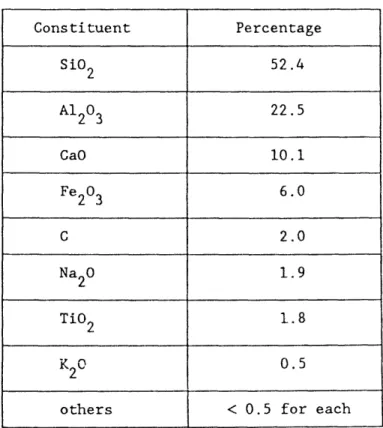
Coal-Ash slags are complex multicomponent silicates that are mainly composed of SiO 2, CaO, A1203, FeO and Fe20 3. Two quantities are usually used to characterize the slag: their base-to-acid ratio and their ferritic content (Kennedy, 1980; Washburn, 1982). The P0 of the atmosphere can be back calculated from the
0 2
ferritic content of the slag (Washburn, 1982).
2.2.3 Candidate Materials
The candidate materials for high temperature applications are refractories. Refractoriness is usually defined as the capability of maintaining a desired degree of chemical and physical identity at high temperatures and in the environment and conditions of use (Budnikov, 1964). The main types of refractory materials are: refractory castables, plastic refractories, ceramic refractories, refractory fibers, and refractory metals (Crowley, 1984). The uses of refractory materials are numerous (ACI, 1982; AFML, 1963; Duffy, 1980; Norton, 1968; Shaw, 1972; Wygant and Crowley, 1964).
In general two types of refractory materials have been used in slagging gasifiers: high-alumina and high-chromia refractories (Bakker and Stringer, 1981; Sweeney and Cross, 1982; McGee, 1984). The high-alumina refractories are known for their good resistance to thermal shock (Bandyopahyay et al., 1983), while high-chromia refractories are known for their good corrosion resistance (Bakker et al., 1984; Bonar et al., 1980; Kennedy, 1980; Washburn, 1982).
2.2.4 Causes of Linings Failure
Researcher Gas Mixture Used
Aim Achieved
P0 2 -8
Muan,87 C02, H2 Maintain P2 typical 10 atm.
2
of slagging coal @ 14000C gasifiers
-6 -18
McGee,84 CO, CO2 Control P 10 - 10 atm.
2
Easler,85 Medium-Btu Control P0 P < 10 12atm.
Coal Gas 2 2
30%H2, 44%CO, 10%CO
2 , 1.4%N2
0.6%H2S, 14%H20
Greenberg et.al., Represent slagging 10- 8 10-9atm.
1985 coal gasifier
environment
Robins and Mauer 20%CO, 15%C02 Coal gasification
1981 25%H2, 40%H20 environment
-6 -9
Washburn, 1982 NH3P N2 Control P2 10 - 10 atm.
2
Wiederhorn and N2 Suppress Distilla- 10 4atm.
Krause, 1986 tion of Cr2 03
Table 2.1 Gas atmospheres used by different researchers to simulate coal gasifier
environments
observed and studied. Failure can occur by degradation of the mechanical properties of refractories at elevated temperatures, through cracking, crushing, and spalling of the refractory materials under thermomechanical loadings, by creep rupture, by joint failure of the brick-mortar system, by disintegration of the refractories under gas attack, and by corrosion or erosion due to slag attack.
2.3 REVIEW OF BRITTLE MATERIALS BEHAVIOR 2.3.1 Behavior of Brittle Materials in Compression
The fracture of brittle solids in tension appears to be well understood. On the other hand the fracture of brittle solids in compression has been less studied, but is as important (NMAB, 1983). The fracture of brittle solids in compression is a tensile phenomenon at the atomic scale. Fracture originates from pre-existing cavities or from the nucleation of cavities next to stress concentrations at grain boundaries, aggregate interfaces, and triple junctions. Under triaxial compressive applied loads unequal compressive forces are produced and result in shear stresses along the pre-existing or nucleated cavities. These cavities are usually differentiated in two different classes: cracks and pores. The criteria that is sometimes used to differentiate between cracks and pores is the aspect ratio of the cavity. The interactions between different cracks, and between cracks and pores have been studied previously.
Griffith (1924) was the first one to study the fracture of brittle solids in compression. He postulated that the strength of solids is smaller than the theoretical strength due to small cracks formed during manufacturing or treatment. The Griffith criterion indicated a compressive strength equal to eight times the tensile strength independently of triaxiality effects. Orowan -(1949) re-interpreted the work of
Griffith, and showed that the cracks can produce a stress concentration that reaches the theoretical material strength, for an applied stress that is much lower. Later on, McClintock and Walsh (1962) modified the Griffith criterion, by taking into consideration that cracks may close under a certain combination of triaxial stresses, thus allowing normal and frictional stresses to be carried across the surfaces of the crack. For the crack to close the applied stress has to be larger than a critical value Sc. Closed cracks can carry an effective normal stress on the surface equal to the value of the applied stress less the critical stress ac, and can also carry shear stresses. The frictional shear stress for the crack to grow is equal to a friction coefficient
times the effective normal stress. This theory gives the compressive strength under confining pressure with respect to the uniaxial compressive strength. Nemat Nasser and Horii (1982) studied the problem further by studying analytically the problem of kinked extension of an initially closed crack under far-field compression, which may undergo frictional slip. According to the study the kinks first grow gradually under increasing axial compression in a stable growth manner, but after the kinks reach a certain length the rate of growth increases dramatically, and the kinks grow in an unstable manner at the final stages of loading.
According to a recent NMAB report (1983) these theories are based on overall fracture developing mainly by splitting due a single crack, which has dimensions comparable to the size of the specimen. This mode of failure in compression involves the extension of a single crack in a direction parallel to the maximum principal stress direction (Figure 2.4), and is termed extrinsic (NMAB, 1983). However, when the existing microcracks are small compared to the size of the specimen, they may link up and form a local region of increased shear compliance. This region develops further under increasing compression to produce a shear fault instability that will lead to
Pre-existing - Secondary Crack Crack .-3 o3 3 + (a) (b) 0"I 0"I
Extrinsic fracture behavior (NMAB, 1983) Figure 2.4
failure in a direction inclined to the principal stress direction (Figure 2.5). This second mode of failure is termed intrinsic (NMAB, 1983). The intrinsic mode is usually observed in tougher materials. The extrinsic mode of fracture is a mode I. In the intrinsic mode of fracture, however, experimental evidence suggests that fracture might be obeying a mode II in-plane shear behavior (NMAB, 1983). Both of these modes of failure have been observed in brittle materials.
The behavior of rocks and concrete in compressive loading at room temperature is used as an illustration. There seem to be indication that for rocks subjected to compressive deviatoric stresses, fracture is not the result of a single "Griffith Crack" (Kranz, 1979). Rocks in their natural state have already existing crack-like cavities. Criteria have been suggested to differentiate between the cracks caused by applied stresses and the existing cavities (Spunt and Brace, 1974; Tapponnier and Brace, 1976). These studies show that stress induced cracks are easily differentiated from natural ones mainly by their shape. At loads below 75% of the peak stress, the nature of cracking is mostly intergranular and healed transgranular. At loads abov6 75% of the peak stress, a majority of transgranular cracks is observed. Close to the peak stress, linking of the cracks starts to be a major mechanism. There is evidence that pores did nucleate and grow during loading. Fractures form from the intersection or coalescence of microcavities. One main difference between tension and compression behavior, is that in tension the tensile stress concentration increases with crack length, while in compression the crack extension force is maximum during initial propagation and reduces after that, so that the crack in compression reaches a stable position. Thus, previous researchers have concluded that a macroscopic fault under compression cannot be the result of a single crack, but the coalescence of crack branches, given boundaries, and pores. The
()
3
(b)
Intrinsic fracture behavior (NMAB, 1983) Figure 2.5
interaction between these cracks have been studied extensively (Brace & Bombolakis, 63; Hoek & Bieniawski, 65; Lange, 68; Swain & Hagan, 78; Kranz, 79; Fonseka et. al., 1985). "En echelon" cracks (Figure 2.6) were found to link either parallel to the applied stress, or in a shear linkage. "En passant" interaction (Figure 2.7) occurs when cracks approach each other on different planes, and at first shear stresses deflect the crack paths away (KII/K I is positive), and then toward each other (KII/KI is negative). The linkage occurs when the tip of one crack runs in the side of the other. The interaction of pore and a crack is more complex. Cracks can be deflected from their preferred path by the region of a high stress concentration next to a void. The hole concentrates Mode I stresses, and if large Mode II stresses are present, KII/KI can be large enough to deflect the crack into the hole. Kranz (1979) observed cracks running into pores at orientations varying from 100 - 200 of the principal stress
directions up to 900 of the principal stress direction. A microcrack model of rock inelasticity was developed by Kachanov (1982a, 1982b) that helps explain the basic features of the macroscopic behavior. The model assumes that frictional sliding on microcracks is the major mode'of inelasticity at moderate compressive stresses. This represents the first stage of inelasticity. At higher stresses, kinking and propagation of microcracks is considered to be a major mechanism. A comprehensive testing program followed by microstructural analysis was conducted by Wong (1982a) for Westerly Granite, in compression under different conditions of pressure and temperature. Samples retrieved prior to failure showed a lot of transgranular cracks at low angles (<150) to the maximum compression direction, as well as many high angle (>150) transgranular cracks. In the post-failure samples, most cracks were inclined at 150 to 450 to the maximum compression direction. Outside this localized region of deformation, bands of axial cracks were observed. The inclined cracks join
Applied
Load
Stage
1
Stage 2
Stage 3
Applied
Load
'
"En Echelon"
"En Echelon" crack interaction
4I
/
J
4
T
"En Passant" crack interaction
Applied
Load
"En
Passant"
Applied
Load
Figure 2.7up to form a shear zone, and eventually overcome the resistance formed by other crack arrays to form a shear fault. Some microcracks were also observed perpendicular to the applied principal stress direction. The explanation was that unloading can result in tension cracks that are oriented as such (Boland and Hobbs, 73; Wong, 82a). Samples deformed at higher pressure or temperatures showed a higher crack density.
Similar studies have been conducted on concrete. Concrete contains bond cracks before it is loaded (Krishnaswamy, 1971). During initial loading in compression some pre-existing microcracks might close, and no propagation of microcracks is observed until about 30% of the peak strength. With increasing loads up to 70% of the peak strength the density of the bond cracks increases. As the load reaches about 90% of the ultimate load, bond cracks are joined by mortar cracks, preferentially on large aggregates instead of small aggregates (Shah and Slate, 1965). At peak stress crack networks are present, and in the post peak region spalling of the concrete occurs. The bond cracks occurring at the aggregate-mortar interface may be caused by tensile or shear stress or a combination of both. The mechanism of cracking may include sliding and/or separation at these interfaces (Buyukozturk et al., 1972). Local tensile failure seems to be the dominant mode of fracture of concrete in compression (Raju, 1970). At lower load levels, the cracks are parallel to the applied load but near the ultimate load these vertical cracks connect in what appears to be a shear failure (Robinson, 1965). The mechanism of crack extension in a brittle solid is tensile splitting at the atomic level (Shrive and EI-Rahman, 1985; Soon, 87). However with the load approaching the ultimate, shear cracks are observed as well
Concrete has also been tested extensively in cyclic compression. (Award and Hilsdorf, 1972; Tepfers, 1982; Raithby, 1979; Hsu, 1981; Sparks, 1982; Holmen, 1982; Bresler, 1976; Soon, 1987). It is interesting to briefly review existing behavioral trends, since our tests involve cyclic loading. The uniaxial monotonic stress-strain curve is an envelope curve to the cyclic stress-strain response. The intersection between the unloading branch with the next loading branch is called a common point. If the maximum cyclic stress is above the common point envelope, non-recoverable strain is produced and failure will occur after only a limited number of cycles. On the other hand, if the maximum cycle stress is below the common point envelope, failure will occur after a large number of cycles. At certain stress levels hysterisis loops are obtained. The intersection point of the stabilized hysterisis loop are called stability points. If the maximum cyclic stress is below the stability points envelope, identical hysterisis loops are produced, and failure of concrete under cyclic stresses is unlikely. The common and stability points envelope were found to be at about 80% and 75% of the monotonic strength of concrete respectively (Lam, 1980), and independent of the minimum load levels. Microcracking of concrete in cyclic compression appears to be more progressive (Raju, 1970; Shah and Chandra, 1970; Stroeven, 1979). The density of bond cracks is 15% more than the one observed for monotonic compression tests. The mortar cracks were more prominent than bond cracks. The low cycle (high stress) fatigue life of concrete in compression was observed to be very sensitive to the maximum cyclic stress, but the minimum cyclic stress did not appear to have a great influence (Soon, 87). The low cycle fatigue life was divided into three major zones: the first one was composed of initial cycles with large deformations, the intermediate range was characterized by uniform hysterisis loops, and just before failure, the deformations picked up again (Soon, 87).
A large variety of constitutive models have been proposed for concrete. They can be classified as: elasticity-based, plasticity-based, endochronic, plastic-fracturing, strain space models, damage-type, and bounding surface models. The first type of models developed and later on improved is based on failure surfaces. A failure surface is defined as the focus in the principal stress space of all peak stresses. These models include: Bresler and Pister (1958), Ottosen (1977), William and Warnke (1974), and Lade (1982). The elasticity models include the hyperelastic models (Chen, 1982; ASCE report, 1982) which express the stresses as a function of a strain energy function, and the hypoelastic models (Chen, 1982; Buyukozturk and Shareef, 1984; Elwi and Murray, 1979) that express the incremental stresses as a linear function of the incremental strains. The elastoplastic strain-hardening models (Chen, 1982; Buyukozturk and Shareef, 1984; Buyukozturk, 1977; Chen and Chen, 1975; Han and Chen, 1985) postulate the existence of a loading surface in stress space which expands from the yield surface to the failure surface as a function of plastic deformation. The plastic strain increments are obtained by an associated flow rule. Most of these previously mentioned models are for proportional loading, and their accuracy decreases with deviation from proportional loading. Bazant and Tsubaki (1980) have proposed a model that take into consideration path dependency. Endochromic models (Bazant and Bhat, 1976,; Bazant and Shieh, 1980) obtain inelastic strains from the variation of an intrinsic time which increases whenever deformation takes place. The concept of fracturing loading surface has been used (Bazant and Kim, 1979) to extend the elastoplastic models to the strain softening range. The concept of bounding surfaces has been used more extensively recently (Fardis et al., 1983; Yang et al., 1985; Chen and Buyukozturk, 1985a; Ameur Moussa, 1987; Dafalias, 1986). In these models a mapping rule associates an image stress
point on the bounding surface with any stress point within the surface. Although this type of model is widely used, disagreement between different researchers still exist on the type of damage parameters to be used.
2.3.2 Behavior of Brittle Materials at Elevated Temperatures
The behavior of ceramics, concretes, and rocks at elevated temperatures is briefly reviewed in this section with emphasis on compressive loading.
The behavior of ceramics at elevated temperatures has been categorized in three different regions (Evans and Langdon, 1976). In the first region, at relatively low temperatures, the behavior of the material is brittle and only a small decrease in strength is observed with temperature. The second behavioral region at intermediate temperatures exhibits a "deformation assisted brittle fracture" (Evans and Langdon, 1976), where the material strength decreases faster with temperature. At elevated temperatures in the third behavioral region a ductile behavior is observed. The different behavioral regions have also been observed for an alumina ceramic, where at 23000F the failure is by fractire and at 23180F an upper yield stress and a lower yield plateau are observed (Kingery et. al., 1976). The effect of slower strain rates has been compared to the effect of higher temperatures for alumina ceramics (Kingery et. al., 1976). The decrease in strength with temperature is usually monotonic. However some exceptions have been observed. Tests on alumina-silica (Miller and Davies, 1966) showed a small decrease in MOR from room temperature to about 15000F. Then, from 15000F to about 2000F an increase in MOR with temperature was observed. A 90% dense alumina exhibit a MOR of about 2500 psi at 1500F compared to 3500 psi at 20000F. This increase in strength has been observed by other researchers as well (Hunt and Bradley, 1941; Folk and Bohling, 1968). This
phenomenon does not occur in all ceramics systems, but is observed in systems containing more than one mineralogical phase. The increase in strength at intermediate temperature is more pronounced for systems containing both crystalline and glassy phases. This effect was less important in systems containing two different crystalline phases, but no glassy phases. At temperatures higher than 20000F a rapid drop in MOR with temperature is observed. A super-duty fireclay shows a drop from a MOR of about 2200 psi at 20000F, to a MOR of 200 psi at 2500F (Miller and Davies, 1966). Similar results have also been observed for hot-pressed silicon nitride (Clarke, 1983) where the flexural strength shows no degradation up to temperatures of about 9000C and then decreases monotonically at a rapid rate for higher temperatures.
The behavior of concrete at elevated temperatures was studied by different researchers (Thelandersson, 1974; Anderberg and Thelandersson, 1976; Khoury et. al., 1985). The compressive strength was observed to decrease slowly with temperature from 250C up to 4000C, and rapidly from 4000C to 8000C at which it is reduced to 25% of its original room temperature value. The static elastic modulus at 4000C is about 50% and at 8000C is about 15% of its room temperature value. It is shown by Anderberg and Thelandersson (1976) to compare well with the dynamic modulus obtained by Cruz (1966). The material behavior is initially linear elastic from room temperature up to 4000C. The constitutive model of the material is based on a representation of strain as the sum of four different strain components:
1. a thermal strain component including shrinkage, measured on unstressed specimens under variable temperature, and depending only on temperature;
temperatures, and depending on stress, stress history, and temperature; 3. a time-dependent creep strain measured under constant stress at
constant temperature, and depending on stress, stress history, temperature, and time; and
4. a transient strain measured from the constant stress increasing temperature tests, and depending on stress and temperature.
The high temperature behavior of refractory concrete is similar to the high temperature behavior of ceramics. A review by McCullough and Rigby (1972) reported two kinds of variation of strength with temperature for alumina refractory concretes: (1) a decrease in strength, levelling off over the range of 400-10000C, followed by an increase in strength with temperatures above 11000C, and (2) an increase in strength at temperatures around 2000C followed by a decrease in strength to a minimum value at about 12000C, followed by a further increase in strength at temperatures above 13000C. The increase in strength of refractory concrete at high temperatures is similar to the one observed for certain ceramics, as discussed at the beginning of this section. In the case of the refractory concrete the increase in strength was attributed to the formation of a ceramic bond which began to form at about 11250C. However, the variation of static modulus with temperature reported by McCullough and Rigby (1972) was not similar to the one seen in ceramics. They observed an increase in the values of E until a flat maximum occurred at temperature of about 900 to 11000C. The values of E started decreasing sharply at temperatures above 12000C. Heindl and Post (1954) not only reported an increase in compressive strength in the temperature range 11000C - 12000C, but an increase in tensile strength as well. An increase in compressive strength for both dense and insulating
refractory concretes for temperatures in the range 11000F - 15000F was also reported (Tseng and Buyukozturk, 1981).
As for the case of brittle solids in compression, the behavior of rocks under compressive loads at high temperatures is the best understood. Griggs et al. (1960) established that in the brittle regime the failure stress is relatively insensitive to temperature. This was confirmed by other studies (Handin and Hager, 1958; Raleigh and Paterson, 1963). Failure and post failure behavior of Westerly granite at pressures up to 400 mPa and temperatures up to 700 C, showed that for dry samples the effects of temperature and strain rate on the failure stress are not significant relative to that of pressure (Wong, 1982b). The independence of strength on strain rate in the brittle regime has also been reported by Brace and Martin (1968) who observed a strength increase of only 10% over three orders increase in strain rate. The failure stress is expected to increase with pressure, and its pressure dependence to decrease with temperature. But this does not always agree with the reported data (Griggs et al., 1960). For the same pressure the reduction in strength is about 20% from room temperature to 5000C for Westerly granite, but at temperatures above 5000C an accelerated downward trend is observed (Wong, 1982b). In post-failure samples clear cut faults were observed, and the localized zones grew wider at higher temperatures. Both temperature and pressure tend to stabilize the post-failure behavior. The transition temperature for stable failure in Westerly granite was observed to be at 6600C at 80 MPa, 450oC - 5500C at 250 MPa, and 350 - 4200C at 400 MPa (Wong, 1982b), and at 25 - 3000C at 500 MPa (Griggs et al., 1960). The extent of thermal cracking at a given pressure was found to increase with increasing temperatures (Wong and Brace, 1979). But based on the data of Wong (1982b) thermal cracking is not responsible for the decrease in strength with temperature,
because the failure stress does not show a sharper decrease with temperature at lower pressures. The review of the post failure behavior of rocks at high temperature was reviewed extensively by Paterson (1978). The microstructure of Westerly granite at different loading combinations of temperature and pressure were also examined by Wong (1982b), and a large number of high-angle cleavage cracks, and shear cracks at 450 were observed. Cracks nucleation was also observed next to the pre-existing pores in the material. The proportion of high-angle cracks was observed to increase with an increase in pressure and temperature. The sequence of failure suggested by Wong (1982b) is by first extension of the high angle (15-450) cracks to full length, and any further slip can occur by overcoming the frictional resistance in the pre-failure region. The axial cracks networks act as barrier to linking up of the coplanar shear cracks. The failure starts by collapse of these barriers, and transfer of the localized stresses to the next barrier. This is followed by linking between the barrier and the inclined shear crack. This results in a reduced frictional resistance along the incipient fault, until the residual stress level is reached along the entire fault spanning the sample. A 'thorough review of mechanical, physical and thermal properties of granite rocks has been done by Heuze (1983). His data shows decrease in modulus with temperature to about 10% of its room temperature value at 600 C for Stripa and British granites, and a decrease to about 5% of its room temperature value at 1200°C for Salisbury granite. Dry granite melts at about 10500C. The Brazilian tensile strength for Westerly and Charcoal granites was found to decrease from about 14 MPa at room temperature to about 10 MPa at 5000C, but then decrease much faster to almost zero at 10000C. The qualitative decrease of compressive strength with temperature was similar to the tensile strength variation for dry Westerly granite. However, the compressive strength of charcoal granodiorite