Design of Optimal Motion
for Flight Simulators
by
Jehuda Ish-Shalom
B.S.E.E., Technion, Israel Institute of Technology
(1974)
M.S.E.E., Technion, Israel Institute of Technology
(1978)
Submitted in Partial Fulfillment
of the Requirements for the
Degree of
Doctor of Philosophy
at the
Massachusetts Institute of Technology
December, 1982
©
Massachusetts Institute of Technology, 1982'
Archives
Signature of Author
Interdepartmental Pro
n
o-e
g
Certified by
Laurenc; R. Your
Certified by
William M. Sieb
Certified by
Bernard C. L
Certified
by
4Rqert V. Ken
MASSAH&P 0ISTITLTEHOF TECHNOLOGY
HAROLD
Y1
WPMAN, CHAIRMAN
MAR
I1
3
DEPARTMENTAL
LIBRARIES
December 21, 1982
ng
Committee Chairma
)ert
Committee Membe
evy
Committee Membe
yon
Committee Membe
GRJADUATE
COMMITTEE
n
MiTLibraries
Document Services
Room 14-0551 77 Massachusetts Avenue Cambridge, MA 02139 Ph: 617.253.5668 Fax: 617.253.1690 Email: [email protected]http: /libraries. mit. edu/docs
DISCLAIMER OF QUALITY
Due to the condition of the original material, there are unavoidable
flaws in this reproduction. We have made every effort possible to
provide you with the best copy available. If you are dissatisfied with
this product and find it unusable, please contact Document Services as
soon as possible.
Thank you.
Due to the poor quality of the original document,
there is
3
To my parents Moshe and Dina
Who brought me up to reach this day
To my wife Niti and children Amir and Alon
Who suffered the burden of this thesis
Design of Optimal Motion
for Flight Simulators
By
Jehuda Ish-Shalom
Submitted to the Interdepartmental Program in Bio-Medical Engineering on December 21, 1982 in partial fulfillment of the requirements for the degree of Doctor of Philosophy in Bio-Medical Engineering.
Abstract
An abstract simulator design problem is formulated as follows: Given a dynamic system, S', called the actual system and another dynamic system, SS, called a
simulator for Sa, and given a function which drives the system S, the problem is
to find an operator, properly constrained, which will generate the input to S' on the basis of the input to Sa, such that the discrepancy between the outputs of Sa and S' will be as small as possible. This abstract simulator design problem is formulated as an optimal control problem and in the linear-quadratic case this problem is decomposed into two separately solvable subproblems: (i) deterministic and (ii) stochastic. Both subproblems are solved; the stochastic one for the Gaussian case only. Examination of the properties of the solution reveals a parallel decomposition theorem and the dependence of the simulator design on the given parameters. These and other properties of the solution enable the extension of the solution to include output nonlinearities in S' and Sa and for a time varying system representation for the expected input to S'. These properties make it possible to develop a
methodology for the design of optimal simulators.
Next, the solution of the abstract simulator problem is applied to the design of motion generation for moving base flight simulators. The optimization criterion
selected is a norm of the difference between the physiological outputs of the
vestibular organs of a pilot in an imaginary reference airplane and those of a pilot
in the simulator. Vestibular models based on physiological and psychophysical
experiments were used. As a consequence, a new design methodology is suggested for the design of the motion of moving base flight simulators.
As a demonstration of this methodology several design examples were solved and simulated. The results conform the set of empirically found design rules used by experienced engineers to determine the filter parameters of flight simulator motion
generation systems. In addition several designs were implemented and were tested
by twenty pilots. These designs were implemented for the pitch and surge axes on
a Link GAT-1 general aviation flight simulator. These tests also suggest a possible
reason for many general aviation accidents that occur due to a stall during a landing approach. Last, a generalization to a nonlinear motion generation system
6 Abstract
was implemented, which can be easily applied to the full six-degrees-of-freedom
case.
The design method that we have obtained can also be used for model following or
robotic motion design.
Thesis Supervisors:
Laurence R. Young
William M. Siebert
Bernard C. Levy
Robert V. Kenyon
Professor of Aeronautics and Astronautics
Professor of Electrical Engineering Assistant Professor of Electrical Engineering Assistant Professor of Aeronautics and Astronautics
Acknowledgments
I wish to thank Prof. Laurence R. Young for introducing me to research
connected with the vestibular system and for providing the environment and support for this work; Prof. Rafhael Sivan for suggesting the topic and for his help during varying stages of this work; Prof. Bernard C. Levy for being a friend and for guidance and discussion throughout this work; Prof. William M. Siebert for advice, guidance of the general direction of this thesis and for his cordial support and encouragement at anytime and in particular-at difficult times. Thanks are due also to Prof. Robert V. Kenyon for his interest in this work and for comments on chapter VII and for supporting the construction of the GAT-1 Ows by serving as faculty advisor to the 16.62 students.
Thanks to Jen-Kuang Huang who helped in preparing the two degree-of-freedom example given in chapter V and to Paul A. Wetzel for his help with the statistical analysis in chapter V-1. Comments on various chapters by Anthony P. Arrott
(i,
VIE), Russ Taylor (ff, IIM), Prof. Shankar Sastry (JY), Ching-Meng Chew (IT) and
Sew Wah Tay
(V_1)
are gratefully acknowledged.For introducing me to various aspects related to this work I would like to mention with thanks: Chuck M. Oman-introduction to vestibular function and helpful comments as a subject in the simulator experiments; Prof. Walter M.
Hollister for giving me the feeling of real flight in his 16.64 course and being a
subject in the experiments; Russell Parrish and Roland Bowles from NASA Langley
Research Center, W. Harrington from Wright Patterson AFB, Dick Bray, A. Daivd
Jones from NASA AMES Research Center for demonstrating and discussing large research simulators; my two brothers Carmel and Yaron who shared their pilot experience with me.
The guest welcoming atmosphere of the MIT Artificial Intelligence Lab. made
it possible to substantially enhance my work through the use of MACSYMA. I would also like to thank George J. Carrette (GJC) for extending MACSYMA for
my application, Jeffrey P. Golden (JPG) and Ellen Golden for their help with the MACSYMA system and to Oded A. Feingold (OAF).
8 Acknowledgments
The assistance of the 16.62 students George C. Ranney and Frahad Zarinechi,
and that of Allan R. Shaw and Robert L. Renshaw in the experimental work was
much appreciated.
And last I wish to express gratitude to Sherry Modestino for her help in the
Lab. and in preparing this manuscript and to all the subjects in the experiments
and in particular to Ian McArthur, Jerry Weiss and John Hansman for their long
hours in the "cockpit"; and to my wife Niti for her infinite patience and hard work
on the nice figures and in typing parts of this thesis.
This work was supported by NASA Ames Research Center Grant NSG 2230
and NAG 2-12, and in part by the United States Energy Research and Development
Administration under Contract E(11-1)-3070 and by NASA Grant 1323.
Biography
Jehuda Ish-Shalom received the B.Sc. degree in 1974 and the M.Sc. in 1978,
both in Electrical Engineering from the Technion, Israel Institute of Technology,
and the Ph.D. in Bio-Medical Engineering from MIT in 1982.
In 1970, he developed an ultrasonic mobility aid for the blind which won first
prize in the 1971 contest "Models and Essays in Natural Science and Mathematics," Weizman Institute, Israel. During his undergraduate studies he was awarded a special grant while working at the Medical Electronics Lab. in the E.E. Dep. in Technion I.I.T.. During 1973 he worked as a test engineer at "Elbit Computers," Haifa, Israel. His M.Sc. thesis was on the "Measurement of Eye Movement with a Ferromagnetic Contact Ring." His Ph.D. work was conducted at the MIT
Man-Vehicle Lab. on the "Design of Optimal Motion for Flight Simulators" using
vestibular system models. Dr. Ish-Shalom is currently working as a Research Staff Member in the Robotics Lab. of IBM at IBM Thomas J. Watson Research Center, Yorktown Heights, New-York.
Dr. Ish-Shalom is a member of the Sigma Xi Society. His major research interests are in robotics, medical instrumentation, sensory systems and VLSI circuit
design.
Publications and Reports:
R. Sivan, J. Ish-Shalom and J.-K. Huang, "An Optimal Control Approach to the Design of Moving Flight Simulators," Transaction of IEEE on Systems, Man, and Cybernetics, November, 1982. Also included in the IEEE proceedings of the
international conference on cybernetics and society, Oct. 1980.
Y.Y. Zeevi and J. Ish-Shalom "Measurement of Eye Movement with a Ferromagnetic
Contact Ring," Transactions of IEEE on Bio-Medical Engineering Vol. BME-29, pp. 511-522 July, 1982. Also included in the proceedings of the conference of the Israeli section of IEEE, Tel-Aviv Israel, Sep., 1977.
J. Ish-Shalom, "Head Rotation Monitoring Device," Man Vehicle Laboratory
Report, Department of Aeronautics and Astronautics, Massachusetts Institute of
Technology, June. 1979.
10 Biography
J. Ish-Shalom, "An Ultrasonic Probe-An Aid to the Blind." Submitted the
contest "Models and Essays in Natural Sciences and Mathematics," WEIZMAN
Design of Optimal Motion
for Flight Simulators
By
Jehuda Ish-Shalom
Summary
An abstract simulator design problem is formulated as follows: given a dynamic system, S', called the actual system and another dynamic system, 5', called a
simulator for S', and given a function which drives the system S', the problem is
to find an operator, properly constrained, which will generate the input to S' on the basis of the input to S', such that the discrepancy between the outputs of S' and S' will be as small as possible. This abstract simulator design problem is formulated as an optimal control problem and in the linear-quadratic case this problem is decomposed into two separately solvable subproblems: (i) deterministic and (ii) stochastic. Both subproblems are solved; the stochastic one for the Gaussian case only. An examination of the properties of the solution puts in evidence a parallel decomposition theorem and provides an interpretation of the dependence of the simulator design on the given parameters. These and other properties simplify the solution so as to enable the extension of the solution to include several nonlinear effects.
The study of the nonlinear effects includes three topics. The first topic is an extension of the deterministic-stochastic decomposition to include nonlinear dynamic system equations using a quadratic cost function. This decomposition shows a general method of how to separate and then combine the "open-loop" (deterministic) and the "closed-loop" (stochastic) solutions for the abstract simulator design problem. This is also true for the general control problem appearing in robot control design.
The second topic is the development of a Pseudo Linear Quadratic controller
(PLQ) for linear and nonlinear dynamic systems. The PLQ controller is derived
from the standard Linear Quadratic (LQ) optimal control solution by solving for
12 Summary
a quasi-quadratic cost and a quasi-linear system for each value of the state. This results in a feedback with a leading linear term, i.e. using feedback gains that are functions of the system state rather then constants. Though PLQ is not a solution to any known formulated optimization it is an extension of the standard
LQ control. Furthermore, in the cases tested it has properties that match those
of known optimal nonlinear controllers derived for linear dynamic systems using a nonquadratic cost. On the other hand, PLQ is easier to compute and easier to implement, due to its "linear" form. Many of the PLQ properties still need to be developed including conditions for global stability for the multi dimension dynamic system case. It is expected that the resulting PLQ controller would show similar robustness properties as the LQ controller.
The third nonlinear effect discussed is a sign sensitive cost formulation and solution. The cost function is put into a form that includes a correlation function term that is evaluated between the outputs of the systems S and S. It is shown that, any antisymmetric compressive memoryless output function, cascaded to the linear dynamics of both Sa and S', would lead to a cost function that should include a sign sensitive term. This problem is put into a LQ form which n1o longer has a positive definite cost. It is shown that a unique solution exists for the abstract simulator design problem. Finally, putting all these elements together, enables one to develop a methodology for the design of abstract optimal simulators.
Next, the solution and properties of the abstract simulator problem are applied to the design of motion generation for moving-base flight simulators. The optimization criterion selected is a quadratic norm of the difference between the physiological outputs of the vestibular organs of a pilot in an imaginary reference airplane and those of a pilot in the simulator. Vestibular models based on physiological and psychophysical experiments were used, including consideration of vestibular sensor saturation and the multiplicative nature of the physiological noise in the nervous system, modeled by an antisymmetric compressive memoryless output nonlinearity. The LQ abstract simulator properties imply a 2-2-1-1 physical axis decoupling theorem for the feedback gains, i.e. Pitch-Surge, Roll-Sway, Yaw, Heave axis group
decoupling. The 2 axis coupling is due to gravity. This 2-2-1-1 rule is well known
11 113
to designers of simulator motion systems. What is usually overlooked is that the feed-forward gains do not decouple the same way due to the effect of the airplane dynamics coupling. When axis transformations are included in the motion system implementation, coupling between all six physical axes is obtained-a property not existing in current designs. An example of this effect is the proper motion generation for the falsely called "Coriolis motion sensation" which usually requires a simulator with full 3600 rotation capabilities. Furthermore, a method for use of head rotation measurement is developed which further improves the simulator motion sensation. As a consequence, a new design methodology is suggested for the design of the motion of moving-base flight simulators.
As a demonstration of this methodology, several design examples were solved and simulated. The results conform to the set of empirically found design rules used by experienced engineers: to determine the structure (2-2-1-1 theorem), the initial setting of the pole locations, the expected lower motion fidelity as the poles' frequency increases, cross coupling gain between the linear and rotation motion
input (called g tilt) used in flight simulator motion generation systems.
Twenty pilots tested seVeral of these designs which were implemented for the
pitch and surge axes on a Link GAT-1 General Aviation flight simulator Trainer. These tests confirm the suggested design method, including equal weighting for
the normalized vestibular linear and rotation components. Furthermore, these tests show the effects of motion on the pilot's control for a sudden unexpected flaps-down
transition during level flight. This experiment also suggests a possible reason for
many general aviation accidents that occur due to a stall during a landing approach
due to its similarity to the above experiment. It was found that even very experienced
pilots with more then ten thousand flight hours can easily be confused initially by the motion and make a wrong elevator control. However, they report making the right control. Lastly, PLQ was used to build a nonlinear-motion-generation system
for the Link GAT-1 simulator. This nonlinear design can be implemented easily for
the full six-degrees-of-freedom case.
The examples and pilot tests presented in this thesis are preliminary investigations into the feasibility of the optimal simulator design approach. The results so far
14 Summary
are promising. The causal, linear, time-invariant "optimal" motion system derived
here has parameters of the same order of magnitude as the conventional motion
systems in use today. However, unlike these systems, the "optimal" motion system
can be "tuned" by a non-expert using this computer design method to satisfy a
variety of additional conditions such as: different travel lengths of the simulator,
different flight trajectories, and different emphasis on motion cues. Furthermore,
it makes use of expected future airplane motions, accounts better for hard limits
by use of PLQ and takes into account axis transformations and head movements.
It is simpler to implement and as a bonus gives the control system design for the
motion-base itself.
It is recommended that this design method be transformed into an optimal
motion system design compiler that is capable of transforming a simple minded,
non-expert specification of the required motion system into a flight simulator
motion-generation system. The design method that we have obtained can also be
used for model-following or robot motion design.
, w
Table of Contents
A bstract . . . .
Acknowledgments...
Biography ... Summary.....
. . . 5
..
. . . 7
..
. . . .
9
..
. . . .11
C ontents . . . .
I Introduction ...
.1. Moving-Base Flight Simulator ... 1.2. Survey of Moving Base Flight Simulator Types... 1.2.1. Cascaded systems. ... 1.2.2. Hexapod System... 1.2.3. Articulated Beam System... 1.2.4. Centrifuge Motion System... 1.2.6. In-Flight Simulators, T-33 and TIFS . . . . 1.3. Survey of Present Washout Filters . . . . 1.4. Basic Approach . . . . 1.5. What to Read in order to Design an Optimal Washout System References ... I[Formulation of the Motion Problem ...
1.1. The Flight Simulator ...
11.2.
Modeling of the Airplane Anticipated Motions0.#..
*.. *.0 .. 0 .1.3. Pilot Block Diagram
. . . .0.0.&.0.*.0.*.0.a.1.
. . . .
1.3.1. Conceptual Building Blocks . . . .
1.3.2. Pilot Information Flow and its Uncertainty
. . . .
1.4. Comparison of Airplane Flight to Simulator Flight
. . . .
1.4.1. Comparison of Cockpit Motions...
1.4.2. Comparison of Sensory Measurements . . . .
1.4.3. Comparison of Orientation Estimate...
1.4.4. Comparison of Control Effort . . . .
1.4.5. Comparison of Pilots Performance
. . . .
1.4.6. Experimental Use of Control Effort and Performance Comparison
1.5. Cost Function
. . . .
1.6. Flight Simulator Motion Design Problem ...
1.7. Can the Vestibular Organ Represent All the Inertial Motion Sensors?
1.8. Vestibular Organ Modeling . .. . . .
1.8.1. Vestibular Organ Description...*..*...
11.8.2.
Assumptions in the Vestibular Model Used . . . ..
. . . .
1.9. Axis Systems...
. . 15 . 19. 19
. 20
. 20
. 21
. 22
. 22
. 22
. 32
. 33
. 36
. 39
. 41
. 42
. 44
. 46
. 47
. 50
. 52
. 53
. 54
. 54
. 58
. 59
. 59
. 59
. 61
67
. 69
. 69
. 70
. 71
15
16 Contents
1.9.1. Axis Systems Involved...
...
1.9.2. N otation . . . .
1.9.3. Handling of axis systems . . . .
.9.4. Including head movements
. . . .
1.9.5. Consideration of the Motion Limitation Axis System . . . .
R.10. Abstract Optimal Simulator Problem Statement . . . .
R eferences . . . .
Appendix II.A. Equations of Motion of the Link GAT-1 Simulator
.. 72 . 74 . 75 . 78 . 79
.81
83 87III Solution of the Linear Quadratic Case ...
95
111.1.
Statement of the Linear Quadratic Case . . . . ...
...
97
11.2. Separation Into Deterministic And Stochastic Problems ... 98
111.3. Deterministic Problem Solution ... 100
111.4. Stochastic Problem Solution . . . 103
111.4.1. Solution of the L.Q.G. Optimal Simulator . . . 104
111.4.2. Derivation of the L.Q.G. Optimal Simulator Filter . . . 106
11.5. Properties of the time-invariant L.Q.G. Solution . . . 108
1.5.1. Algebraic Structure of the Algebraic Riccati Equation . . . 109
1 .5.2. Dimension Reduction . . . 115
111.5.2.1. Riccati equation (PS =?) . . . . 115
111.5.2.2. Linear equation (Pf =?) . . . . 118
H-1.5.3. Simulation Filter Simplification in the Symmetric Case ... 123
11.6. Time-Varying Stochastic Problem Solution . . . 125
References . . . . ... . . 128
Appendix III.A. Derivation of Block Equations . . . 129
Appendix III.P. MACSYMA Program . . . 141
TV Nonlinearities...143
M.1. Deterministic-Stochastic Problem Decomposition.*...146
P1.2. Pseudo Linear Quadratic Control . . . a . ... 153
M .2.1. Result for the linear case . . . 154
P1.2.2. Stability proof for the linear case. ... 0.*... .. . ... 156
M.2.3. Example of PLQ control for a linear plant . . . . 161
P1.2.4. PLQ Control of Nonlinear Plants . . . . 162
P1.2.5. Example of PLQ Control for a Nonlinear Scalar Plant ... 164
M.3. Alternative Performance Criteria . . . 167
P .3.1. Introduction . . . 168
P1.3.1.1. Sensor Saturation .-. . . . .. . . . ... 168
P1.3.1.2. Firing Rate Statistics... 170
P1.3.1.3. Correlation Cost . . . ... . . . .0..*...175
P1.3.2. Problem Formulation... . . . 175
P1.3.3. Solution ... ... o...o...177
P1.3.3.1. Deterministic Solution . . . . .. 177 i I
IV.3.3.2.
Stochastic Solution
. . . .
1iV.3.4. Special Properties of the Solution...R eferences . . . .
Appendix IV.A. Derivation of Best Linear Approximation . . . . Appendix IV.B. Derivation of Block Equations For Sign Sensitive Cost . Appendix IV.C. Derivation of Equations With Cost Singularity RemovedAppendix IV.P-A.
Appendix IV.P-B.
Appendix IV.P-C.
MACSYMA Program A MACSYMA Program B MACSYMA Program CV Design Examples ...
V.1. A One-Degree-of-Freedom Example
. . . .-. .
V.1.1. Derivation of the Washout Filter
...
V.1.2. Discussion of the Results
...
V.2. A Two-Degree-of-Freedom Example...
V.2.1. The Model for the Vestibular System
V.2.2. Derivation of the Optimal Washout Transfer Matrix...
V.2.3. Simulations ...
V.3. Conclusions ...
References ...
. 178. 180
. 183
. 185
. 187
195
. 203
. 205
. 207
209 209 209 214 215 215 219 222 222230
VI Washout System. Implementation...
V1.1. Optimal Washout System Form of the Stochastic Solution
V1.2. Merging the Deterministic and Stochastic Solutions . . . .
V1.3. Axis Transformation... ... . . ...
V1.4.
Head Rotations .0.0
. . *.4 . 0.. 1.. 0.0 .. 0.. 0.* .V.5. Time-Varying Optimal Washout System
...
V1.6.
Computation Delay ...
.. ...
&..*..
V1.7.
Sampling ...
...
o.
...
V1.8. Implementation With a Sign Sensitive Cost...
VI.9. Pseudo Linear Quadratic System Implementation...
References ...
VII Experimental Evaluation ...
VI.1. Introduction...
VII.1.1. Pilot's Performance and Control...
viii.1.2. Pilot Opinion...
vii.1.3. Detect Washout Changes
VII.1.4. Detect Airplane Changes
...
VII.2. Materials and Methods .. 0. .. . . ... . . .. ....
Vii.2.1. The Link GAT-1 Flight Simulator..*...
Vil.2.2. Pitch Optimal Washout Implementation
.VIT.2.3.
Nonlinear washout and interpolator
..
.
.231
.233
..
...
235
.237
.242
.243
.244
.244
.
245
.
245
.
248
.249
.250
.
. . ..
251
.251
.252
.254
.255
.255
.257
.264
1718 Contents
V11.2.4. Experimental Design ... vn.2.4.1. Experiment 1--Blind Test...
VIL2.4.2. Experiment 2-Washout Detection . 11-2.4.3. Experiment 3-Flaps-down Detection viI.2.4.4. Experiment 4-Take-off... vi1.3. Results ...
vn.3.1. Experiment 1-Blind test...
VII.3.2. Experiment 2-Washout Detection ...
V11.3.3. Experiment 3-Flaps-down Detection VII.3.3.1. Initial Response Results... vu.3.3.2. After Training Results... VIi.3.4. Experiment 4-Take-off...
v1i.4.
Discussion ...References
Appendix v.A. Appendix vn.B. Appendix v11.C. Appendix vii.D. Appendix vu.E. Appendix vH.F. Appendix VII.G. Appendix vII.H. AppendixVi.I.
AppendixvII.J.
Appendix V-I.K.268
269
269
271
274
276
276
277
281
281
285
302
311
316
317
329
383
387
. . . .0.a.9.*.0.0.0.0.4.0.0.0.0.0.0.*.0.*.0.*.0.& Suggested Experiments on VMS Washout Design Programs... GAT-1 Ows Operating Instructions Pitch Motion-Base Model...Ows Circuit Tests ... ... 389
GAT-1 Modification for Use of the Pitch Ows...
Design Parameters and simulations of Ows #0 and #2 Design Parameters of the OwSs Used in the Experiment. Flaps-Down Detection Experiment Results ...
Experience of Pilots Used...
Experiments to Demonstrate the Ows, used in 16.36
VIII Conclusions and Further Research ... ... .. . .
viii.1. Elements in the Design of an Optimal Washout System
.
VIII.2. Conclusions From the Experiments...
VIII.3. Suggestions for Further Research...
393
395
425
445
457
459
.483
.484
.485.487
I IChapter
I
Introduction
In this chapter we describe how current flight simulators provide motion: what the motion base principle of operation is and how current methods provide control to it such that it does not go beyond its boundaries. A very good annotated bibliography on motion in flight simulators was written by Puig, Harris, and Ricard [Puig78], it includes a review of equipment, control methods, effect of motion and evaluation of motion in flight simulators and references 682 documents. Much of the material in this chapter is a short summary of this reference.
One should remember that physically moving a pilot is not the only way to provide a pilot with motion sensation through his inertial motion sensors. As many people know drinking alcohol (or heavy water) can give a rotation sensation. Unfortunately, so far, there is no practical method to use this or other effects to give a pilot motion sensation through his inertial motion sensors. Therefore in this thesis we address the question of how to provide "best" pilot motion using the
limited motion capability of a ground based motion flight simulator. 1. Moving-Base Flight Simulators
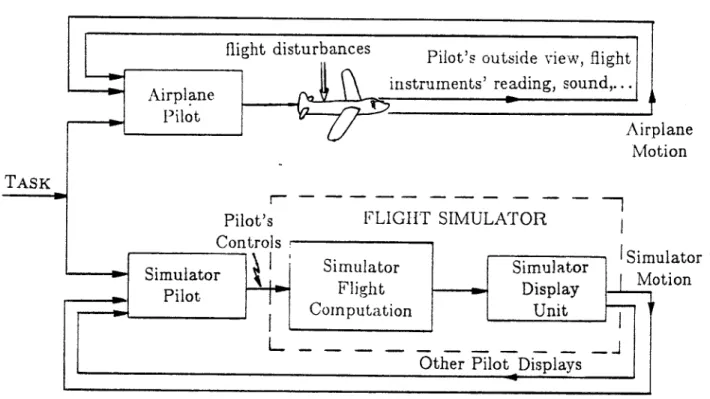
A ground based motion flight simulator is an airplane cockpit installed on a
motion system which has a certain motion capability. The purpose of the motion in the simulator is to provide the pilot who "flies" the simulator with motion cues which will aid in development of pilot control techniques and in assessment of simulated aircraft systems. The simulator, being a ground installation is, of course, constrained to stay within some bounds. One has to generate the simulator motion,
on the basis of the actual airplane motion, so as to (i) give relevant motion cues to
I I I 1 1 I 1
20 Introduction _
the pilot, and (ii) stay within the simulator constraints. The system which generates the motion commands for the simulator typically consists of a washout filter as well as limiting and transformation functions. In this thesis we define a new term,
washout system, which includes all these elements: WASHOUT SYSTEM
That part of the simulator display unit which computes the simulator motion-base commands on the basis of the computed airplane motions, so as not to exceed the motion-base constraints, yet retain the simulation flight
''realism" as best as possible.
2. Survey of Moving Base Flight Simulator Types
Several motion-base types are described below. These include variable stability airplanes which are used when ground base installation does not suffice. In Figure 1 we show the naming convention of the six degrees-of-freedom of a flight simulator:
1. Surge, fore-aft linear motion, x axis.
2. Sway, lateral linear motion, y axis.
3. Heave, vertical linear motion, z axis.
4. Roll, angular motion, 0 rotation.
5. Pitch, angular motion, 0 rotation.
6. Yaw, angular motion,
4'
rotation. 2.1. Cascaded systemsMany flight simulators use a cascaded motion system, that is, a cascade of six motion elements, one for each motion axis. The rotation is provided by a set of gimbals, one gimbal for each rotation axes. Thus, three nested gimbals are needed in order to have all three rotation axis. The rotation angle of each gimbal is given
by its corresponding Euler angle. Each gimbal is driven by a separate motor, and
the limitations of such a system are given in terms of the individual limits of each axis; the maximum Euler angles, Euler angular velocities and Euler angular accelerations.
The simulator linear motion is provided by a cascade of linear tracks, one for
each linear motion axis used, and the motion limitations are similar to those imposed
Survey of Io Ving Base Flight Simulator Types
21
for the gimbal- system. Usually these limitations also include a parabolic-limiter, which limits the motions to less than the maximum track length, such that the linear motion drive can stop the simulator cab before hitting the end stops (at the minimum and maximum linear travel limits). This type of limitation takes into consideration the current position and velocity of the simulator cab and the available motion drive power that can be used to stop the cab just short of the end stop. This limiter is called a parabolic-limiter since the position limit (where normal motion is stopped) is a parabolic function of the cab velocity. This type of limiter is also used for rotation motions produced by gimbal systems. These limiters are referenced in most descriptions of cascaded motion systems, such as the FSAA
flight simulator at NASA AMES [Sinacori77A] (Figure 2, 3). 2.2. Hexapod System
A much more complicated set of constraints on the simulator cab motion
capabilities, are inherent in the use of a "hexapod" moving base system, also called a "synergistic" (in Greek means work together) motion system. A synergistic motion simulator is one wherein the actuators must work in concert in order to display motion purely in a single degree-of-freedom. The hexapod is a very clever way of generating motion in six degrees-of-freedom, with very simple hardware. It was invented independently in 1965 by Peterson and Cappel, and is the most common flight simulator motion system today (Figure 4). Figures 5 is taken from Peterson's patent and describes the operation of the hexapod motion base. In principle six-degrees-of-freedom of motion are obtained by the six independent controls of the lengths' of the six legs of the motion base. The legs' lengths are
controlled by hydraulic pistons. It is clear that the limitations on the motion are
given in terms of the minimum and maximum leg lengths, their maximum rate of length change and maximum force capabilities. The maximum rate of length change is limited by the maximum hydraulic fluid flow rate, and the maximum force
is limited by the maximum fluid pressure. These limitations are fairly simple in the
hexapod coordinate system, but become very complicated when transformed to any of the other coordinate systems that are involved in the other parts of the flight simulation (e.g. the 'airplane equations of motion). The coordinate transformation
and an algorithm for real time calculation are discussed by Parrish [Dieudonne72]. In
I I I I 1 I
22 Introduction
this thesis, the problems involved in using such complicated motion limitations are considered in Chapter f and in Chapter 1V using PLQ (Pseudo Linear Quadratic). The performance capabilities of the hexapod motion base system at NASA Langley are shown in Table 1. In the Vertical Motion Simulator (VMS), at NASA AMES Research Center, a hexapod is used to provide the three rotation motions instead of a gimbal system (Figure 6).
2.3. Articulated Beam System
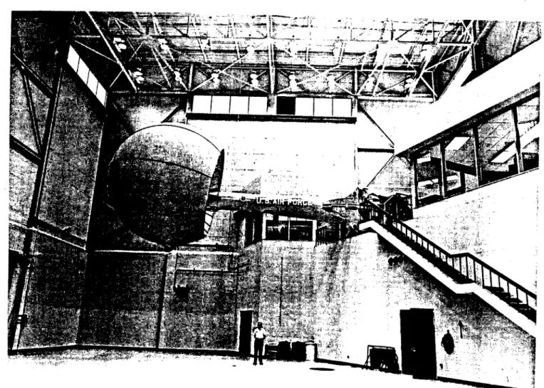
An interesting type of motion system is the articulated beam, or boom type, research motion base manufactured by Northrop. Figure 7 shows the one used at
Wright-Patterson Air Force Base. It is named "LAMARS" for Large Amplitude
Multi-mode Aerospace Research Simulator. It is a five degree of freedom motion system which consists of a cab inside a sphere (six meters in diameter), that is hinged on the end of a 10 meter beam. The cab is gimbaled so that it can pitch, roll and yaw with respect to the beam. The beam itself can move in a vertical, and in a horizontal plane. The degree of synergy is limited to the interaction between yaw and horizontal beam travel; pitch and vertical beam travel-for lateral and heave motions respectively. The motion limitations of this system are naturally given by the hydraulic actuators limitations that drive the motion system. A summary of the performance of this system is given in Table 1.
2.4. Centrifuge Motion System
All the above motion systems cannot provide a sustained acceleration beyond
half a g unit (5 m/sec2). Therefore centrifuge motion base systems were designed (Figure 8). These simulators consist of a gimbaled capsule mounted on the end of a long arm that rotates at high angular velocities (30 rpm and accelerations up to 10 rad/sec2). Common linear accelerations values obtained are up to 40 g (with human subjects the accelerations are limited to lower values). The design of a washout system for such a motion system involves further complications due to the rotating environment the pilot is in, and is not discussed in this thesis.
2.5. In-Flight Simulators, T-33 and TIFS
In Figure 9 we show two variable stability airplanes which are used as a flying
Survey of Moving Base Flight Simulator Types
airplane, the evaluation pilot is, of course, in an aircraft in flight. This sense
of actually being in an aircraft improves the simulation. Also, all the degrees of
freedom of an aircraft are present, and the motions duplication in the simulator can
be done quite well. One can see in Figure 9 that the "Total In-Flight Simulator"
(TIFS) has two cockpits one in front for the test pilot and one on top further back
for the safety pilot. Furthermore there are vertical aerodynamic surfaces attached
to the two ends of the wing in order to aid the simulation of side (sway) forces.
The longitudinal characteristics normally consist of two oscillatory modes,
short period and phugoid. In the T-33, the short-period natural frequency can
be varied from approximately 1.5 Hz to values less than zero (sic). The phugoid
natural frequency can be varied from approximately 0.05 Hz to values less than
zero (sic). The pilot control forces are obtained through feel servos and thus their
stick force per stick displacement can be varied. Both the natural frequency and
the damping of the Dutch roll mode can be varied from 1.0 Hz to less than zero
(sic) and damping ratio from 1.0 to 2.0. Other parameters can also be changed.
I I I II I 24 Introductioni 00C~o 0 0 0 0 0000 Heave Roll Swfay yaw Surge Pitch
Figure 1. The six degrees-of-freedom of a flight simulator (A Redifon suspended 6 degree-of-freedom motion platform) [Martin80.
COCKPIT DISPLAY 1OBSERVATION
ACCESS PLATFORM ROOM
VISUAL DISPLAY ENCLOSURE GIMBAL CENTER LOADING COCKPTCONTROL ROOM LONGITUDINAL (X)AXIS ROLL AXS LATERAL DRIVE TRATOR AND PIT
VERTICAL - Z)AXIS-- LATERAL CABLE MYAXIS CARRIER POWER CABLES EQUILIRATOR PIT EQUILIBRATORS
Survey of Moving Base Flight Simulator Types
Figure 3. Showing the lateral travel of the FSAA 6 degree-of-freedom motion platform [Martin80].
I I
26 Introduction
I
Figure 4. Link hexapod 6 degree-of-freedom motion platform. A typical "6-post" configuration [Martin8O].
.2
Survey on Moving Base Flight Sirmiutitor Types
N.Y. 29, 1966
?Ued March2 2. MFIG- 4
FIG. 7
FIG.
10
I. ft. PTR*SON YWTA3LA aND nDATALBL TO?FIG.
5
FIG.
8
FIG.
8
Figure 5. Positions of a hexapod motion base. From Peterson's patent diagrams [Puig78}.
FIG.
6
FIG.
9
I|I |I I I
28 Introduiction
Figure
G.
Vertical Motion Simulator (VMS) at NASA AMES Research Center [Jones8OI. AXIS DISPL RATE30 20 y 20 10 32 24 25 2 16 25' 15 50 - 22' 15 50 29' 15 50
ALL NUMBERS AND -UNITS: FT DEG. SEC. MOTION PERFORMANCE OF VMS
*MAXIMUM INDEPENDENT
Survey of Moving Base Flight Simulator Types
I
Figure 7. LAMARS 5 degree-of-freedom beam type motion platform [FCDL80.
Figure 8. Artist's conception of the modified naval human centrifuge [Von-Gierke61J.
I I i 1 1 1
30 Itroduction
-T.33 IN. GHT &lM'ULATOA otol oc!
Or" -- - -. rl_
for-"000 4
pI,Il a*0-37793'
TOTAL IN-FLIGHT SIMULATOR
Survey
of
Movfig Base Flight Simulator TypesMATCH JIDEALI
I7L~
PROPORTIONAL
CLIPPED AMPLITUDEI
CLIPPED ISLOPEI
MIXTURES CLIPPED AMPLITUDE & SLOPEI
TRANSFER FUNCTION IMANY EORMSI
JZL~
L
'
o
Figure 10. Characteristic response of several washout filter types (adapted from [Puig78]).
AF
~c~
Qs v %&4Z)-4 /1 EXCURSION HEAVE (FT) ± 0.33 ±30 ± 5. ± 2.8 ± 4.9 ± 10. LATERAL (FT) - ±2.0 50. 2.8 ± 6.0 ± 10. SURGE (FT) - t2.5 ± 4. ± 2.8 2.9 -ROLL (DEG) ± 11.5 2.2 ± 45. ± 20. ± 19. ± 25. PITCH (DEG) ± 11.5 ±25 ± 22. ± 25. ± 28. ± 25. YAW (DEG) 11.5 29 ±3 ±. ± o20. ±13. ±25. VELOCITY R4EAVE (FT/SEC) ± 2.3 2 0 8.6 ± 2.0 ± 2.5 ± 13. LATERAL (FT/SEC) - 10 ± 17.0 ± 2.0 ± 2.5 ± 10. SURGE (FT/SEC) - 2 6.3 2.0 ± 2.5 -ROLL (DEG/SEC ± 25.8 :t15 ±101.0 ± 20.0 ± 12. ± 60. PITCH (DEG/SEC) ± 25.8 4 15 ± 49.9 ± 20.0 ± 17. ± 60. YAW (DEG/SEC) ± 25.8 15 ± 40.0 ± 20.0 1± 11. ± 504 ACCELERATION HEAVE LATERAL SURGE ROLL PITCH YAW (GS) (GS) (GS) (DEG/S/S) (DEG/S/S) (DEG/S/S) 0.5 57.3 57.3 57.3 0.75' 0.5 50 50 50 0.37 0.37 0.31 229. 115. 115. 0.8 0.6 0.6 60. 60. 60. .75 .25 .59 80. 80.80.
3.0 1.6 460. 400. 200.Table 1. Comparison of motion platform operating envelopes [Martin80]
161
1.2
2- 6
|
I I II
32 Introduction
3. Survey of Present Washout Filters
Currently only washout systems that do not include the limiting logic, the axis transformation and the control system for the motion-base are used. In this case the washout system is termed a washout filter. In simple cases the washout filter can degenerate to just a constant gain. The following concepts are used in the design of washout filters i.e. the transformation between the computed airplane motion and the simulator motion (the first six are quoted from [Puig78]):
1. Memoryless, linear (1.1-1.2) and nonlinear (1.3-1.5):
1.1. The aircraft acceleration concept-The magnitude of the motion
system acceleration is equal to the magnitude of the aircraft acceleration; ideal, wishful case.
1.2. The proportional concept-The magnitude of the motion system acceleration is always proportional to the magnitude of the aircraft acceleration.
1.3. The clipped magnitude concept-The slope of the motion system
acceleration cannot exceed a set limit.
1.4. The clipped slope concept-The slope of the magnitude of the motion system acceleration cannot exceed a set limit.
1.5. The mixed concept-Any combination of the concepts, 2, 3, 4
above.
These concepts are also applied to velocity and position variable as well as acceleration. An example of concept 1.2 is the pitch and roll motions
on the Link GAT-1; the simulator pitch angle is 1/2 of the computed
pitch angle and the simulator roll is similarly 1/6. Figure 10 depicts these general washout categories.
2. Linear time-invariant system referenced as a "transfer function onset and washout concept' -The magnitude of the motion system acceleration and phase is determined by shaping filter techniques, i.e., aircraft acceleration subjected to a predetermined transfer function" [Puig78]. The filters
used are up to 41k order low pass, band pass and high pass filters.
Based on experience a set of design rules was put together by Sinacori [Sinacori77S]. An extensive effort to define a cost function and us it
to optimize the parameters of the washout filter for the LAMARS is
presented in [Hofman79]. Hosman further elaborated by optimizing the washout parameters using also a vestibular model. A comparison study
'A washout concept is defined as the methodology in determining the motion of the simulator
cockpit in order to washout the results of the onset cue, i.e., the velocity and position change, at subthreshold levels to allow the motion system to either return to the neutral position or a position such that the gravity vector is substituted for sustained linear acceleration (gravity align or g-tilt)
1Basic Approach
33
of several washout filter implementations was done recently by Michaeli
[Michaeli8I].
3. Adaptive washout filter (nonlinear system)on--line optimization of the
parameters of a linear washout [Parrish73].
4. LQ optimal washout filters-Linear system based on a Quadratic cost function which is designed using LQ optimal control [Kurosaki78],
[Sturgeon81], [Sivan82].
In this method the structure of the optimal washout is fond, based on the assumptions made in the problem formulation. The current work of this thesis is based on this concept but it also usesvestibular model in the formulation of the cost function [Sivan82].
5. Nonlinear optimal washout filters-Nonlinear system design based on
quadratic or "higher" than quadratic cost function (not using any model for the pilot). One design was done Friedland et. al. and is based on approximation to optimal control [Friedland66], [Friedland68],
[Friedland70], [Friedland73l. Another conceptual design example was
derived by Kosut [Kosut79] assuming a linear plant but a quartic cost function which leads to a nonlinear washout filter.
6. Washout system-A washout filter combined with the control system for
the motion-base. A model following structured system was suggested by Sturgeon
[Sturgeon8l].
In this thesis an optimal washout system(Ows)
concept is discussed in Chapter V. In our Ows implementation we also include the axis transformations.
4. Basic Approach
An abstract simulator design problem is formulated as follows: Given a dynamic system, S', called the actual system and another dynamic system, S', called a
simulator for Sa, and given a function which drives the system S', the problem is to find an operator, properly constrained, which will generate the input to S1 on the basis of the input to S', such that the discrepancy between the outputs of
Sa and S' will be as small as possible. This abstract simulator design problem is formulated as an optimal control problem and in the linear-quadratic case presented in Chapter _111 this problem is decomposed into two separately solvable subproblems:
(i) deterministic and (ii) stochastic. Both subproblems are solved; the stochastic
one for the Gaussian case only. An examination of the properties of the solution puts in evidence a parallel decomposition theorem and provides an interpretation of the dependence of the simulator design on the given parameters. These and other properties simplify the solution enabling its extension to include several nonlinear
effects developed in Chapter rv and Chapter V.
I I
34 Introduction T
The study of the nonlinear effects in Chapter
v_
includes three topics. The first topic is an extension of the deterministic-stochastic decomposition to include nonlinear dynamic system equations using a quadratic cost function. This decomposition shows a general method of how to separate and then combine the "open-loop" (deterministic) and the "closed-loop" (stochastic) solutions for the abstract simulator design problem.The second topic is the development of a Pseudo Linear Quadratic controller
(PLQ) for linear and nonlinear dynamic systems. The PLQ controller is derived
from the standard Linear Quadratic (LQ) optimal control solution by solving for a quasi-quadratic cost and a quasi-linear system for each value of the state. This results in a feedback with a leading linear term, i.e. using feedback gains that are functions of the system state rather than constants. Though PLQ is not a solution to any known formulated optimization it is an extension of the standard
LQ control. Furthermore, in the cases tested it has properties that match those
of known optimal nonlinear controllers derived for linear dynamic systems using a nonquadratic cost. On the other hand, PLQ is easier to compute and easier to implement, due to its "linear" form. Many of the PLQ properties still need to be developed including conditions for global stability for the multi dimension dynamic system case. It is expected that the resulting PLQ controller would show similar robustness properties as the LQ controller.
The third nonlinear effect discussed is a sign sensitive cost formulation and solution. The cost function is put into a form that includes a correlation function term that is evaluated between the outputs of the systems S' and S'. It is shown that any antisymmetric compressive memoryless output function cascaded to the linear dynamics of both S' and S' leads to a cost function that includes a sign
sensitive term. This problem is put into a LQ form which no longer has a positive
definite cost. It is shown that a unique solution exists for the abstract simulator design problem. Putting all these elements together enables one to develop a methodology for the design of abstract optimal simulators.
Next, the solution and properties of the abstract simulator problem are
applied to the design of motion generation for moving-base flight simulators. The
Basic Approach
35
formulation and approximation processes used to fit the flight simulator motion problem into the form of the general abstract simulator problem are discussed in Chapter i. 'The optimization criterion selected is a quadratic norm of the difference between the physiological outputs of the vestibular organs of a pilot in an imaginary reference airplane and those of a pilot in the simulator. In the design of the motion for a flight simulator vestibular models based on physiological and psychophysical experiments are used. This includes consideration of vestibular sensor saturation and the multiplicative nature of physiological noise in the nervous system. This latter is modeled by an antisymmetric compressive memoryless output nonlinearity (in Chapter l_). The LQ abstract simulator properties imply a 2-2-1-1 physical axis decoupling theorem for the feedback gains, i.e. Pitch-Surge, Roll-Sway, Yaw, Heave axis group decoupling. The 2 axis coupling is due to gravity. This 2-2-1-1 rule is well known to designers of simulator motion systems. What is usually overlooked, however, is that the feed-forward gains do not decouple the same way due to the effect of the airplane dynamics coupling (Chapter M1). Axis transformations are included in the motion system implementation in Chapter VI. In this case coupling between all six physical axes is obtained, a property not existing in current designs. Using a similar method we also include head rotations by considering a head axis system for each pilot, airplane and simulator (Chapter U.9.4 and Chapter M1), which should further improve the simulator motion sensation.
Putting all these elements together we obtain a new design methodology for the design of motion for moving-base flight simulators. This design methodology is demonstrated by several design examples that are solved and simulated in Chapter V. The examples and solution properties conform to the set of empirical design rules used by experienced engineers to determine: the structure (2-2-1-1 theorem), the initial setting of the pole locations; the expected lower motion fidelity as the poles' frequency increases; and the cross coupling gain between the linear and rotation motion input (called g tilt) used in flight simulator motion generation systems.
Finally the design method was implemented and tested by twenty pilots
using several experiments (Chapter _-11). These designs were implemented for the
pitch and surge axes on a Lin-k GAT-1 General Aviation flight simulator Trainer.
I I
36 Introduction
These tests confirm the suggested design method, including equal weighting of the normalized vestibular linear and rotation components. in this system, a PLQ (Pseudo Linear Quadratic, developed in Chapter W) was used to build a nonlinear-motion-generation system for the Link GAT-1 simulator that better accounts for
the hard limits of the pitch motion.
5. What to Read in order to Design an Optimal Washout System
First read the following:
(i) Summary-over view of the whole thesis.
(ii) Chapter VIII, Section 1-elements in the design of an Optimal Washout
System (Ows).
(iii) Chapter 1, introduction and Sections: 1-what is the definition of the
problem, 4-basic approach used.
(iv) Chapter fl, Section 1, paragraph 1-washout system definition. (v) Chapter FI, Figure 1--main approach used here.
(vi) Chapter FI, Section 2, paragraphs 1, 2 and last one (see Figure 3)-class of airplane motion definition.
(vii) Chapter ft, Section 5, paragraph 1-cost function.
(viii) Chapter FI, Section 6, paragraph 1, 2, 3, Figures 5 and 6-Optimal
Washout System
(Ows)
Design Problem, use of sensory comparison as performance criteria.(ix) Chapter FI, Section 6, last titled paragraph-optimization criteria. (x) Chapter FI, Subsection 9.1, 9.2 and 9.5-axis systems.
(xi) Chapter HI, introduction.
(xii) Chapter
Il,
Section 1-Linear Quadratic (LQ) problem statement.(xiii) Chapter i, Section 2 and Figure 1-deterministic-stochastic problem
separation.
(xiv) Chapter MY, introduction.
(xv) Chapter M, Subsection 2.3 example of PLQ (Pseudo Linear
Quadratic)-how to do a nonlinear design to better account for the finite limits of the
simulator motion.
What to Read in order to Design an Optimal Washout System
(xvi) Chapter V, introduction, Section 2 and 3-example of two-degree-of-freedom motion design. Study this example thoroughly.
(xvii) All Chapter V1, skip derivations in equations (18)-(25)-how to implement an Optimal Washout System
(Ows)
and take into account the nonlinearities due to axes transformations.(xviii) Chapter 71I, Figure 2-detailed example of Ows block diagram.
(xix) Chapter VII, use equations (1)-(6) for your vestibular model realization.
(xx) Chapter V-1, if your motion-base is unstable (with no control) read also Subsection 2.2 paragraph one before last and look at Figure 6-limiting logic for an unstable motion-base.
(xxi) Chapter MIII, introduction, Section 1-elements in the design of an Optimal Washout System (Ows).
(xxii) Chapter VIII, Section 2-conclusions from the use of an Ows with the Link GAT-1 three degree-of-freedom (rotations) flight simulator.
In the second reading also go over:
(i) Chapter 1, Section 2-modeling of the airplane anticipated motion. (ii) Chapter T, Section 5-cost function formulation.
(iii) Chapter H, end of Section 6 after Table 1-choice of sensory comparison for a performance index.
(iv) Chapter 1, Section 9-axes system and head motion consideration. (v) Chapter T, Section 10-abstract optimal simulator design problem
statement.
COO
References 39
References
[Dieudonne72] Dieudonne, J.E., Parrish, R.V. and Bardusch, R.E., "An Actuator
Extension Transformation for a Motion Simulator and an Inverse Transformation
Applying Newton-Raphson's Method," NASA Langley Research Center report TN D-7067, November, 1972.
[FCDL80] U.S. Air Force, "Flight Control Development Laboratory," Technical
Brochure, Air Force Flight Dynamics Laboratory, Wright-Patterson Air Force Base,
Ohio.
[Friedland66] Friedland, B., Thau, F.E., Cohen, V.D., and Ellis, J., "Study of Quasi-Optimum Feedback Control Techniques," NASA Report CR-527, AMES
Research Center, Aug., 1966.
[Friedland68] Friedland, B., Thau, F.E., Welt, S., Ling, C.K., and Schilder, M.,
"Additional Studies of Quasi-Optimum Feedback Control Techniques," NASA Technical Report CR-1099, AMES Research Center, July, 1968.
[Friedland70] Friedland, B. and Ling, C.K., "Quasi-Optimum Design of Control Systems for Moving-Base Simulators," NASA Report CR-1614, AMES Research Center, Oct., 1970.
[Friedland73] Friedland, B., Ling, C.K. and Hutton, M.F., "Quasi-Optimum Design
of a six Degree of Freedom Moving-Base Simulator," NASA Report CR-2312,
AMES Research Center, Oct., 1973.
[Hofman79] Hofman, L.G. and Riedel, S.A., "Manned Engineering Flight Simulation Validation, part I: Simulation Requirements and Simulator Motion System Performance," Systems Technology ,Inc., AFFDL-TR-78-192, Feb., 1979.
[Hosman79] Hosman, R.J.A.W., van der Vaart, J.C. and van de Moesdijk, G.A.J., "Optimalization and Evaluation of Linear Motion Filters," Annual Conference
on Manual Control, March, 1979.
[Jones80] Jones, A.D., "OPerations Manual: Vertical Motion Simulator (VMS) S.08," NASA Technical Memorandum 81180, May, 1980.
[Kosut79] Kosut, R.L., "Nonlinear Optimal Cue-Shaping Filters for Motion Base Simulators," Journal of Guidance and Control, 2, pp. 486-490, Dec., 1979. [Kurosaki78] Kurosaki, M. "Optimal Washout for Control of a Moving Base Simulator," Proceeding of the Seventh Triennal World Congress of Ffac, Helsinki, Finland, 2, pp. 1311-1318, June, 1978.
[Martin80] Martin, E.A., "Motion and Force Simulation Systems," Simulator Course at Wright-Patterson Air Force Base, Ohio, 1980.
[Michaeli8l] Michaeli, S., "Principles and Realizations of the Drive-Logic in
Flight-Simulators," M.Sc. Final Paper, Technion-Israel Institute of Technology, Haifa,
Israel, July, 1981.
[Parrish73] Parrish, R.V., Dieudonne, J.E., Bowles, R.L. and Martin, Jr. D.J.,,
"Coordinated adaptive Washout for Motion Simulators," presented at AIAA
I I
![Figure 2. Schematic arrangement of the FSAA flight simulator motion system [Sinacori77A].](https://thumb-eu.123doks.com/thumbv2/123doknet/14687877.560584/25.918.147.802.604.1043/figure-schematic-arrangement-fsaa-flight-simulator-motion-sinacori.webp)
![Figure 3. Showing the lateral travel of the FSAA 6 degree-of-freedom motion platform [Martin80].](https://thumb-eu.123doks.com/thumbv2/123doknet/14687877.560584/26.918.159.822.133.981/figure-showing-lateral-travel-degree-freedom-platform-martin.webp)
![Figure 4. Link hexapod 6 degree-of-freedom motion platform. A typical "6-post" configuration [Martin8O].](https://thumb-eu.123doks.com/thumbv2/123doknet/14687877.560584/27.918.99.796.148.967/figure-hexapod-degree-freedom-platform-typical-configuration-martin.webp)

![Figure 9. In-Flight Simulators, T-33 and TIFS [FCDL80].](https://thumb-eu.123doks.com/thumbv2/123doknet/14687877.560584/31.918.77.810.100.1052/figure-flight-simulators-t-tifs-fcdl.webp)
![Figure 10. Characteristic response of several washout filter types (adapted from [Puig78]).](https://thumb-eu.123doks.com/thumbv2/123doknet/14687877.560584/32.918.267.669.134.417/figure-characteristic-response-washout-filter-types-adapted-puig.webp)