HAL Id: hal-01812215
https://hal-univ-rennes1.archives-ouvertes.fr/hal-01812215
Submitted on 19 Jun 2018
HAL is a multi-disciplinary open access
archive for the deposit and dissemination of
sci-entific research documents, whether they are
pub-lished or not. The documents may come from
teaching and research institutions in France or
abroad, or from public or private research centers.
L’archive ouverte pluridisciplinaire HAL, est
destinée au dépôt et à la diffusion de documents
scientifiques de niveau recherche, publiés ou non,
émanant des établissements d’enseignement et de
recherche français ou étrangers, des laboratoires
publics ou privés.
A hybrid image fusion system for endovascular
interventions of peripheral artery disease
Florent Lalys, Ketty Favre, Alexandre Villena, Vincent Durrmann, Mathieu
Colleaux, Antoine Lucas, Adrien Kaladji
To cite this version:
Florent Lalys, Ketty Favre, Alexandre Villena, Vincent Durrmann, Mathieu Colleaux, et al.. A
hybrid image fusion system for endovascular interventions of peripheral artery disease. International
Journal of Computer Assisted Radiology and Surgery, Springer Verlag, 2018, 13 (7), pp.997-1007.
�10.1007/s11548-018-1731-9�. �hal-01812215�
A hybrid image fusion system for endovascular interventions of peripheral
artery disease
Florent Lalys 1, Ketty Favre1, Alexandre Villena 2, Vincent Durrmann 1, Mathieu Colleaux 1, Antoine Lucas 2,3,4, Adrien Kaladji 2,3,4
1. Therenva, F-35000, Rennes, France
2. CHU Rennes, Department of Cardiothoracic and Vascular Surgery, F-35033 Rennes, France 3. INSERM, U1099, F-35000 Rennes, France
4. University Rennes 1, Signal and Image Processing Laboratory (LTSI), F-35000 Rennes, France
Abstract
Purpose. Interventional endovascular treatment has become the first line of management in the treatment of
peripheral artery disease (PAD). However, contrast and radiation exposure continue to limit the feasibility of these procedures. This paper presents a novel hybrid image fusion system for endovascular intervention of PAD. We present two different roadmapping methods from intra- and pre-interventional imaging that can be used ei-ther simultaneously or independently, constituting the navigation system.
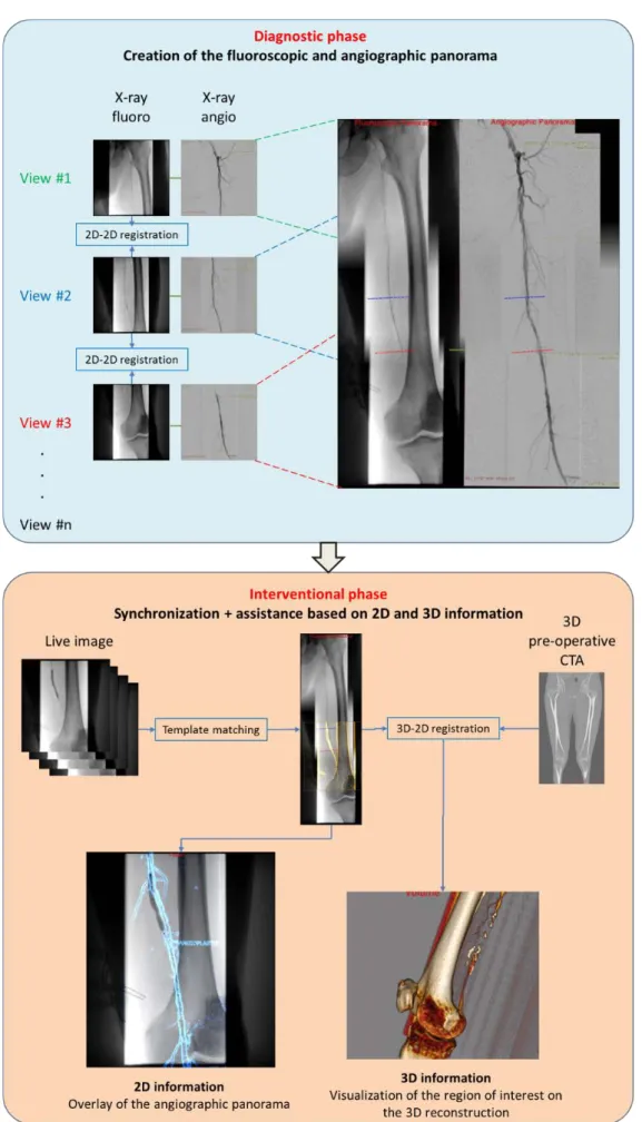
Methods. The navigation system is decomposed into several steps that can be entirely integrated within the
pro-cedure workflow without modifying it to benefit from the roadmapping. First, a 2D panorama of the entire pe-ripheral artery system is automatically created based on a sequence of stepping fluoroscopic images acquired during the intra-interventional diagnosis phase. During the interventional phase, the live image can be synchro-nized on the panorama to form the basis of the image fusion system. Two types of augmented information are then integrated. First, an angiography panorama is proposed to avoid contrast media re-injection. Information exploiting the pre-interventional computed tomography angiography (CTA) is also brought to the surgeon by means of semi-automatic 3D/2D registration on the 2D panorama. Each step of the workflow was independently validated.
Results. Experiments for both the 2D panorama creation and the synchronization processes showed very
accu-rate results (errors of 1.24 mm and 2.6 +/- 1.4 mm, respectively), similarly to the registration on the 3D CTA (errors of 1.5 +/- 0.7 mm), with minimal user interaction and very low computation time. First results of an on-going clinical study highlighted its major clinical added-value on intra-operative parameters.
Conclusions. No image fusion system has been proposed yet for endovascular procedures of PAD in lower
ex-tremities. More globally, such a navigation system, combining image fusion from different 2D and 3D image sources, is novel in the field of endovascular procedures.
Keywords: Image fusion; endovascular procedures; peripheral artery disease; lower extremities Corresponding author: Florent Lalys, email: [email protected]. Tel : +33789833846
1
Introduction
Peripheral artery disease (PAD) results from the build-up of plaque in the arteries of the legs. This plaque can partially obstruct the artery and is called a stenosis or a thrombosis when the artery is fully clogged. The diagno-sis is usually made using duplex ultrasound, CT angiography (CTA) or MR angiography. Interventional endo-vascular treatment, whenever feasible, has become the first line of management in the treatment of PAD, pro-gressively replacing surgery [1]. Endovascular treatment offers a lower risk alternative to open surgery in many patients with multiple comorbidities, including ischemia. The endovascular methods for revascularization mainly include percutaneous transluminal balloon angioplasty (PTA) and stenting.
Use of duplex ultrasound is the most common approach for assessing the hemodynamic behavior of lesions, though in some cases CTA is performed. Indeed, interventions are in most cases arteriography in intent to treat, i.e. an arteriography of the femoro-popliteal artery is done in order to identify lesions before treatment. This phase, performed in the operating room, can be seen as the diagnosis phase. Conventional X-ray equipment can only provide a limited field-of-view, and all lesions cannot be visualized entirely on a single angiography. In clinical routine, information about lesions are obtained at the beginning of the intervention by stepping the C-arm and/or the table sequentially to different locations. In a second phase, each lesion is independently treated. However, moving the C-arm to treat stepped lesions or long occlusions results in a loss of the arterial mask and therefore requires multiple angiographies that have the effect of increasing the volume of iodinated contrast agent injected, increasing the irradiation of the patient and the surgical staff. Reducing the amount of contrast media is of importance because of its potentially nephrotoxic effects in patient with renal failure [2]. In addition, this projective imaging modality inevitably leads to topographic errors and gives no information on arterial wall quality. Therefore, additional information from pre-interventional and intra-interventional images is needed to gain precision during endovascular tools use and to help visualizing target vessels.
In the context of endovascular procedures, image fusion techniques mainly focused on the use of rotational C-arms in hybrid OR, the aim becoming to enrich the intraoperative images by projecting the preoperative image [3]. Using a mobile C-arm, very few works have been reported in the context of endovascular procedures [4, 5], all focusing on abdominal aortic aneurysms. In the specific context of PAD for lower extremities, preliminary work has been reported by Sailer et al. [6] with fusion of pre-interventional MRA and CTA datasets with live fluoroscopy. However, the system is designed to work only in hybrid OR. While some studies focused on carotid arteries in swine models [7, 8], no fusion system has been proposed yet for PAD procedures of lower extremities in conventional OR. The main idea of our hybrid navigation system is to fully exploit 2D and 3D images ac-quired during the perioperative clinical workflow. The term hybrid is employed here to refer to the use of both sources of data either simultaneously or independently.
2
Methods
The proposed navigation system is decomposed into several steps that are entirely integrated within the clinical workflow and that will be independently presented and validated. The overall workflow is depicted in Fig. 1. First, the sequence of fluoroscopic images captured during the diagnosis phase is combined to create a fluoro-scopic panorama, used as a reference image along the intervention (subsection 2.1). Then, during the interven-tional phase, the live fluoroscopic image can be superimposed on the panorama using an automatic registration approach (subsection 2.2). These two steps form the basis of our image fusion navigation system. An angi-ography panorama, constructed during the diagnosis phase, is used together with the fluoroscopic panorama to extract information about the treated lesion (subsection 2.3). Information exploiting the pre-interventional CTA, such as the arterial wall quality and plaques, is also brought to the surgeon by means of semi-automatic 3D/2D registration (subsection 2.4). Finally, first results of an on-going clinical study are shown in subsection 2.5 to highlight the major clinical added-value.
2.1 Creation of the fluoroscopic panorama
During the diagnosis phase, a panorama can be formed from successive digital images. The creation of the pano-rama is presented in the following subsections.
2.1.1 State-of-the-art
Image stitching has gained much interest for X-ray images due to the limited field-of-view, the noise present in images and the fact that relevant structures can be missing in overlapping areas. To propose an alternative solu-tion to hybrid ORs with robotized/fully automatic solusolu-tions, which are not accessible in every clinical center, automatic or semi-automatic image-based methods compatible with mobile C-arms in conventional ORs are required [5–16].
In the category of feature-based methods, Paudel et al.[21] used SIFT, SURF and Harris keypoints to stitch chest X-ray images, taking advantage of the amount of strong features present on chest images. Other methods em-ployed additional radio-opaque materials. Yaniv and Joskowicz [16] created long bone panorama from fluoro-scopic X-ray images using a ruler alongside the long bone, similarly to Chen et al. [20]. Another similar method employed an absolute reference panel with coordinates places under the bones [18]. Goossen et al. [9] presented an automatic algorithm based on a ruler to perform the first feature-based registration, which is followed by a content-based registration to match anatomy. Wang et al. [17, 19] proposed a parallax-free panoramic X-ray image that preserves the linear perspective projection property. They made use of a visual marker pattern along with a camera augmented mobile C-arm. If feature-based methods present some advantages, it requires supple-mentary materials for extracting relevant visual features from the scene.
To overcome the drawback of feature-based methods, Kumar et al. [12] proposed a method for stitching hand X-ray images using histogram matching and mutual information. Samsudin et al. [10] utilizes minimum average correlation energy filters to merge hand X-ray image pairs. With chest X-ray images, Vela et al. [14] used image stitching with classical sum-of-square difference, while Yang et al. [13] proposed an automated image stitching method using an improved phase correlation algorithm. Finally, using lower limb X-ray images, Capek et al. [11] utilized a point matching method together with the normalized correlation coefficient (NCC) to evaluate a similarity measure (SM) of the X-ray image. The survey from the prior art shows that panorama creation from X-ray images has focused on orthopedics applications. Moreover, there is still no study focusing on the best SM to be used, and proposing a complete validation scheme.
2.1.2 Image stitching
The objective was to register 2D fluoroscopic images with limited overlapping portions to find the best match in each adjacent pair. The minimal overlap ratio needed between image pair was set to 20%. The problem was ex-pressed as a succession of 2D rigid registration problems, with two translation parameters and potential slight in-plane rotations induced by the position of the C-arm. The main challenges are the limited overlapping areas, and the lack of strong features in lower limb images. To reduce calculation time, a multi-resolution scheme with progressive refinement was proposed with multiple optimization phases from coarse to fine levels.
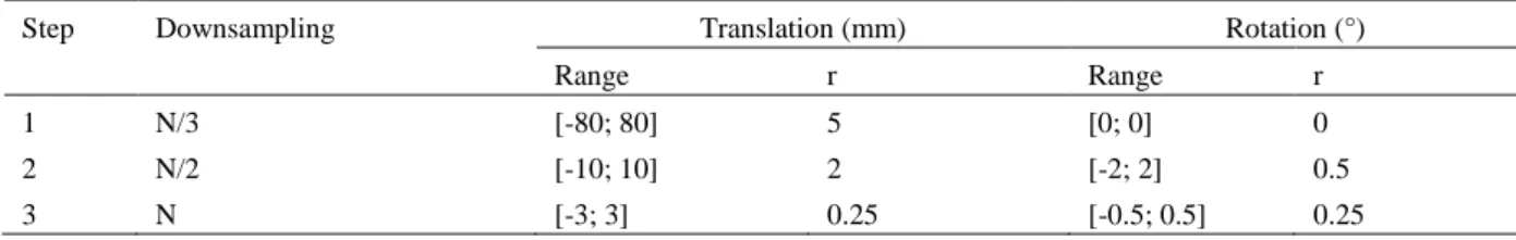
Tab. 1. Parameters used during the optimization phases of the panorama creation (N = total number of pixels contained in the
region of interest in the intra-interventional image, r = resolution of the discretized range of the parameters). Step Downsampling Translation (mm) Rotation (°)
Range r Range r
1 N/3 [-80; 80] 5 [0; 0] 0
2 N/2 [-10; 10] 2 [-2; 2] 0.5
During each phase, a reduced exhaustive search is performed by decomposing the transformations. An optimiza-tion by exhaustive search consists in sampling the parameter space of the transformaoptimiza-tion, and calculating a SM for each combination of parameters to finally keep the combination of parameters with the best SM. The ob-tained parameters are used as the initial solution for the next resolution level. The center of rotation was defined as the center of the image. The registration method finally relies on three optimization phases (Table .1).
SM can be divided into two main categories, the global similarity and the local similarity measures. Generally, it has been shown that the local SMs present good accuracy but a narrow capture range, and conversely for the global SMs [22, 23]. Based on the literature review on image stitching using X-ray images, we applied the proto-col to four global SMs (Sum of Square Difference (SSD), mutual information (MI), entropy correlation coeffi-cient (ECC), normalized cross-correlation (NCC)) and two local SMs (the gradient difference (GD) and the gra-dient information (GI)). GI has been previously used for 3D/2D registration between CTA and X-ray image with great success [5]. As global SM generally don’t contain spatial information, combination of global and local SM were also tested [24].
As the performance of a registration method is mainly influenced by SMs [25], we followed the evaluation pro-tocol proposed by Skerl et al. [26] to assess their robustness. The propro-tocol evaluates the criteria along N random-ly oriented line segments (profiles) passing through the gold standard (GS) point in the K-dimensional parameter space. It generates M sampling points equally distributed on each line. Sampling points lie inside of a hy-persphere of radius R in the parametric space. Several measures of the criterion performance can be calculated, among which the accuracy (ACC), the distinctiveness of the optimum (DO), the number of minima (NOM), the capture range (CR) and the risk of non-convergence (RON). The measures of the properties stabilize when using ~50 profiles
2.1.3 Seamless blending
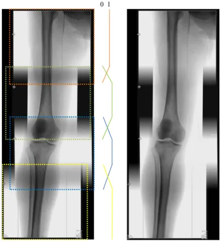
The seam between the stitched images should be invisible for visualization purposes first, but especially to have a smooth image to be used for the synchronization step. To remove the seam on the panoramic view and avoid unwanted image gradients, we used a triangulation averaging algorithm [12]. Triangulation averaging is applied on the overlapped area of the images, with linearly decreasing values in the overlapping range, as shown in Fig. 2. The seamless blending is only applied after a first verification step, where the user can adjust the result of the registration if necessary without any blending process.
Fig. 2. Fluoroscopic panorama without (left) and with (right) seamless blending.
2.2 Registration of the live fluoroscopy to the panorama
After the diagnosis phase, the surgeon successively acquires live fluoroscopic images to treat lesions from the most distal to the most proximal during the interventional phase. These successive images, sometimes with dif-ferent zoom levels, can be directly synchronized on the panorama similar to a template matching process. Com-pared to the rigid registration problem from subsection 2.1.2, the scale parameter is added to take into account potential C-arm zoom actions or table height changes. The minimal overlap ratio between the template and the panorama was set to 80%, assuming that all lesions treated during the interventional phase have been previously detected and located during the initial diagnosis phase.
2.3 Roadmapping using angiographic panorama
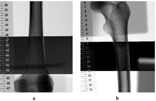
During the diagnosis phase, stepping angiographies are acquired along with fluoroscopic images. Relying on the spatial correspondence between angiography and fluoroscopy, and using the registration transformations com-puted for the fluoroscopic panorama, an angiographic panorama representing the arterial tree is created with similar blending process. With the live image being automatically synchronized on the fluoroscopic panorama, overlay of vascular structures on the live images is made available to the surgeon. Overlay of vascular structures on fluoroscopic image is of great interest for assisting the operator for catheterization or prosthesis deployment procedures. However, one major issue remains the parallax effect, which occurs when objects are not localized on the same plane. It is the case here, because the registration is performed using bones information, while useful information to be displayed is the arterial tree (e.g. femoral or popliteal arteries) from the angiographic panorama (Fig. 3.).
Fig. 3. Example of parallax effect using a bone phantom and a ruler. a) the ruler is positioned below the phantom.
b) the ruler is positioned at the same level.
2.4 Roadmapping using 3D pre-interventional CTA
Similarly to 2D/2D registration methods used in 2.1 and 2.2, 3D/2D registration methods are divided into fea-ture-based and intensity-based approaches. Intensity-based approaches do not require segmentation of particular structures, representing an advantage given the diversity of intra-interventional scenes. From the extended set of publications on 3D/2D registration methods, interest has been given to optimization methods
[27]
, to accelerate the generation of DRRs using CPU[28]
or GPU[29]
computing strategies or to automate the initialization[30]
. While extensive strategies have been proposed for many different fields, including radiotherapy[31]
or radio-surgery[32]
, only Penney et al.[4]
, Duménil et al.[5]
and Mitrovic et al.[33]
proposed registration strategies for endovascular procedures.Our 3D fusion system relies on previous work on an versatile rigid 3D/2D registration [5] and will not be de-tailed. The 3D CTA can be registered either directly to the final panorama or to a single fluoroscopic acquisition. The registration must be initialized with C-arm angulation and with a rough alignment of the bony structures. The iconic 3D/2D registration is then employed with a computation time that never exceeds 20s.
2.5 Clinical study – Proof of concept
Beyond the scientific challenges, the clinical benefits also need to be assessed. As part of an on-going clinical study, the registration capabilities were integrated into a prototype navigation system, which was routinely used during endovascular procedures of PAD for 22 patients using a Siemens Cios Alpha flat-panel detector. No 3D pre-interventional information was used for these procedures, only 2D roadmapping was tested. Intra-interventional information about the procedure were recorded following the clinical protocol, including total volume of contrast media injected to the patient, fluoroscopy time, dose area product (DAP), cumulative air kerma (CAK) and time of procedure. These measures were compared with a control group of 40 patients also recently operated for a PAD with the exact same flat panel detector and same operators. Non-parametric statisti-cal analysis was preferred for comparing means of both groups.
3
Experiments and results
3.1 Creation of the fluoroscopic panorama
The evaluation of the SMs was performed on a dataset of 30 patients, all treated for a PAD at the Rennes Uni-versity Hospital, France. Fifteen were operated in a conventional OR using a flat-panel detector (Cios Alpha, Siemens Healthcare), 10 with an X-ray image intensifier (OEC 9800, GE healthcare), and 5 in a hybrid OR (Ar-tis Zeego, Siemens Healthcare). From this dataset, a total of 65 pairs of X-ray fluoroscopic images were ac-quired. Images coming from the X-ray image intensifier were undistorted based on the OpenCV calibration pro-cedure using a beam stop phantom (QRM GmbH, Germany). As performed during clinical routine, all pairs of images were acquired using same table and C-arm configurations, including same C-arm orientations (0 CRA-CAU, 0 LAO-RAO for 62 out of 65 pairs), same C-arm field-of-view (large FOV) and same table height. These parameters are requirements that allow us to optimize only the two in-plane translations and the in-plan rotation. For each image pair, the GS was determined by a single expert and used as a reference for the evaluation proto-col. In addition, the intra-expert variability was estimated with three GS processes on the entire set of 65 image pairs. ACC, RON, NOM, CR and DO properties were evaluated on 10 SMs (SSD, ECC, MI, NCC, GD, GI, GDxMI, GDxNCC, GIxMI, GIxNCC) for the registration of the 65 fluoroscopic image pairs.
Fig. 4. Example of an optimization curve obtained using GI.
Overall, with ∂ = 1mm, MI, GI and the combination of GI and MI presents globally better performances than all the other SMs. Both MI and GI had complementary advantages, and the combination of both SMs can lead to a very robust and consistent SM, with all indicators showing great results (ACC = 1.24mm, CR = 1.68mm, DO(𝜕𝜕) = 0.41 𝑚𝑚𝑚𝑚−1,RON(𝜕𝜕) = 0.87 x10⁻³𝑚𝑚𝑚𝑚−1 , NOM(𝜕𝜕) = 1.4). This SM was conserved for the image stitching part.
Using MI x GI, only 5 registrations out of 65 image pairs showed registration errors higher than 5mm. For three of these failures the overlap ratio was very close to 20%, and no strong feature was present. The last two failures were explained by the presence of multiple tools and very poor contrast. The five failures were observed with images coming from the X-ray image intensifier (GE OEC device). The average computation time for one image pair was 0.8 s on a standard machine. Finally, the intra-expert variability showed a precision of 0.87 +/- 0.91 mm.
3.2 Synchronization of the current live image
In order to find the best synchronization algorithm, we tested the same similarity measures from the prior evalua-tion protocol. Only the average accuracy was considered for evaluating the different methods. The validaevalua-tion dataset was composed of 15 patients (5 operated with the Cios Alpha, 5 with the Artis Zeego and 5 with the GE OEC) for whom a complete fluoroscopic panorama composed of at least 3 images was automatically created and manually adjusted, if needed. From the 15 patients, a total of 80 live images acquired during the interventional phase (i.e. not employed for the panorama creation) were used for validating the synchronization process. From the 80 images, 32 were located at the level of the hip (with both landmarks from the hip and the femur), 28 at the level of femur (without any hip of knee landmarks) and 20 at the level of the knee (with femur and knee land-marks). Similarly to the panorama creation, the GS was determined by an expert and used as a reference for computing synchronization accuracies.
GI and GI x MI showed very good performances (accuracies of 2.8 +/- 1.9 mm and 2.6 +/- 1.4 mm, respectively), whereas other tested SMs showed limited performances with accuracies above 4mm. Overall, using the GI x MI SM, only 6 images failed to be located (showing an error > 5mm), 4 being images from the image intensifier. In addition, 6 other images needed to be slightlty manually corrected by less than 5mm. Aver-age processing time was 1.6 s on a standard machine.
3.3 Roadmapping using angiographic panorama
To estimate the parallax error, a dataset of 12 patients was used. Fluoroscopic panoramas were first created and manually validated, and ostia of collaterals were annotated by an expert on angiographic images. If the same landmark was annotated in different views, an Euclidean distance between both landmark positions can be calcu-lated on the angiographic panorama. In order to estimate errors with respect to the anatomical position of arteries and the bony structure, 3 anatomical zones were defined along the femoro-popliteal axis: the iliac, the femoral and the popliteal zones (Fig. 5.).
Estimated parallax errors showed large heterogeneity among anatomical zones. Errors were calculated as 1.2 mm +/- 0.4 mm, 1.9 .mm +/- 0.7 mm, and 4.2 mm +/- 1.1 mm for the iliac, the femoral and the popliteal stages re-spectively. These values are only suitable for this configuration without any C-arm angles, and with an overlap ratio of ~40%. Thanks to the prior synchronization, the surgeon can visualize vascular structures without addi-tional contrast media, either in overlay or directly with the corresponding ROI (Fig. 6).
3.4 Roadmapping with 3D information
To evaluate the algorithm for this specific application, a dataset of 12 patients was collected (all operated with the C-arm Cios Alpha). For each patient, a pre-interventional CT-scan with contrast injection was performed before the operation with a 64 slice CT-scan (LightSpeed16, GE Healthcare). Intra-operatively, a fluoroscopic panorama comprising at least 3 images was also automatically created (and manually adjusted, if needed). 100 registrations with random initial transformations were performed for each patient. The ranges of initial transfor-mations for each degree of freedom were estimated based on the manual registration initializations performed by 3 surgeons (one experienced and two residents) on 10 patients using our system. Registration error was comput-ed as the average distance between the projection of a set of 10 anatomical keypoints situatcomput-ed along the bony structures with the transformation obtained by registration and that performed with the reference transformation obtained by an expert.
Registration using the full leg panorama leads to more precise registration than when using a single fluoroscopic image only (1.5 +/- 0.7 mm Vs 2.4 +/- 1.2 mm, respectively). Registration showed high accuracy (average regis-tration error of 1.5 +/- 0.7mm) and did not appear to be disturbed by the presence of endovascular tools such as catheter, balloon, or rigid guidewire. Once registered, the corresponding ROI of the C-arm field-of-view can be made available to the surgeon (Fig. 6.), and qualitative information of the arterial wall quality, such as calcifica-tions or precise stenosis/thrombosis information are available. Those information are not available using the 2D angiographic panorama solely and are real added-value for the surgeon. The visualization of the lesion in 3D might also reduce the risk of under or over-estimation of the stenosis.
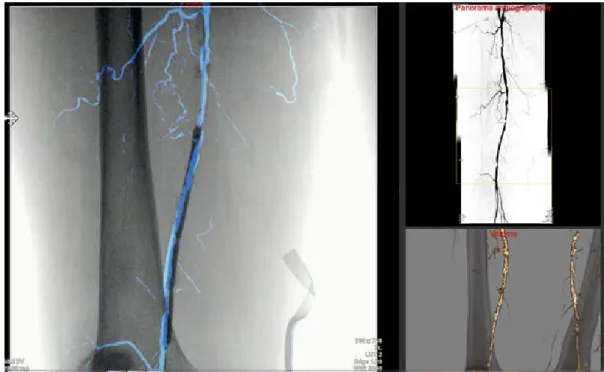
Fig. 5. Visualization of the navigation prototype UI. Left: overlay of the angiographic panorama on the live image. Upper
right: enhanced angiographic panorama, with the corresponding ROI. Bottom right: information from the pre-interventional CTA, where the ROI of the 3D volume corresponds to the ROI of the live acquisition.
3.5 Clinical added-value – Proof of concept
During all interventions, we observed that our approach was compatible with clinical workflow. First results of the clinical study showed a significant reduction for important intra-interventional parameters, including volume of contrast media injected to the patient and major irradiation parameters (DAP and CAK). Total fluoroscopy time and procedure time didn’t show any significant reduction (Tab. 2.).
Tab. 2. Comparison of intra-interventional parameters between the groups with/without 2D roadmapping.
4
Discussion
A complete image-guided system for endovascular procedures of PAD is presented in this paper, incorporating 3D and 2D information from pre-interventional and intra-interventional imaging, respectively.
Thanks to a multi-resolution scheme, the panorama calculation time was drastically reduced to less than 1s per image pairs, making it compatible with clinical workflow. With an average registration error of 1.24 mm, close to the intra-expert variability value (0.87 mm), and overall excellent performances for all other indicators, MI x GI was found to be the best SM. Our results are consistent with recent studies on X-ray images registrations [4] demonstrating the superiority of the GI metric over all other conventional measures, but we also highlighted the necessity of using a combination of global and local similarity measures [24] to increase performance. It is less sensitive to low sampling resolution, do not contain incorrect global maxima that are sometimes found in the mutual information function, and interpolation-induced local minima can be reduced. These characteristics yield a robust registration method which can be used in conjunction with different types of C-arm exhibiting variations in image quality, including both flat-panel and image intensifier based systems. The error rate of 20% for image intensifier systems can be explained by the loss of image quality compared to flat panel detector, and also by the distortions inherent to image intensifier, whilst a distortion correction is systematically applied to those images. Indeed, the image distortions are varying according to a number of parameters (C-arm configuration, table height, temperature of the OR, etc..) and distortions can still be present. Our registration method has been devel-oped to work fine for overlapping area larger than 20% of total size of image.
For the synchronization phase, experiments were also performed using feature-based methods (e.g. using SIFT and SURF features) but turned out to be inadequate. It is most likely due to the lack of distinct and strong fea-tures on bone structure (e.g. hip or knee). In contrast, a standard intensity-based registration approach gave ro-bust results, even when we used 4 degrees of freedom. From the validation dataset of 80 images, 8 were acquired with a different C-arm field-of-view, all showing robust synchronization on the panorama. This important result demonstrated that our approach can be applied to different zoom level and table height modification during the operation, whilst further experiments are needed to validate this robustness. Again, processing time makes it compatible with clinical workflow.
Augmented information can then be made available thanks to the angiographic panorama and the pre-interventional 3D CTA. It nonetheless presents intrinsic limitations, mainly induced by the geometric errors arising from different sources. The first errors come from the panorama creation and synchronization, where the registration between image pairs and synchronization processes are not always perfect, even if experiments for
Intra-interventionalparameters Without 2D roadmapping (n = 40)
With 2D roadmapping (n = 22)
p-value Volume of contrast media (𝑚𝑚𝑚𝑚) 75.8 +/- 37.9 43.7 +/- 20.7 0.023
Fluoroscopy time (𝑚𝑚𝑚𝑚𝑚𝑚) 19.7 +/- 14.4 14.9 +/- 5.9 0.696 DAP (𝑢𝑢𝑢𝑢𝑢𝑢. 𝑚𝑚2) 3708 +/- 3294 1568 +/- 734 0.012
CAK (𝑚𝑚𝑢𝑢𝑢𝑢) 162.8 +/- 145.7 48.4 +/- 19.8 0.008
both steps demonstrated their precision. Then, the parallax error needs to be taken into account. This error can reach up to 5mm in the popliteal artery area, where the distance between the artery and the bone is maximal. If the user wants to lower the parallax error for gaining precision, he has the possibility to acquire more images to create the panorama [34]. Put end to end, these different errors can reach up to 10mm in worse configurations without manual adjustment. Classical complications due to bad catheter positioning include deep vein throm-bosis and occlusive malfunction. However, the acceptable precision for endovascular procedures of PAD is much lower than for AAA, and errors below 10mm can be considered as clinically acceptable.
Having in mind these potential sources of error, our image-guided system can have a strong clinical added-value, in particular regarding contrast and radiation exposure. In the era of minimally invasive techniques, the rise of endovascular therapies and the increasing complexity of the gestures achieved, these objectives constitute real clinical challenges. The aim is also to provide the practitioner with a tool that makes it possible to secure the surgical procedure and increase its efficiency. First results of our clinical study showed very impressive results in term of reduction of X-ray exposure time and quantity of contrast agent injected, making it very promising for the future of PAD procedures. These results have to be put into perspective because this is not a randomized blinded study, whilst the same C-arm and the same operators were involved in both groups. Other expected per-formances of the system, which cannot be quantifiable, include but are not limited to the better navigation thanks to available augmented information (e.g. better target delineation) or the better guidance of endovascular tools (e.g. better device localization). Once the surgeons will be used to the system, we would also expect a reduction in total procedure time.
5
Conclusion
This paper presents a novel and hybrid image-guided system for endovascular intervention of PAD, which fully exploits 3D and 2D information from pre-interventional and intra-interventional imaging, respectively. Different experiments conducted on heterogeneous datasets demonstrated the precision and robustness of the system. In addition to its accuracy, it is fully integrated within the clinical workflow and doesn’t require many interactions. This first image fusion system for endovascular procedures of PAD is very promising, with reduction of portant intra-interventional parameters impacting the patient and the surgical staff. Additionally, combining im-age fusion from different 2D and 3D imim-age sources is novel in the field of endovascular procedures.
Conflict of Interest: The authors declare that they have no conflict of interest. Ethical approval: For this type of study formal consent is not required.
References
1. Swedish Council on Health Technology Assessment: Peripheral Arterial Disease – Diagnosis and Treatment: A Systematic Review. Swedish Council on Health Technology Assessment (SBU), Stockholm (2008). 2. Beckett, K.R., Moriarity, A.K., Langer, J.M.: Safe Use of Contrast Media: What the Radiologist Needs to
Know. Radiogr. Rev. Publ. Radiol. Soc. N. Am. Inc. 35, 1738–1750 (2015).
3. Goudeketting, S.R., Heinen, S.G.H., Ünlü, Ç., van den Heuvel, D.A.F., de Vries, J.-P.P.M., van Strijen, M.J., Sailer, A.M.: Pros and Cons of 3D Image Fusion in Endovascular Aortic Repair: A Systematic Review and Meta-analysis. J. Endovasc. Ther. Off. J. Int. Soc. Endovasc. Spec. 1526602817708196 (2017).
4. Penney, G., Varnavas, A., Dastur, N., Carrell, T.: An Image-Guided Surgery System to Aid Endovascular Treatment of Complex Aortic Aneurysms: Description and Initial Clinical Experience. In: Taylor, R.H. and Yang, G.-Z. (eds.) Information Processing in Computer-Assisted Interventions. pp. 13–24. Springer Berlin Heidelberg (2011).
5. Duménil, A., Kaladji, A., Castro, M., Göksu, C., Lucas, A., Haigron, P.: A versatile intensity-based 3D/2D rigid registration compatible with mobile C-arm for endovascular treatment of abdominal aortic aneurysm. Int. J. Comput. Assist. Radiol. Surg. (2016).
6. Sailer, A.M., de Haan, M.W., de Graaf, R., van Zwam, W.H., Schurink, G.W.H., Nelemans, P.J., Wildberger, J.E., Das, M.: Fusion Guidance in Endovascular Peripheral Artery Interventions: A Feasibility Study. Cardio-vasc. Intervent. Radiol. (2014).
7. Klein, A.J., Tomkowiak, M.T., Vigen, K.K., Hacker, T.A., Speidel, M.A., Vanlysel, M.S., Shah, N., Raval, A.N.: Multimodality image fusion to guide peripheral artery chronic total arterial occlusion recanalization in a swine carotid artery occlusion model: unblinding the interventionalist. Catheter. Cardiovasc. Interv. Off. J. Soc. Card. Angiogr. Interv. 80, 1090–1098 (2012).
8. Raval, A.N., Karmarkar, P.V., Guttman, M.A., Ozturk, C., Sampath, S., DeSilva, R., Aviles, R.J., Xu, M., Wright, V.J., Schenke, W.H., Kocaturk, O., Dick, A.J., Raman, V.K., Atalar, E., McVeigh, E.R., Lederman, R.J.: Real-time magnetic resonance imaging-guided endovascular recanalization of chronic total arterial oc-clusion in a swine model. Circulation. 113, 1101–1107 (2006).
9. Gooßen, A., Pralow, T., Grigat, R.: Automatic Stitching of Digital Radiographies using Image Interpretation. (2008).
10. Samsudin, S., Adwan, S., Arof, H., Mokhtar, N., Ibrahim, F.: Development of automated image stitching system for radiographic images. J. Digit. Imaging. 26, 361–370 (2013).
11. Capek, M., Wegenkittl, R., Felkel, P.: A Fully Automatic Stitching of 2D Medical Data Sets. (2002).
12. Kumar, A., SekharBandaru, R., Rao, B., Kulkarni, S., Ghatpande, N.: Automatic image alignment and stitch-ing of medical images with seam blendstitch-ing. Presented at the World Academy of Science, Engineerstitch-ing and Technology (2012).
13. Yang, F., He, Y., Deng, Z.S., Yan, A.: Improvement of automated image stitching system for DR X-ray im-ages. Comput. Biol. Med. 71, 108–114 (2016).
14. Vela, J.G., Bhaya, A., Monteiro, A.M.V., Ferreira, L.V., Santos, A.A.S.M.D. dos, Santos, M.L., Bahia, P., Tonomura, E.: Digitalization of X-ray films with image stitching. Radiol. Bras. 44, 233–237 (2011).
15. Supakul, N., Newbrough, K., Cohen, M.D., Jennings, S.G.: Diagnostic errors from digital stitching of scolio-sis images - the importance of evaluating the source images prior to making a final diagnoscolio-sis. Pediatr. Radiol. 42, 584–598 (2012).
16. Yaniv, Z., Joskowicz, L.: Long bone panoramas from fluoroscopic X-ray images. IEEE Trans. Med. Imaging. 23, 26–35 (2004).
17. Wang, L., Traub, J., Weidert, S., Heining, S.M., Euler, E., Navab, N.: Parallax-Free Long Bone X-ray Image Stitching. In: Proceedings of the 12th International Conference on Medical Image Computing and Computer-Assisted Intervention: Part I. pp. 173–180. Springer-Verlag, Berlin, Heidelberg (2009).
18. Messmer, P., Matthews, F., Wullschleger, C., Hügli, R., Regazzoni, P., Jacob, A.L.: Image Fusion for In-traoperative Control of Axis in Long Bone Fracture Treatment. Eur. J. Trauma. 32, 555–561 (2006).
19. Wang, L., Traub, J., Weidert, S., Heining, S.M., Euler, E., Navab, N.: Parallax-free intra-operative X-ray image stitching. Med. Image Anal. 14, 674–686 (2010).
20. Chen, C., Kojcev, R., Haschtmann, D., Fekete, T., Nolte, L., Zheng, G.: Ruler Based Automatic C-Arm Im-age Stitching Without Overlapping Constraint. J. Digit. Imaging. 28, 474–480 (2015).
21. Paudel, K.: Stitching of X-ray Images. (2012).
22. Penney, G.P., Weese, J., Little, J.A., Desmedt, P., Hill, D.L.G., Hawkes, D.J.: A comparison of similarity measures for use in 2D-3D medical image registration. In: Wells, W.M., Colchester, A., and Delp, S. (eds.) Medical Image Computing and Computer-Assisted Interventation — MICCAI’98. pp. 1153–1161. Springer Berlin Heidelberg (1998).
23. Kim, J., Li, S., Pradhan, D., Hammoud, R., Chen, Q., Yin, F.-F., Zhao, Y., Kim, J.H., Movsas, B.: Compari-son of similarity measures for rigid-body CT/Dual X-ray image registrations. Technol. Cancer Res. Treat. 6, 337–346 (2007).
24. Pluim, J.P., Maintz, J.B., Viergever, M.A.: Image registration by maximization of combined mutual infor-mation and gradient inforinfor-mation. IEEE Trans. Med. Imaging. 19, 809–814 (2000).
25. Markelj, P., Tomaževič, D., Likar, B., Pernuš, F.: A review of 3D/2D registration methods for image-guided interventions. Med. Image Anal. 16, 642–661 (2012).
26. Skerl, D., Likar, B., Pernus, F.: A protocol for evaluation of similarity measures for rigid registration. IEEE Trans. Med. Imaging. 25, 779–791 (2006).
27. Haque, M.N., Pickering, M.R., Al Muhit, A., Frater, M.R., Scarvell, J.M., Smith, P.N.: A fast and robust technique for 3D–2D registration of CT to single plane X-ray fluoroscopy. Comput. Methods Biomech. Bio-med. Eng. Imaging Vis. 2, 76–89 (2014).
28. Rohlfing, T., Russakoff, D.B., Denzler, J., Mori, K., Maurer, C.R.: Progressive attenuation fields: fast 2D-3D image registration without precomputation. Med. Phys. 32, 2870–2880 (2005).
29. Kubias, A., Deinzer, F., Feldmann, T., Paulus, D., Schreiber, B., Brunner, T.: 2D/3D image registration on the GPU. Pattern Recognit. Image Anal. 18, 381–389 (2008).
30. Varnavas, A., Carrell, T., Penney, G.: Fully automated initialisation of 2D #x2013; 3D image registration. In: 2013 IEEE 10th International Symposium on Biomedical Imaging (ISBI). pp. 568–571 (2013).
31. Sarrut, D., Clippe, S.: Geometrical transformation approximation for 2D/3D intensity-based registration of portal images and CT scan. (2001).
32. Fu, D., Kuduvalli, G.: A fast, accurate, and automatic 2D-3D image registration for image-guided cranial radiosurgery. Med. Phys. 35, 2180–2194 (2008).
33. Mitrović, U., Pernuš, F., Likar, B., Špiclin, Ž.: Simultaneous 3D–2D image registration and C-arm calibra-tion: Application to endovascular image-guided interventions. Med. Phys. 42, 6433–6447 (2015).
34. Verdonck, B., Nijlunsing, R., Melman, N., Geijer, H.: Image quality and X-ray dose for translation recon-struction overview imaging of the spine, colon and legs. Int. Congr. Ser. 1230, 531–537 (2001).