HAL Id: hal-00868584
https://hal.archives-ouvertes.fr/hal-00868584
Submitted on 1 Oct 2013
HAL is a multi-disciplinary open access
archive for the deposit and dissemination of
sci-entific research documents, whether they are
pub-lished or not. The documents may come from
teaching and research institutions in France or
abroad, or from public or private research centers.
L’archive ouverte pluridisciplinaire HAL, est
destinée au dépôt et à la diffusion de documents
scientifiques de niveau recherche, publiés ou non,
émanant des établissements d’enseignement et de
recherche français ou étrangers, des laboratoires
publics ou privés.
Explicit force control V.S. impedance control for
micromanipulation.
Bilal Komati, Muhammed R. Pac, Cédric Clévy, Dan O. Popa, Philippe Lutz
To cite this version:
Bilal Komati, Muhammed R. Pac, Cédric Clévy, Dan O. Popa, Philippe Lutz. Explicit force control
V.S. impedance control for micromanipulation.. ASME-IDETC International Design Engineering
Technical Conferences & Computers and Information in Engineering Conference., Jan 2013, United
States. pp.1-8. �hal-00868584�
EXPLICIT FORCE CONTROL V.S. IMPEDANCE CONTROL FOR
MICROMANIPULATION
Bilal Komati
Automatic Control and Micro-Mechatronic Systems Department
FEMTO-ST Institute 25000 Besanc¸on, France Email: [email protected]
Muhammed R. Pac Isura Ranatunga
Next Generation Systems Group Department of Electrical Engineering
University of Texas at Arlington Texas 76010
Email: [email protected]
C ´edric Cl ´evy∗
Automatic Control and Micro-Mechatronic Systems Department
FEMTO-ST Institute 25000 Besanc¸on, France Email: [email protected]
Dan O. Popa
Next Generation Systems Group Department of Electrical Engineering
University of Texas at Arlington Texas 76010
Email: [email protected]
Philippe Lutz
Automatic Control and Micro-Mechatronic Systems Department
FEMTO-ST Institute 25000 Besanc¸on, France Email: [email protected]
ABSTRACT
This paper presents a study of different force control schemes for controlling contact during manipulation tasks at the microscale. Explicit force control and impedance control are compared in a contact transition scenario consisting of a com-pliant microforce sensor mounted on a microrobotic positioner, and a compliant microstructure fabricated using Silicon MEMS. A traditional double mass-spring-damper model of the overall robot is employed to develop the closed-loop force controllers. Specific differences between the two control schemes due to the microscale nature of contact are highlighted in this paper from the experimental results obtained. The limitations and tradeoffs of the two control laws at the microscale due to the presence of backlash are discussed. A simple method to deal with the pull-off force effects specific to the microscale is proposed. Future im-provements of the impedance control schemes to include adapta-tion are discussed in order to handle objects with unknown stiff-ness.
∗Address all correspondence to this author.
1 INTRODUCTION
The development of microsystems (MEMS and MOEMS) has led to increasingly complex microstructures and smaller components. This development has increased the need of mi-croassembly and micromanipulation. In the last few decades, re-searches have defined many micromanipulation and microassem-bly techniques [1], and have developed many robotic systems for microassembly [2, 3]. The role of these robotic systems is to per-form precise positioning and faster processes.
For automating microassembly or micromanipulation tasks, many of the past work deals with vision-based control [4, 5]. In many cases, vision feedback can only enable position control and ignores the interaction forces like gripping forces and contact forces between the grasped micropart and the substrate. In some other simple cases, force information can be derived from vision information if the contact conditions are simple and the environ-mental stiffness is known [6, 7]. However, this becomes difficult if both the gripper and the environment are compliant, and if the stiffness of the microparts is unknown. As a result, new micro-grippers with integrated force sensing have been recently devel-oped to enable force-feedback control during manipulation at the microscale, such as FemtoTools microgrippers [8].
Furthermore, at the microscale, interaction forces experi-ence significant nonlinear effects that cannot be simply modeled with a spring, such as adhesive forces. It is notably manifested by pull-off force which can be 84 times the 100µm x 1000µm x 1000µm silicon micropart weight [9]. Another important reason to take the microscale forces into consideration is the fragility of the components at small scale. Indeed, microparts and micro-gripppers can easily break during manipulation and handling.
Issues relevant to robot force control at the macroscale are well known due to extensive research conducted in the 80’s and 90’s. Several classic control schemes have been devel-oped including explicit force control, admittance control [10], impedance control [11, 12], and hybrid force/position control [13]. Recently, several of these control strategies have been used in microscale [14, 15] but no comparative study has been yet per-formed to see whether the physics of the microscale adds any-thing new to the existing body of knowledge.
This paper investigates differences between force control schemes due to scaling. The work in this paper is limited to studying explicit force and impedance controllers, due to the fact that many other schemes are based on them. For instance, admittance control is similar to the impedance control since the admittance is the inverse of the impedance and the hybrid force/position requires to have many axes and to control some axes in position and the others in force.
The importance of this work is that it provides a good theo-retical and experimental base for research using force control for micromanipulation and microassembly applications. The paper is organised as follows. The experimental setup used in this pa-per and some of the microscale specific effects are explained in Section 2. The system modeling and some force control laws for-mulation are developed in Section 3. Section 4 presents the ex-perimental results obtained for the force control laws integrated into the experimental setup. Section 5 concludes the article.
2 FORCE CONTROL AT MICROSCALE
A motivating microscale scenario for this paper is depicted in this section and some of the microscale specific effects are explained in order to take them into consideration for the control design.
2.1 Experimental Setup
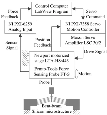
The hardware shown in Fig. 1 and 2 was used to control the interaction between a MEMS force sensor and a compliant envi-ronment. A microstructure made of 100 µm thick Silicon via mi-crofabrication was used as the spring mechanism of the environ-ment. A force sensing probe from FemtoTools AG, Switzerland, used as a manipulator, was attached to a motorized stage and the spring mechanism was attached to a stationary base. The stage was controlled through a National Instruments, Austin, Texas,
NI PXI-7358 Servo Motion Controller NI PXI-6259 Analog Input Maxon Servo Amplifier LSC 30/2 Drive Signal Position Feedback Sensor Signal Force Feedback Servo Command Probe Bent-beam Silicon microstructure Motion Newport motorized stage LTA-HS/443 Femto-Tools Force Sensing Probe FT-S Control Computer LabView Program
FIGURE 1. THE DIAGRAM OF THE EXPERIMENTAL SETUP.
Motion Sensor Probe Femto-Tools FT-S Force Sensing Probe Silicon microstructure 4mm 0.1mm
FIGURE 2. SIDE IMAGE OF THE SETUP USED.
USA servo motion controller. The force feedback was acquired through an analog input data acquisition board, and the controller was implemented in using NI LabVIEW.
The motorized stage from Newport Corporation, Santa Ana, California, USA, has a minimum incremental motion of 0.1 µm and an uni-directional repeatability of 0.5 µm. The stage also has a backlash of 12 µm.
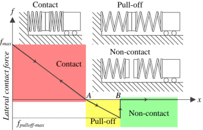
Pull-off Non-contact x Contact fpulloff-max fmax f L a te ra l co n ta ct f o rc e Contact Pull-off Non-contact A B
FIGURE 3. THE EVOLUTION OF THE LATERAL CONTACT FORCE IN THE PRESENCE OF PULL-OFF FORCE DURING LEFT SIDE AND RIGHT SIDE CONTACTS IN THE RAIL.
2.2 Scaling Issues
There are many differences between contact models at macroscale and microscale. We can mention the different pre-dominant forces, the different signal to noise ratios for sen-sors and the added nonlinearities/positioning errors for actuators. Surface force being predominant at the microscale, it is required to evaluate the influence of surface forces during the studied task. These forces appear when a contact between the environ-ment and the force sensor happens. To automatically achieve a contact/non-contact transition at the microscale, pull-off force has to be accounted for. It is the force necessary to break a con-tact due to stiction and has a predominant role when concon-tact hap-pens between microscale objects.
It was shown in [9] that the pull-off force can reach 196µN for a planar 50µm x 50µm silicon contact surface that can typ-ically happen in the present case. During the contact/non con-tact transition, the breaking of the lateral concon-tact may induce a pull-off force for each side of the contact. In this case, the evo-lution of the lateral contact force according to the position of the micropart can follow curves in Fig. 3, i.e once a contact (mi-cropart/environment) happens, the pull-off force acts as a stick-ing effect. As shown in Fig. 3, an opposite force is applied durstick-ing the withdrawal to break the contact. At point A, the lateral con-tact force is zero but the concon-tact remains due to adhesive force. The contact is broken at B when enough force is applied to bal-ance the adhesive force.
The signal to noise ratio is another difference between the microscale and macroscale. This is caused by the fact that the signals at the microscale have large bandwidths, small ampli-tudes and high noise. The noise is due to the type of components used, their sensitivity to the environmental conditions (tempera-ture, humidity, small vibrations) and the microfabrication uncer-tainties. To deal with these microscale specificities, some filters
FIGURE 4. SYSTEM MODEL BASED ON SPRING DAMPER
should be integrated taking into consideration not to change the dynamics of the signals. The bandwidth of microsystems usually contains high frequencies, so using low pass filters will affect the dynamics of the system. In addition, the controller must be able to deal with the noise and must not confuse between contact force and noise.
3 SYSTEM MODELING AND CONTROL
In this section, the model of the system used in this paper is discussed. Then, explicit force control and impedance control are studied showing the differences between these two strategies.
3.1 Model of the system
The contact interaction between a robot and the environment is typically modeled by mass-spring-damper models. In this pa-per, the proposed models are divided into two parts: an envi-ronment part modeled by a mass-spring-damper and a gripper part modeled also by mass-spring-damper. This corresponds to a flexible-gripper, flexible-part interaction scenario typically en-countered at the microscale. The proposed model is shown in Fig. 4.
In Fig. 4, m is the mass of the contact surface (gripper + environment), ms, ks and ds are respectively the mass, the
stiff-ness and the damping of the gripper, keand de are respectively
the stiffness and the damping of the environment, xsis the actual
position of the stage which moves the gripper, xdand x are
re-spectively the desired and the actual position of the environment. x, xs and xd are relative positions to the initial positions before
contact.
During contact, the dynamics equation is given by (1):
mx¨= Fgripper→m+ Fenvironment→m (1)
Where Fgripper→m and Fenvironment→mare respectively the forces
exerted form the spring and damper of the gripper to the mass and from the spring and damper of the environment to the mass. The dynamics of the system is given by (2):
FIGURE 5. EXPLICIT FORCE CONTROL SCHEME
where fmis the force exerted by the mass on the gripper and fe
is the force exerted on the environment. fmgiven by (3), is the
force measured by the force sensor.
fm= −Fgripper→m= ds( ˙x− ˙xs) + ks(x − xs) (3)
The force exerted on the environment feis given by (4).
fe= −Fenvironment→m= kex+ dex˙ (4)
Robots are usually controlled by motor efforts (force or torque). In some applications, and especially at the microscale, the robots are controlled in position or velocity instead. In this case, we change the existing control schemes where the calcu-lated command is the force to a controller in which the calcucalcu-lated command by the controller is an incremental position or velocity of a moving stage. The aim is to control the force exerted to the environment fein order to guarantee the stability of the grasp in
micromanipulation, and also to not break components.
3.2 Explicit Force Control
The explicit force control aims to control the force exerted on the environment fe in reference to a desired force fd [16].
Two types of explicit force control exist: force-based and inner position loop based. The most commonly discussed technique in the literature is the force-based explicit force control in which P, PI or PD controllers are used [17–19]. In this article, the in-ner position loop based explicit force control is used because the robotic system is controlled by position. The explicit force con-trol scheme used in this paper is given by Fig. 5. The force controller calculates the position command xs using the error ε
between the desired force and the measured force exerted on the environment feand sends it to the controlled stage. If feis not
measured, it should be estimated using the position and another measurement, if possible, fm. The form of the controller changes
in function of the application and of the requirements of the sys-tem. The most commonly used controllers are a P, PI or PD con-trollers. These controllers are used for their simplicity and their effectiveness. Other types of controllers could be used as well. An incremental controller like the one used in [14] could also be used (see Fig. 6). The idea of this controller is to compare the desired force to the output force and then the controller sends
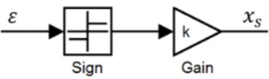
FIGURE 6. INCREMENTAL CONTROLLER
a relative position command to go forward or backward with a predefined step (gain) in function of the sign of the difference (ε = fd− fe). The advantage of this type of controller is that it
is easy to implement, robust and effective even if the system is nonlinear. The drawbacks of this controller is that the response of the system is slow or it chatters as a function of the gain of the controller (see Section 4). A PD controller could be used if the reference force is constant which is usually the case. In this case, the command could be calculated using (5).
xs= Kp( fd− fe) − Kd˙fe (5)
Where fein (5) is the measured or the estimated force exerted on
the environment.
3.3 Impedance Control
The aim of the impedance control is to control the dynamics of contact. The dynamics of contact are set to follow a desired impedance. It has been demonstrated in [20] that an impedance controller with force feedback contains an explicit force con-troller. In the case of impedance control with force feedback, the force is also controlled in reference to a desired force. Using the Laplace transform of (2) and (3), (6) could be derived. The position x is replaced by X (s) = fm(s) dss+ks+ Xs(s) using (3): ms2Xs(s) + ms2+ dss+ ks dss+ ks Fm(s) + Fe(s) = 0 (6)
where s is the complex argument, Xs, Fmand Feare the Laplace
transforms of xs, fmand ferespectively.
The desired impedance proposed by Hogan in [11], using the Laplace transform, is given by (7).
Xd(s) − X (s) =
1 Mds2+ Dds+ Kd
Fe(s) (7)
where Xd is the desired position, Md, Ddand Kd define the
de-sired impedance parameters of the system. Using (6) and (7), the command sent to the stage xsis given by (8):
Xs(s) = Mds 2+D ds+Kd (Md−m)s2+Dds+KdXd(s)− (Md−m)s2+(Dd−ds)p+(Kd−ks) (dss+ks)((Md−m)s2+Dds+Kd)Fm(s) (8)
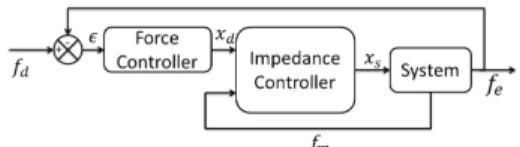
FIGURE 7. IMPEDANCE CONTROL SCHEME
An external force control loop could be added to the internal impedance controller. The goal of this controller is not only to control the impedance of the contact but also to control the ex-erted force in reference to a desired force. The final impedance control scheme used in this paper is given by Fig. 7 using the controller equation defined in (8) where the controller has two inputs, the desired position xd, calculated by the force controller,
and the force measured by the force sensor fm. The output of
the controller xsis the position command sent to the system. The
force controller in Fig. 7 could be a P, PD, or PI controller. The proportional force controller is chosen in this case because of its simplicity and to guarantee the stability of the controller which is not the case with the integral controller.
4 EXPERIMENTAL RESULTS
In this section, the different types of force control discussed in Section 3 are tested, the dynamical behaviors will be shown and the performances will be compared. These experiments were carried out on the experimental system depicted in Fig. 1 and 2 at the University of Texas at Arlington. The control schemes shown in Fig. 5 and 7 consist of motion control, force sensing hardware and a control program developed in LabView as in Fig. 1.
4.1 Estimation of the force exerted on the environ-ment
Before detailing the experimental results, the force feedback is the force measured by the force sensor fm which is not the
same as the force exerted on the environment feas shown in (2).
Thus, fe should be estimated. Using (2), (3) and (4) fe could
be estimated using two possible equations (9) or (10). In the following two equations, the position x is replaced by X (s) =
Fe(s) des+ke using (4): Fe(s) = dsdes2+ (dske+ deks)s + kske ms2+ (d s+ de)s + (ks+ ke) Xs(s) (9) Fe(s) = des+ ke ms2+ d es+ ke Fm(s) (10)
In (9), feis estimated using the measurement of the position, xs,
the measurement of the stage position given by the encoder, and
FIGURE 8. SYSTEM RESPONSE FOR AN INCREMENTAL FORCE CONTROLLER (a) WITH A BIG STEP OF THE CON-TROLLER, (b) WITH A SMALL STEP OF THE CONTROLLER
assumed noiseless. Thus, (9) estimates fewithout noise.
How-ever, (10) estimates feusing fmand ˙fm. Where fm is the force
measured by the force sensor which is noisy (for the force sensor used the noise has amplitude of 100 µN). Since ˙fmis very noisy,
fe will also be very noisy. The amplitude of noise could be
re-duced, in our case, using a low pass filter to filter the measured force fm. Using the estimation of fegiven by (9) appears to be
a good idea. However, a backlash problem of the stage causes a big problem for estimating febecause the measurement of the
stage will not be reliable if many reference signals are applied. Thus, (10) is used to estimate fe.
Before starting the experiments, the parameters used for control m, ds and de are calculated theoretically and ke and ks
are estimated experimentally. The calculation of the mass was done using the volume of the system. The damping coefficients were calculated using the values of the damping of the Silicon and the sections of the system. ks was estimated by applying a
force by the force sensor to a stiff environment and measuring the displacement of the stage. kewas estimated by applying a force
by the force sensor to the flexible environment used and mea-suring the displacement of the environment. The values used for calculating the control laws are m ≈ 70 mg, ds≈ de≈ 0.3 Ns/m,
ke≈ 20 N/m and ks≈ 5000 N/m.
4.2 Experimental results for the explicit force control
As discussed in Section 3, two types of explicit force control are tested and compared: a PD controller and an incremental con-troller. The response of the system in presence of an incremental control and using the estimation of fe given in (9) is shown in
Fig. 8.
First, the effect of the step (gain in Fig. 6) of the incremental controller influences the behavior of the system. Big step incre-ments imply a low response time but the amplitude of chattering in the static part is also big. However, small step increments im-plies a big response time and a smaller amplitude of chattering
FIGURE 9. SYSTEM RESPONSE FOR A PD FORCE CON-TROLLER
FIGURE 10. SYSTEM RESPONSE FOR AN IMPEDANCE CON-TROLLER
in the static part. Secondly, in these figures, the effect of back-lash appears. The estimated force fe returns to zero while the
measured force fmdoes not. The force feedback being the
esti-mated value of feusing (9), the controller controls the estimated
force fecorrectly but the estimation of feis wrong because of the
backlash problem.
Using a PD controller could be a solution to have a good re-sponse time without chattering in the static part. This type of controller is used because it is simple and gives good perfor-mance. The controller used is given by (5). The performance is given in Fig. 9. In this case, the estimation of fegiven by (10)
with a low pass filter is used. Fig. 9 shows that feand fmfollow
the same shape and they are almost the same in the static part. However, feand fmare noisy. The response time of the system
is good (≈ 1s). It could be improved by modifying the gains of the PD controller but there is a risk that the system will become unstable in this case.
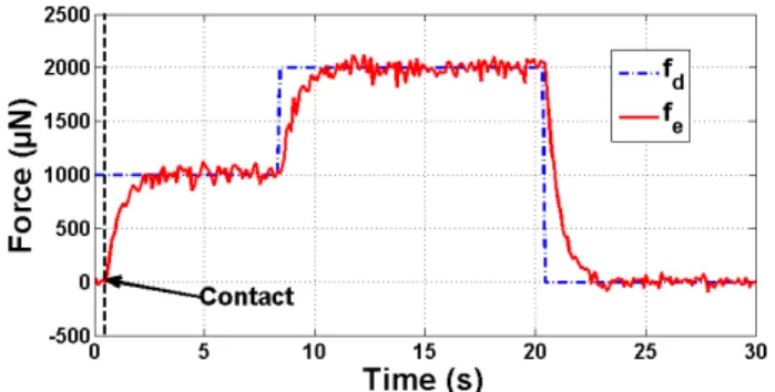
4.3 Experimental results for the impedance control
The impedance control block shown in Fig. 7 and the con-troller given in (8) are used to control the system. Fig. 10 shows
FIGURE 11. SYSTEM RESPONSE TO IMPEDANCE CONTROL IN PRESENCE OF A STIFF ENVIRONMENT
the response of the system using the impedance control scheme defined. The system response is a first order with a response time of ≈ 1s. The behavior is close to the explicit force control. This fact is because the impedance control is used with an external force control feedback. The main difference is in terms of the impedance of the system during contact. The impedance control aims to set the dynamics of the system to a desired impedance defined by the user. Comparing fe in Fig. 9 and Fig. 10, the
response of the controlled system is first order in Fig. 10 while in Fig. 9 it exhibits a transient behavior before setting feto fd.
In impedance control, the desired dynamics of the response of the system is set using three parameters Md, Ddand Kd. Thus, the controller controls at the same time the impedance of the con-trol and the fein reference to fd. Some experiments have shown
that the use of the proposed impedance control scheme is limited to a flexible environment. However, the stability of the proposed controller is not guaranteed for a very stiff environment as shown in Fig. 11.
A simple comparison between the explicit force control and impedance control results shown in Fig. 9 and Fig. 10 shows that the explicit force controller is simpler than the impedance controller in terms of controller complexity. Both of them are robust. The contact transition for the impedance control is better than the explicit force control. The impedance control is more flexible in design (3 parameters to control) and shows good dis-turbance rejection.
For instance, the controller is able to set fe to zero when
a zero force reference is applied but it is not able to break the contact due to pull-off force. The specific effect due to the mi-croscale is discussed in the following section.
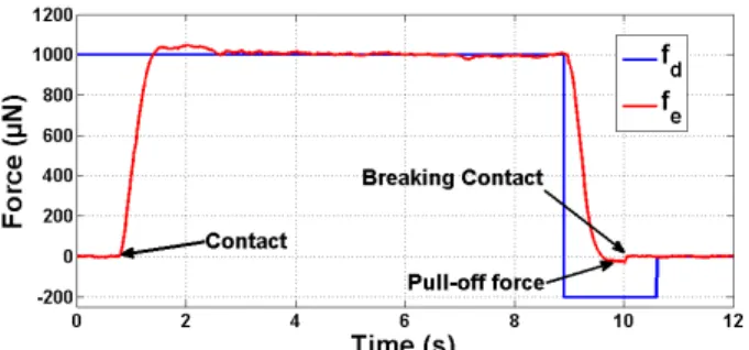
4.4 Experimental results showing the pull-off force effect
As shown in Section 2, the pull-off force could appear when a contact happens. The pull-off force acts as a sticking effect. During the experiment, once the contact happens and we aim to
FIGURE 12. THE PULL-OFF FORCE APPEARS WHILE BREAK-ING THE CONTACT. EXPERIMENT DONE FOR IMPEDANCE CONTROL SCHEME
separate the contact, setting the desired force to zero will not sep-arate the contact, the contact will persist although the measured force is zero. An easy way to separate the contact is to apply a negative force reference for a short time and then return the de-sired force to zero. When a negative force reference is applied, the controller aims to set the desired force to the reference and then a command is sent to the stage to come back and then the contact is broken. During this phase, a negative measured force appears due to the pull-off force. This force is not constant dur-ing the experiments. It varies as a function of many variables (angle, surface, etc...) [9]. Fig. 12, shows the effect of pull-off force on the system. The pull-off force is the negative part of the force fe. It appears while breaking the contact. The contact is
not broken directly when the force returns to zero.
Fig. 12 shows also the effect of modifying the estimated val-ues of the parameters. This modification changes the response of the system to a second order with an overshoot in place of a first order response. Other experiments have shown that the impedance controller behavior is acceptable until a parameter change of 40 %. More than 40 %, the reponse of the system will not be acceptable and the system could become unstable.
The problem of signal to noise ratio is avoided, in our case, by adding a low pass filter to the signal because the bandwidth of the system does not contain high frequencies. The results show that the noise level of the output signal feis small due to filtering.
5 CONCLUSION
In this paper, a comparison between explicit force control and impedance control for microscale manipulation applications was carried out using experimental results. It was shown that unique effects specific to the microscale affect the effectiveness of these force controllers. Not surprisingly, impedance control showed better performance than explicit force control. Similar to the macroscale, impedance control is better at controlling the
dynamics of contact between the manipulator and object. But unlike the macroscale, impedance control is also better at ex-erting forces on the environment, and more robust at handling flexible components with unknown stiffness. The impedance control scheme used is robust for flexible components and for a small variation of elements. The use of impedance control is limited in presence of a stiff environment. Another limitation would be the parameter uncertainties. Results have shown that the impedance control scheme used in this paper was able to deal with up to 40 % change in the parameters. It was shown that most of the challenges in force control are common for microscale and macroscale but the main differences are the presence of pull-off force at microscale and the signal to noise ratio. A simple method to deal with the pull-off force was proposed. Filtering solves the main problems of the signal to noise ratio, at the expense of bandwidth. To use the impedance control, the parameters of the system should be known m, ke, ks, ... which was the case in this
paper. If some parameters are unknown, an adaptive impedance controller could be used to estimate the unknown parameters dur-ing the experiments. This will be the focus of future work.
This paper shows that the use of impedance control for mi-croscale is a promising topic in coming years specially with the progress of force control for some microassembly and microma-nipulation applications. The impedance control could be used for many microassembly tasks (for picking and releasing a cropart, for guiding a micropart in a rail or for inserting a mi-cropart in a hole). This work was done for a 1 DOF moving stage and it will be extended to more complex systems.
ACKNOWLEDGMENT
The authors would like to thank the Net4m project for fund-ing the travel of Bilal Komati from the University of Franche-Comt´e to the University of Texas at Arlington, the region Franche-Comt´e in France and the University of Texas at Arling-ton Research Institute for funding the equipment and hosting the experiments presented in this paper.
REFERENCES
[1] Savia, M., and Koivo, H. N., Aug. 2009. “Contact micromanipulation-survey of strategies”. IEEE/ASME Transactions on Mechatronics, vol. 14, no. 4, pp. pp. 504– 514.
[2] Dechev, N., Ren, L., Liu, W., Cleghorn, W., and Mills, J., May 2006. “Development of a 6 degree of freedom robotic micromanipulation for use in 3d mems microassembly”. IEEE International Conference on Robotics and Automa-tion, Orlando, FL, p. 281288.
[3] Das, A. N., Zhang, P., Lee, W. H., Stephanou, H., and Popa, D., 2007. “µ3: Multiscale, deterministic micro-nano as-sembly system for construction of on-wafer microrobots”.
IEEE International Conference on Robotics and Automa-tion, Roma, Italia, pp. 461 – 466.
[4] Wang, L., Ren, L., Mills, J., and Cleghorn, W., 2010. “Automated 3-d micrograsping tasks performed by vision-based control”. IEEE Transactions on Automation Science and Engineering, 7, pp. 417 – 426.
[5] Anis, Y., Holl, M., and Meldrum, D., 2010. “Automated selection and placement of single cells using vision-based feedback control”. IEEE Transactions on Automation Sci-ence and Engineering, 7, July, pp. 598 – 606.
[6] Greminger, M., and Nelson, B., March 2004. “Vision-based force measurement”. IEEE Transactions on Pattern Analy-sis and Machine Intelligence, pp. 290 – 298.
[7] Liu, X., Sun, Y., Wang, W., and Lansdorp, B. M., July 2007. “Vision-based cellular force measurement using an elastic microfabricated device”. Journal of Micromechanics and Microengineering, 17.
[8] http://www.femtotools.com/index.php?id=products-g. [9] Rabenorosoa, K., Clevy, C., Lutz, P., Gauthier, M., and
Rougeot, P., 2009. “Measurement of pull-off force for pla-nar contact at the microscale”. Micro Nano Letters, 4, pp. 148 –154.
[10] Seraji, H., 1994. “Adaptive admittance control: An ap-proach to explicit force control in compliant motion”. In Jet Propulsion Laboratory California Institute of Technol-ogy Pasadena, CA 91109.
[11] Hogan, N., 1985. “Impedance control - an approach to ma-nipulation. i - theory. ii - implementation. iii - applications”. ASME Transactions Journal of Dynamic Systems and Mea-surement Control B, 107, p. 1 24.
[12] Singh, S., and Popa, D., Dec 1995. “An analysis of some fundamental problems in adaptive control of force and impedance behavior: theory and experiments”. IEEE Transactions on Robotics and Automation, 11, pp. 912 – 921.
[13] Raibert, M., and Craig, J. J., 1981. “Hybrid position/force control of manipulators”. Transactions of ASME, Jour-nal of Dynamic Systems, Measurement, and Control, 102, pp. 126–133.
[14] Komati, B., Rabenorosoa, K., Cl´evy, C., and Lutz, P., 2013. “Automated guiding task of a flexible micropart us-ing a two-sensus-ing-fus-inger microgripper”. IEEE Transactions on Automation, Science and Engineering, PP, Isue: 99, pp. 1 – 10, paper online at http://ieeexplore.ieee.org/, DOI 10.1109/TASE.2013.2241761.
[15] Lu, Z., Chen, P. C. Y., Ganapathy, A., Zhao, G., Nam, J., Yang, G., Burdet, E., Teo, C., Meng, Q., and Lin, W., 2006. “A force-feedback control system for micro-assembly”. Journal of Micromechecanics Microengineer-ing, 16, pp. 1861–1868.
[16] Volpe, R., and Khosla, P., Nov 1993. “A theoretical and experimental investigation of explicit force control
strate-gies for manipulators”. IEEE Transactions on Automatic Control, 38 , Issue: 11, pp. 1634 – 1650.
[17] An, C., and Hollerbach, J., Mar 1987. “Dynamic stabil-ity issues in force control of manipulators”. IEEE Interna-tional Conference on Robotics and Automation, pp. 890 – 896.
[18] Colgate, E., and Hogan, N., May 1989. “An analysis of contact instability in terms of passive physical equivalents”. IEEE International Conference on Robotics and Automa-tion, pp. 404 – 409.
[19] Eppinger, S., and Seering, W., Mar 1987. “Understand-ing bandwidth limitations in robot force control”. IEEE International Conference on Robotics and Automation, 4, pp. 904 – 909.
[20] Volpe, R., Sept. 1990. “Real and artificial forces in the con-trol of manipulators: Theory and experiments”. PhD thesis, Carnegie Mellon Univ., Dep. of Physics, The Robotics In-stitute.