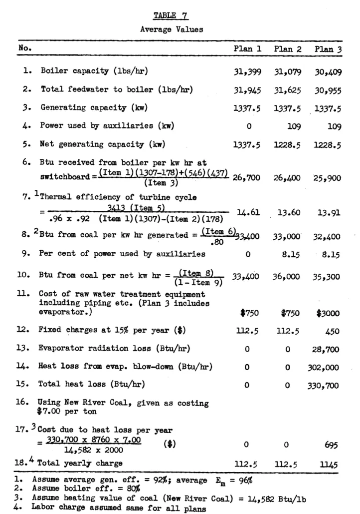
by
Aboudi Robin Mowlem B.A. Columbia College B.S. Columbia University
Submitted in Partial Fulfillment of the Requirements for the Degree of
Master of Science
from the
MASSACHUSETTS INSTITUTE OF TECHNOLOGY
1946
Signature of Author Signature of Professor in Charge of Thesis(-N
Signature of Chairman of Department Co 'ittee on Graduate StudkntsDepartment of Mechanical Engineering February 11, 1946
M.I.T. Dormitories
Cambridge 39, Mass. February 11, 1946Professor George W. Swett Secretary of the Faculty
Massachusetts Institute of Technology Cambridge, Massachusetts
Dear Sir:
In partial fulfillment of the requirements for the degree of Master of Science in Mechanical Engineering, I re-spectfully submit my thesis entitled, "Design of Factory Power Plant".
Respectfully submitted,
Aboudi Mowlem
The author wishes to express his appreciation to Professor James Holt, under whom this work cas carried out, for his help and useful suggestions.
I.
II.
III.
V.VI.
VII.
VIII.
CONTENTS Introduction .... Statement of Problem ...Buy or Make Power? ...
Economics of Design ... ...
Conditions to Meet Prior to Design Design of the Steam Plant ... Description of the New Plant
Conclusion ... .. Appendix
1. Turbine Calculations ... ... .. 2. Condenser Calculations
3. Heat Balance Calculations
4. Boilers ... ...
5. Combustion Calculations
6. Stokers ... ..
7. Furnace Calculations ...
8. Coal and Ash Handling... 9. Coal Bunker ... ...
10. Coal Conveyor
11. Economizers ...
12. The Draft System ...
13. Chimney and Breeching ...
14. Piping ...
15. Pumps ...
16. Power Required by Auxiliaires
Page
13
4
9
12
16
22
26
28
36
41
5055
61
63
64
65
66
68
72
79
83
87
90
18. Investigation for Purchasing Power and Producing Manufacturing Steam by
the Installation of a Low Pressure Boiler .... 94 19. Cost of Purchasing Power ...
98
Bibliography ... 101I.
INTRODUCTION
An industrial factory requires power and heating and manufactur-ing steam. The question arises before the designer of the choice be.-tween several plans of supplying the load. Should he install a plant to supply both the power and process steam, or should he purchase the power and install a low pressure boiler plant? Should he purchase both power and process steam, interchange with a utility company or purchase part of the power and generate the remainder and the process steam? His choice must be based on the most economical scheme, which must also be flexible and reliable as well as adaptable to the partic-ular case under consideration, for no one scheme has all the advantages and no disadvantages.
Two methods of supplying the load are selected in this work for detailed investigation. One is the design of a steam power plant supplying both the power and the process steam. High plant thermal efficiency is sought but not to such an extent as to make an investment larger than for a plant with lower efficiency. The design is discussed in detail in section VI, while the calculations are found in the appen-dix. The equipment, in many cases, is selected from a number of designs according to economical performance and suitability. The other method is to purchase power and install a low pressure boiler plant. The rate used is the Block Hopkinson demand rate.
A cost comparison of the two methods is made and the annual saving realizable by the building of a steam power plant over the other method is found to be $33,310. which can pay for a new and complete
new power plant be installed to handle the power and steam loads.
The
cost of the power is
1.935 cents per kw br,
a reasonable value for the
size of the plant in question.
Drawings of overall plant layout have been made and can be
found in section VIII.
II.
STATEMENT OF PROBLEM
A certain factory is to build a new plant and must decide
whether or not they should generate their own power or purchase power
from a neighboring central station and install low pressure boilers
to supply steam for heating and manufacturing.
The plant engineer is requested to go over the plans and
made a survey, design a power plant and decide whether or not to
pur-case power.
The plant survey was as follows:
1.
The average daily load during the year would be as
shown below.
No load Sunday except steam for heating.
Maximum estimated power load
=
2250 kw.
2.
Average yearly steam load curve for heating and
manu-facturing steam at 25 psi gage is also shown below.
Condensate can be returned at a probable temperature
of
140* F.
3.
The plant is located on a river of fresh water which
can be used for condensing purposes but must be
filtered before used in boilers.
Summer water
temper-ature is 70* F.
4.
There is plenty of space available near river and
plant. Ground level about 6 feet above river. Tests
show good gravel bottom.
5. Coal can be
obtained at
$7.00 per ton over crusher
delivered by rail. Use New River coal.
6. Determine initial steam temperature to produce dry
saturated steam at the bleeder point. Use
450 psia
LL r T --. Ti-i~ ~ 4.-I.-.. -T 4 -4 If.. I-t-. -. 1~~ 4 .-I ---+ --L -I -> --4 It I 4 4--,.--- 4 -t L24 ~T t~ k-,. -t
-- I
K
K-
4-i~I~-~
-I -~~
t--4 V --t -r -I --, - 4-44t
ii>-tT~4 -44 -4 -r~t - 4 --~7 t -I ~-i 4-4-ii
-4-.-* 4 1 TA -4 -- -4--4I
-i K *1 -1 --'--I IIK
T- I 4 -- 4 } -] T- -~~1 ~I-'~-IK-Vh 1
K
~- V-t -~ --- 7-I, -I .4 44 4~4-4--! f- 7-* Vj --4 '-t--4--~ Vt' TAF-
---1
4--- -t --- 4-+4 + --4 t - --T --4-- - -4-- Ii--rt~ ~'-1 ---H -4-4K:
4
4 .4 -. --~1~L
1L.__ ____ - __ ----4- + . I.-4 *1~ -~t-~ i-I-' .--Ii
>1>
-t-j 1-OD~7~.9-
--4 1* -~ ~j4 4 -4-, --- 4 -14-1-
-II--
F-I- -. 1 4 L2., 14 --T --_-_-_-_4_- ---4 -t -- J L-I-Ft
i- 4 1..~
.4- 4 T~] iT- 4-K' 1 K-i 4-~ - ~ t -ii.i1~'
~
4 44L -- 4 -4-t -T-I A V-~4-I ~ * -.1..
~
~{-
Ii~I
:
1
t4
Art 4---1 4.I7~
QL~
.14 4 + ~-~ 1~ t 2 T7V4
-J'' T 4~ V. -4 4 1-4- -* 1.~. * A. 4- -L ~- I '~t ~..1
~.4J t + ~ ~ r4jtj
4 4 . LL T -"-- t -A4 -1L- --~ 4 44 44 --444 1~
42J~
~
~
4{-4---- -4 t4 1 * -* --- ---- -+ t -S4 --4 -4 -i - ---L --- 4'--. -4 i .. l~
r1~~
't-+~---*
4~~t
-4 --.--; -4 L -- 4T H+ --4 --- --F- .. ,4 t 4-4 -'.. 4- 4 -t 'A-*'~1 -- 4- 1* 1~ '~1 4.~rP
4$d~ . .9 4-F ,. 1 4--..i7~.
-t -14i--ri--r --: r--4 ~
*
-~
i-I--i--i-, -F4
-t
-4 T1-44 -*
-1
r
-2
4 tI
r1
-The entire problem at hand is to decide whether to purchase
power and install a process steam plant or to generate our own power
to handle the load and the process steam required.
Naturally, the
ultimate basis of selection is the cheapest or the most economical
plan possible. No definite policy
or set of rates can be set down
upon which plant owners
can decide the
question
of making versus
buy-ing power.
But engineering knowledge backed by experience make
cer-tain classifications possible.
It pays to purchase power
1. If power rates are right, together with cost of
trans-mission and transformer loss-in plants of small size
and moderate power demand with little or no need for
process steam.
2. If business is growing so very rapidly that the risk
of building own plant is unwarranted because of the
changing size of generating units and type of
equip-ment.
3.
If by-product power is insufficient to meet
require-ments. The best economy may be served here by
pur-chasing the balance of energy needed.
4.
If exhaust steam can be used for heating during cold
months only. Purchase
of power at suitable rates in
the warm months may result in better economy than
operating non-condensing engines or turbines, or
Diesel units.
1. In large or small establishments, if all of the exhaust steam from the power units can be utilized for heating or for process work. This may also be true (as in the plant under consideration) when part
of the exhaust is so utilized by bleeding from the turbine. The number of manufacturing plants which can profit by this method has largely increased--even those of very small capacity such as 100 kw plants. Where the process steam is one half of the power load, this method may cut down the fuel con-sumption by half.
2. Where there is a continuous moderate or large power demand throughout, even if there is no process steam load. Under these conditions the overhead cost per kw hr is small, so that with efficient design a
sav-ing can be made.
3.
When a considerable boiler plant must in any case be installed for heating or process work. It may be possible here to install a power unit without adding boiler capacity so that the increase in overhead charge is only for the power unit.Fuel is the greatest single item entering into the cost of power. It makes for the many possibilities for economy in the by-product power plant which are independent of the steam pressure re-quired for the process. "An ordinary simple steam-engine unit whose exhaust is absorbed in building warming or heating liquids or drying processes is delivering by-product electrical energy for a small
6
fraction of the fuel required per kilowatt-hour by the most 'supert of super power plants."*
Of course, fuel is not the only means with which to compare power costs. The following table illustrates the influence of the
other factors.
Power Cost Items**
Item Generated Power Purchased Power
Fuel May use more fuel. May use less fuel, but Modernizing old plant fuel for heating and will reduce this quan- process must be continued.
tity and cost.
Supplies More supplies. Less supplies, but sup-plies for boiler house
still needed.
Labor More labor, but modern- Less labor, but steam izing may reduce amount. still requires some.-Maintenance and More of these items Less of these items. For
repairs which, however, modern- boiler plant may be the izing may reduce. same.
Fixed charges New fixed charges if New fixed charges caused plant is to be improved, by installation of pur-otherwise none. chased power.
Purchased power None if all the power Cost of purchased power is generated. including transformer
losses.
Total Sum Sum
Improvements in either scheme may often throw the decision in its favor. There are many situations even with plants operating continually for twenty-four hours a day with high power factors where
* D. Myers, Reducing Indurial Power Costs, p. 66, New York, 1935. **D. Myers, op~cit., p. 66.
F
7
power can be generated more cheaply than by purchasing it, where it pays, nevertheless, to purchase power if the difference is not too great. This fact is illustrated in the case where the limited avail-able capital can be turned over more rapidly by improvements in the methods of production than by investment in a private power plant.
There are compromise cases where power is purchased as well as made in an economical balance between the utility company and the
industrial plant. Also when the load increases and power expansion is necessary, this expansion is often more easily covered by the purchase of power. The necessity for reserve capacity is sometimes relieved by cooperation with the utility company through the supply to the util-ity company of surplus power by the industrial plant or the latter be-ing supplied with utility power in cases of peak and emergency loads.
For the plant under consideration we may choose one of several alternatives (as indicated above) on the most economical basis. The alternatives are:
1. Make own power and heating and process steam.
2. Purchase power and produce heating and process steam in a low pressure boiler plant.
3. Purchase power and process steam.
4.
Interchange of power with a utility company.5.
Part purchase of power and generate remainder and the process steam.From the above discussion, we note that only the first two alternatives can be suitable for the plant under consideration on a competitive basis since the fourth finds sway in large scale power generation, while the fifth is adaptable only to an old or existing
plant whose load has slightly increased or in cases of emergency. The third method is of value when the demands of power and process steam are both small.
-An investigation of the first two methods has been made and it is recommended to generate our own power and process steam. This method has the added advantage that the power plant can be located near the factory so that the voltage regulation is closer and the power transmission losses smaller. Often, steam cannot be purchased from a utility company, so that a boiler plant must be installed in any case and consequently it is more economical to generate the power as well as the steam.
Since process steam is required in the scheme adopted (gen-. erating own power), steam must be the working medium in the power plant, otherwise Diesel power could be efficiently and reliably used.
IV. ECONOMICS OF DESIGN
The examination of an industrial power plant should be based on suitability, the possibility of future enlargement, its proper and economical operation, availability of correct and continuous operat-ing data and cost figures. An industrial plant differs from the cen-tral station in the fixity of load curve which is the main requirement the latter must meet. Changes in product, process or demand neces-sarily impose varying load conditions on the whole plant or its sub-divisions not found in the central station. This difference is well illustrated in the matter of providing reserve capacity. "Some pro-cesses are continuous and any interruption in the flow of power or steam may cause a great loss in the semi-finished product. In some textile processes, for instance, a slight change in electrical fre-quency causes considerable loss"* In other cases, such as power supply to a mine, production can be stopped without much loss until service is resumed. In general, however, to be perfectly reliable, an industrial plant must have enough reserve capacity (usually equal to the largest unit) to meet any demand of power and process steam at any time. Reserve capacity must also have an eye for the future en-largement of the plant. This reserve must not be too large, but its amount must be based on an economical compromise between the increased investment, estimate of load growth and the worth of great reliability.
The cost of producing power is made up of two classes of costs-fixed and operating charges. The former deals with the plant itself, practically regardless of its use, and consists of interest on the investment, depreciation, taxes and insurance. The latter
includes the cost of fuel, labor, oil, waste, supplies, and maintenance. The most desirable plant is that one with least total cost (sum of the two charges).
The conditions affecting investment are as follows:*
1. Location. The cost of power transmission is appre-ciably reduced if the power plant is located close to the manufacturing plant. It should also be located near an adequate supply of water for condensing pur-poses (a river in the plant under consideration); as much as possible on flat ground free from swamps, rock and gravel so that the foundation cost can be kept at a minimum level.
2. Manner in which fuel is received. If the coal is water borne, considerable investment must be made in docking and unloading facilities. Similar costs are not required where the coal is received by rail. If
gas or oil is used, their handling is relatively unimportant because it is usually very cheap and
simple.
3. Values of plant size. If the land is very expensive,
as in metropolitan areas, it is necessary that the plant be built on the basis of maximum capacity per square foot of area, even at the expense of good design. This condition dictates the design of tall and often cumbersome buildings greatly crowded with equipment.
4.
Size of load. Low unit cost results if as large units as can be fitted to the load curve are installed.5. Architectural treatment. This depends upon the pre-ference of the management. Cost comparison would be superfluous in this case.
6. Fuel cost. Since this is the largest single item in the production cost of power, it is the controlling factor in plant investment. Where the fuel cost is high, equipment for improving plant efficiency is necessary. On the other hand, if the fuel cost is low, investment for efficiency improvement is un-justified.
7. Safety of operation. Investment required for this item is not based on an economical viewpoint, but must be made in any case, if the plant is to be safe and prosperous. It is an important item which the designer cannot afford to overlook.
V. CONDITIONS TO MEET PRIOR TO DESIGN
A load curve is useful and necessary for plant analysis,
proper operation, prediction of magnitude and character of load on
the power plant. No two load curves are ever identical, but they
are similar in that they all have peaks and valleys. The ideal load
curve is a flat rectangle, but this is never realized in practice. A
lighting load is usually characterized by sharp peaks during the
even-ing hours, thunderstorms or special events such as New Year's Eve at
midnight, and long low valleys for the remainder of the time.
On the
other hand, the industrial power load has long, relatively flat, peaks
during working hours, but almost disappears later.
By flattening out
the load curve, the load factor is increased resulting in the operation
of boilers at a more uniform load, which is reflected in higher boiler
and furnace efficiency.
It is evident
that the higher the load factor,
the cheaper is the cost per kw hr, the fixed charges remaining the
same regardless whether the plant is running at half load, full load,
full time, half time or idle.
For the plant under consideration, the load curve is given
and nothing can be done to improve or change it.
In other words, the
plant must be designed to meet this curve as economically as possible.
The load is relatively steady and high as compared with the maximum
during mcs t of the day and then falls off to another steady demand.
The morning is well started with 78% (at 8:00 a.m.) of maximum demand
and continues for the remainder of the day with a steady average of
about
83% (1875 kw) of maximum demand (2250 kw).
From about 12 midnight
until early morning a steady demand of about 28% (625 kw) of maximum
is required. The load curve is therefore seen to be relatively favor-. able. The average load gives a dilay load factor of 59.5%, an un-usually high value. This desirable condition is grestly impaired by the stoppage of power demand during Sundays. The boilers are kept warm during winter, however, because steam must be supplied for heat-. ing. During the summer months added cost is incurred in the necessity of purchasing extra coal for banking the boilers.
The process load is steady during the day and relatively so during the month, but the fluctuation per year is quite high (50% of maximum bleed). The average yearly bleed is nevertheless 73% of the maximum, which is about 50% of the total maximum turbine throttle. As was stated in a previous section, this ratio of bleed to throttle flow makes for greater economical coal consumption. The lowest bleed load continues for 33% of the year.
The power and bleed loads given must be fitted with the most suitable and economical power units. In general, the turbine has many advantages over the reciprocating steam engine. It requires only a fraction of the floor space. Its foundation bulk and cost are
greatly reduced, not only because of the small weight and floor space of the turbine and generator, but because of the lack of vibration introduced by reciprocating parts. Besides, turbine speeds are more adaptable to generator drives, decreasing investment costs still fur-ther. Steam and exhaust piping are of smaller size owing to the con-tinuous flow of steam to the turbine, which has no piston and cylinder to be lubricated thus saving the expense of cylinder oil and maintaining the exhaust steam and condensate oil-free. Non-condensing steam
steam per kw hr than a non-condensing turbine, but for larger capaci-ties the opposite is true. Since the process steam demand does not coincide with that required for power, a non-condensing turbine can-not be used as the main unit and a bleeder turbine is necessarily imposed upon the designer for selection. There are many alternatives possible for choosing the number and sizes of the power units. These alternatives are listed below in accordance with standard sizes.
Item Plan 1 Plan 2 Plan 3 Plan 4
Units Used:
1. Bleeding turbine (kw) 2-1500 2-2500 3-1000 2-1250 2. Non-bleeding turbine (kw) 1-1000 0 1-1000 1-1000 Spare Unit (kw) 1-1500 1-2500 1-1000 1-1000
Total Number of Units 3 2 4 3
Installed Capacity (kw) 4000 5000 4000 3500 Maximum Load (kw) 2250 2250 2250 2250 Reserve Capacity (kw) 1750 2750 1750 1250 Average Load (kw) 1337.5 1337.5 1337.5 1337.5
Load Factor
(%)
59.5
59.5
59.5
59.5
Capacity Factor(%)
33.4 26.7 33.4 38.2The necessity for spare capacity, usually equal to the size of the largest unit, has already been pointed out and is seen to be common to all plans. The capacity factor varies little for all plans so that a reasonably equal use is made of the installed capacity.
The most economical selection is the largest unit that can be installed, for as turbine size increases, weight, floor area and
consequently cost per unit of capacity dect'ease. By increasing steam pressures and temperatures, the station heat consumption can be de-creased. Therefore, as units increase in size, steam pressures and temperatures also increase with a resultant lowering of steam con-sumption and increase in station efficiency. This consideration urges the rejection of plans 3 and
4.
In plan 2, the capacity is very large and the unit the most efficient of all four plans, but for most of the time by far it would have to run much below rating, never developing its maximum power. This poor load factor on the turbine makes it run inefficiently. Besides, the installed capacity is highest and theinvestment cost likewise greatest. Plan 3 has the advantages of greater reliability and flexibility but these do not outweigh the disadvantages of poor efficiency and higher cost per unit of capacity. Plan 1 is more flexible than plan 2, as well as more economical. This is the plan to adopt, although it must be recognized that each plan has its advantages, and the selection of plan 1 is arrived at through the most economical compromise. Both the bleeding and straight condensing tur-bines in plan 1 operate at approximately three-quarter rating most of the time. The latter has a better engine efficiency than the non-con-densing type.
The boiler, as well as other items of design, are considered in a later section.
VI. DESIGN OF THE STEAM PLANT
Having decided upon the means with which to supply the manu-facturing plant with power and process steam and upon the plant loca-tion and site, the designer must next select the equipment which will produce the required amount of power with the greatest reliability at the lowest total cost. Where the load is variable, as in the proposed plant, equipment with a flat-topped efficiency curve is more desirable than with a peaked one.
For each combination of fuel cost, load factor and capacity factor, there is an optimum steam pressure and temperature which gives the lowest cost of power. With higher pressures and temperatures the thermal efficiency of a steam prime mover is increased thereby saving fuel cost. However, as pressures go up the investment cost per unit of capacity increases, so that an economical balance must be maintained between efficiency and investment. On this basis the steam pressure is selected. For the proposed plant a steam pressure of 450 psia is
designated in the problem. This figure is in accordance with optimum conditions. The steam temperature is determined from the condition that the process steam is bled dry saturated at 25 psi gage. (See Appendix)
The vacuum which it is possible to attain depends upon the inlet temperature of the cooling water and the quantity of cooling water passing through the condenser. Summer water temperature is given as 70* F. This temperature does not vary greatly throughout the year. If it is lower than this value (as in winter) a better vacuum results in any case. Therefore, this temperature is assumed as the design
condition. The selection of the optimum vacuum is one of balancing the saving due to decreased steam consumption by the turbine against the increased pumping costs and the increased investment cost to attain the high vacuum. Also as the vacuum increases, the volume of the air in the water to be handled by the air pump increases very rapidly. Taking all factors into account a 28" Hg vacuum is selected. The statement of the problem with regard to ground level and condens-ing water implies the adoption of a low level jet condenser. The
feature of this condenser is that it can be operated with a 5* terminal difference between injection water temperature and steam temperature corresponding to the pressure in the condenser. A minimum quantity of injection water is handled. A multi-jet condenser has a more efficient removal pump but uses more injection water.
A low level jet condenser is finally designed under each turbine, together with all auxiliaries such as removal and injection pumps as well as the steam jet air pumps. The design also uses expan-sion joints to protect the turbine against upward thrust. The removal pumps discharge the mixture of water and steam back to the river
down-stream.
It was decided in an earlier section that two 1500 kw bleed-ing turbines (one spare) and one straight condensing 1000 kw turbine will be used as the power generating units in the plant. The most economical selection of boilers is subject to principles similar to the economical selection of turbi'nes. The water tube boiler is the most suitable far large power plants because large powers can be
ob-tained from single units due to the saving in floor space and because "high steam pressures in large units can be carried without any
appre-ciable thickening of metal through which the heat of fire is
trans-mitted."* Almost any type of water-tube boiler could fit a new installa-tion equally well. The selection is one of floor space, investment and individual preference of the designer or owner. Overall plant efficiency is very little influenced by size and number, but the investment per unit of capacity is reduced by increasing the size and decreasing the
number of units. The capacity increases with the width but setting costs do not increase proportionally so that the unit cost is less. The boiler must be able to meet not only the usual maximum load but also emergency demands. A spare unit should be added for greater reli-ability from the plant and continuity of operation.
Two alternatives are open in selecting the number of boilers. One is to have one unit per turbine and the other is to have one unit to handle the whole plant alone. With both schemes a spare unit of capacity equal to the largest unit is added. The two schemes are ana-lysed in the appendix, and the first is adopted as the most economical scheme. The furnace volume is dependent upon the boiler and the rate of firing.
The statement of the problem specifies the use of coal as fuel so that the selection of the fuel burning equipment narrows down to the choice between mechanical stokers and pulverized coal firing. Efficiency is again of secondary importance in the selection of equip-ment. For plants of 1500 hp and over, mechanical stokers are undoubtedly
the type of equipment to use because of the freedom from smoke troubles, insurance against labor troubles and the ability to push a boiler from a banked condition to 150 per cent rating in ten minutes. While
ized coal firing has the advantage of better combustion control, the use of less excess air, adaptability to burn any type of coal, it needs a larger furnace volume and is troubled with the great nuisance of fly ash. Underfeed stokers are best suited to the coals of lower ash content, as in the coal selected (3.5% ash content).
The object of the heat balance is to so correlate the apparatus and its functioning as to best conserve the utilization of energy under all rates of steam generation, and especially the average one. "..Al-though the use of more efficient equipment or the addition of heat-recovery apparatus, will always result in an improvement in plant per-formance, the inclusion of such equipment may not be economically sound.."* due to increased investment and operating costs. In a condensing plant, such as the one under consideration, a thermal gain results from the reduction in the back pressure through the use of a condenser; also by the use of steam-driven auxiliaries whose exhaust steam may be utilized in heating the condensate from the main condenser. By using a combina-tion of electric as well as steam-driven auxiliaries a satisfactory energy balance can be obtained with varying loads by shifting from one to the other type of drive according to conditions. Motor drive from the main unit generates the power with the least consumption of steam but with a greater consumption of heat. Turbine drive swings to the other extreme and develops the power with the maximum steam consumption, but the exhaust is saved in heating the feedwater.
The regenerative cycle makes a far greater utilization of energy than is possible with the condensing or Rankine cycle mentioned above. Its use is accompanied, however, by a greater expense for the *Barnard, Ellenwood, Hirshfeld, Heat-Power Engineering, vol. III, p. 1028.
numerous heaters employed, together with the added piping, pumps and
traps. As the prime movers in the proposed plant are relatively small,
the cost of this added equipment is large. Nevertheless, the more
complicated the plant, the less is the reliability.
Another problem in the economical heat balance is the
selec-tion of the type of equipment for treating the feedwater. The water
available from the river is suitable for use in the boilers after it is
filtered so that its treatment is not very complicated. From a
ther-mal standpoint an evaporator gives very good performance because all
the energy of the steam supplied to it,
except for losses in blowdown
and radiation, appears in the vapor produced or the condensate. The
vapor should be condensed by the feedwater and the condensate enter the
feedwater system at a suitable point. It, therefore, vaporizes raw
water and acts as a heat-recovery apparatus, but the investment and
operating charges are high. A zeolite softener, on the other hand, is
very simple to operate and costs very much less than an evaporator.
The above considerations encourage the designer to investigate
three plans for
the proposed plant: (1)
to use steam driven auxiliaries
and a zeolite softener; (2)
to use electric driven auxiliaries and a
zeolite softener;
(3)
to use electric driven auxiliaries and an
evap-orator to treat the raw water. Plan
3
was found to be extremely
unec-onomical. Plan 1 was selected because the exhaust steam can be utilized
for heating the feedwater although plans 1 and 2 were both equally
feasible.
Since the temperature of the flue gases leaving the furnace
is above 6000 F, it is advantageous to install an economizer in the
plant to recover the heat contained in the gases by heating the
feed-water. Among the many requirements that the economizer must meet are: (1) the exit gas should not be cooled to the dew point of the sulphuric acid vapor contained in it; (2) the entering water should be at a temperature high enough to prevent internal corrosion of the tubes from dissolved or occluded gases.
Without fans, the high rates of heat transfer now possible together with the thick fuel beds of underfeed stokers could not have been realized. The forced draft fan ordinarily takes its air from the boiler room and delivers it through air ducts to the stoker plenum chamber overcoming the resistances of the stoker and fuel bed. Induced draft refers to gas movement produced as a result of a vacuum, and is created by chimneys and by fans located in the gas passages on the chimney side of the boiler and its auxiliaries. Either arrangement alone is undesirable. The most logical one is to employ both vacuum and plenum chamber in such proportions that the furnace is maintained at nearly atmospheric pressure so as to offset small leaks in setting .and to make the opening of furnace doors or ports safe without an
out-flow into the boiler room. For the proposed plant a balanced draft system (with induced and forced draft fans) is adopted, and the con-trols are set to maintain 0.1 inch water vacuum over the fuel bed or in the furnace. The draft losses through equipment involved, such as economizer, boiler and stoker, are obtained from manufacturers' experi-mental data.
Bucket carriers are more economical for conveying in small capacities than belt conveyors. Other details of design are well con-sidered in the appendix. These are ash cars, feed and other pumps and piping.
VII. DESCRIPTION OF THE NEW PLANT
The proposed plant is to be located on the river near the manufacturing plant in order to keep transmission costs at a minimum. The ground level is about six feet above the river, and the gravel bottom suitable for a sturdy foundation capable of bearing a load of 8 to 10 tons per sq. ft.* The coal will be handled by the siding connected to the main railway nearby. From the temporary open stor-age piles, the coal will be dumped from cars on trestles to the ground below and reclaimed by locomotive cranes. It must not be piled higher than 30 to 40 feet owing to the danger of fire. The storage pile shall be spanned by a traveling bridge provided with power-driven self-fill-ing grab bucket, formself-fill-ing a circular pile. There is ample space avail-able for this storage both near the river and plant. For use the coal will be received by track hoppers, fed through an apron conveyor
crusher and pivoted bucket carrier to the overhead bunker for 3-day storage. The ashes will be handled by steel ash hoppers of sufficient capacity for a 16-hour accumulation at maximum load. A 10 hp. motor will drive the carrier at a speed of 40 ft. per min. The equipment is of simple design for reliability of supply with minimum labor cost.
The building shall be of steel frame and hollow tile construc-tion, stucco covered from firing floor up. The design should be attrac-tive to the eye, and a pleasing effect can be produced by landscaping. The arrangement of units must permit work to be performed with as much freedom as though the building did not exist. In the basement will be the ash hoppers, and the ash will be removed by two men who handle all
Miller and Holt, Notes on Power Plant Design, p. 272.
the coal and ashes from both shifts. Feed pumps and other auxiliaries
will be located in the basement.
The boiler room will be
69
ft. long by
43
ft. wide and will
house the two boilers each with a Riley underfeed stoker,
Foster-Wheeler economizer, forced and induced draft fans. A Diamond soot
blower will be supplied together with boiler meters and alarms, Copes
feedwater regulator, safety valve, steam and draft gages for each
boiler, a Brown electrical CO2 recorder and other accessories.
Ad-vantage can be taken of the possibility of recovering heat lost by
condensation and radiation from boiler settings by the use of hollow
ventilated side walls. This is opposed to the more usual method of
placing heat insulating bricks to retain the heat and prolong the life
of the refractories by the cooling effect on the furnace lining. The
Foster-Wheeler Convection Type Superheaters will be placed behind the
front boiler tube end. The mud drums will be 8 ft. above the firing
floor level.
In order to reduce the height of the boiler room, the
econ-omizers will be installed behind the boilers rather than on the top.
The flue gases will make a 900 bend, therefore, and flow downward
mak-ing another 90* bend at the bottom of the economizers before entermak-ing
the induced draft fan, making it possible for an ash hopper to collect
the fly ash carried by the gases as they round the bend. On the other
hand, the feedwater will travel upward through the economizers to the
boiler drums.
The forced draft fans to be installed below the firing floor
level will take the air from the boiler room and deliver it through a
common air duct, whose capacity is regulated
by a damper, to the stoker
plenum chamber. Flexibility is realized in cases of emergency where
one fan may serve both boilers. The induced draft fans will take the
flue gases from the bottom of the economizers and deliver them through
a breeching to the superimposed steel stack which is designed for the
two boilers. Again, capacity will be controlled by a damper. The
drive for the fan, as for all auxiliaries, will be from steam turbines.
Hagen control shall
be installed to regulate fan speeds according to
the steam pressure and to maintain draft over fires.
The piping arrangement is evident from the plant layout
draw-ings.
Auxiliary steam will be supplied from the main header through a
reducing valve.
Another such valve will be installed to take care of
heating steam on Sundays at 40 psig. and the line shall be connected
with the bleed line at the same pressure.
The bleed pressure will be
kept constant by a governor valve at the bleeder point.
The steam from
the superheater will be led to the main header in the boiler room, and
from there an individual lead connects to each turbine.
All piping is
designed with long radius bends to prevent heat expansion from creating
stresses at joints and distorting turbine alignment.
The feedwater
line
will be covered with insulation and given good anchorage against
vibration. The A.S.M.E. Boiler Construction Code states that the feed
pipe shall be provided with a check valve near the boiler, a globe
valve on the branch to each boiler, between the check valve and the
source of supply. The branch lines will also contain feedwater
regu-lator valves.
The turbine room will be 69 ft. long by
43
ft. wide and will
house three turbines with a jet condenser directly under each. Each
is to be directly coupled to a 2300 volt, three-phase, 60 cycle
gen-*Morse, Power Plant Engineering and Design, p. 559.
erator and D.C. current exciter. All auxiliaries such as air ejectors, inter- and after-condensers, oil coolers and air coolers, removal and air pumps will be installed in the condenser floor. The circulating -water will be supplied from the river and then discharged back to the river.
A hot well pump of about 2500 gpm capacity will be built
below the condenser floor. The feedwater will be pumped from here to the open heater together with the process and heating condensate. Be-fore this water can be used in the boiler it must be filtered and treat-ed in a zeolite water softener.
A switchboard will be installed in a separate control room
next to the turbine room for the three generators and six feeders. A voltage regulator will be used to control generator voltages. AU oil
switches will be located in the basement and ample room will be pro-vided for access to all parts.
The daily operation schedule consists of the continual opera-tion of the 1500 kw turbine while the 1000 kw turbine remains idle from 10:00 P.M. to 7:00 A.M. On Sundays none of the turbines are running, but the boiler will be in continual operation.
Ventilation of the building is important and by the use of mechanical draft a system can be set up which withdraws the warm air from both the boiler and turbine rooms. Height of boiler and turbine rooms will be an aid to natural ventilation. Of course, the building will be equipped with doors and windows--these are to be made of steel
to avoid the use of combustible materials. The plant must also be properly illuminated as well as have proper facilities for offices.
VIII. CONCLUSION
It was decided earlier that only two alternatives were to be investigated and a choice made on the most economical basis. The detailed analysis of these alternatives gives the following as the annual cost of supplying power, heat and manufacturing steam.
Purchase Power Complete Plant Boiler Plant Supplying Power Supplying Process
Item and Heat Steam only
Total investment
($)
727,700 284,000Annual fixed charges
($)
83,500 27,450Annual operating charges
($)
109,460 78,560Annual cost of original
engineering supervision
($)
1,330 670Annual cost of purchased
power ($) 120,920
Total annual cost
Cs)
194,290 227,600Annual saving
()
33,310Cost per 1000 lb. steam
(/)
56.6 73.1Cost in cents/kw hr 1.935 2.215
The above cost estimates are rather rough and many of them are outdated, but they serve as a method of comparing the two schemes. This comparison indicates that it is more economical to build a new steam plant to supply both power and process steam than to install a low pressure boiler plant and purchase the power. The annual saving is $33,310. which can pay for a new and complete steam plant in 22
years which is approximately the average life of a power plant. For a 2250 kw plant, 1.935 cents/kw hr is a reasonable and satis-factory cost.
It is recommended that a power plant be built to supply the power and steam required by the factory.
APPENDIX I
1. Turbine Calculations
To determine Steam Throttle Temperature
Given: 1.
Steam throttle pressure
=
450
psia.
2.
Process steam is bled dry and saturated at 25
psi gage.
3.
Condenser cooling water temperature
=
70*
F.
4.
Select 28" Hg as the optimum vacuum* for the above
temperature.
Bleeding Turbine:
h
-4 I 3 /7set. /C /a. I S Al C.'h
(40
psia and
sat.)
=
1169.7
Btu/lb.
3a
From Fig. la, tan B
-83a
-53
For an increment of 0.1 in entropy on the Mollier chart:
tan B=
=170 730*See condenser design and Miller and Holt, Notes on Power Plant Design,
p. 218, 1930.
The turbine efficiencies for each stage are:
ET
h
-. hl -ha
E
-l-!g
T2 h-
h 2 AssumeET
= aET
Total power supply to the generator
=
(load)
gen.
Supply to turbine rotor
=
3
(od
gen.
mech.
The steam rates for a Curtis turbine of 1500 kw operating
at 80% power factor, 175 psig., 1000 F superheat and 28" Hg vacuum, are
16.2 lbs. per kw hr. at full load
and 17.4 lbs. per kw
hr. at
half load.*
From the above, ET
E E
=
3413
Tg E (h,-
h2)Generator efficiency is empirically given by
0.055 rating E = 0.98 - xload
g
-g load1000
Similarly,
E
=
1.00
0.04
m
Mkl00
2 rating1000
For the conditions of the above turbine, h, is 1258 Btu/lb.
and
h2is
903Btu/lb.
Hence, at full load,
E
XET
XE
=
=
59.4%g
a16.2
(
1 2 58 -90
3)
E
0.98-
0.055
1500
=93.2%
10
1500
1000
Em
=1.00
- .0*=96.7%
100
1000
Hence, ET = .59+=
66%.967 x .932
h
-h
3a
_(h - h~)Now
=3a
h -
h
3(hl
- h
3a) + (S
3a
S
3) tan
B
h - h
ET x
tan B
.66 x 730
Sor
=
=lE
=1415
Or
S3a --
3
(1 - ETg)
.34
1
Therefore
tan A
=
1415
Drawing a line of the above slope (1415) through point 3a to
intersect the 450 psia pressure line on the Mollier Chart, the steam
temperature is found to be 6080 F.
Hence, hi is 1307, h
3is 1098 and
h
2is 880 Btu/lb. This temperature is also used for the non-bleeding
turbine.
These values are true because the performance of the turbine
to be designed is assumed to have the same performance as the model
Curtis turbine above.
To find the actual steam rates of the turbine to
be designed,
Steam rate at full load
=
=
13.45lbs
.594 (1307 -880)
per kw hr.
Assume the ratio of full to half load steam rates of the two
turbines are the same.
Steam rate at half
load
=
13.45 x
=
14.4 lbs per
kw
hr.
TABLE 1
Load
lbs.steam/kw hr
kw
lbs.steam/hr
Full
13.45
1500
20,200
Half
14.40
750
10,800
Let
Wnl=
no load throttle flow in lbs/hr
Wb
=
bleed in lbs/hr
W
=
turbine throttle flow in lbs/hrFrom Figs. 1 and la.,
Supply to turbine rotor = (Wt - Wb) (h - h2a) ,
+
Wb(hl - h
3a)
=(Wt
Wb)
(hl
-
2) +Wb(hi
-
h3) FT
Maximum throttle flow is when all steam is bled at full load.
Hence, Wb
=Wt3413
(load)
Wb
max
(h
3E E
g m
Maximum extraction occurs when all no load steam is bled
Wnl
(h
-
h2) ET
=nl max (hl - h3)
ET
h= -h 2nl max
1n1 l
113
From Fig. 2,
Wnl
=
1200 lbs/hr
Therefore, Wl max
=1200
x
(=7
-88)
2450 lbs/hr
(1307 -1098)
For full load,
Wb
max-
3413
x 1500
=
41,100 lbs/hr
.932 x
.967 x .66 (1307-1098)
(Wt- Wb) (h
-
h
2)
ET
+
Wb (h
-
h3) ET
3/13
(load)
E E
g m
The throttle flow for the different bleeds is calculated and
listed in Table 2.
57 _ _ _ _I-
~
.r.~
44+ -' -~ - .___________ ___________ _______T__ 44-4-4-- -41tit,
4 1jj7~t -- I r1 -4-F <jr.iV
V-i-----'-4--r
+.4 - p2
~-4- -4 ,;
V.: ~tVhz
-~ 4-T -~ F4 L ~V1-~
'4,4 t i--- Vt-Ft i-~ --4- -: t~4 --4 t t---4 -4-V - .' - - 4-- -r -4---. 4-.-' ----4-- 4.Itt
IN '-1~ t- -4-4.-, 1* 4 4 4.~4. 4- -4--~-1-*i
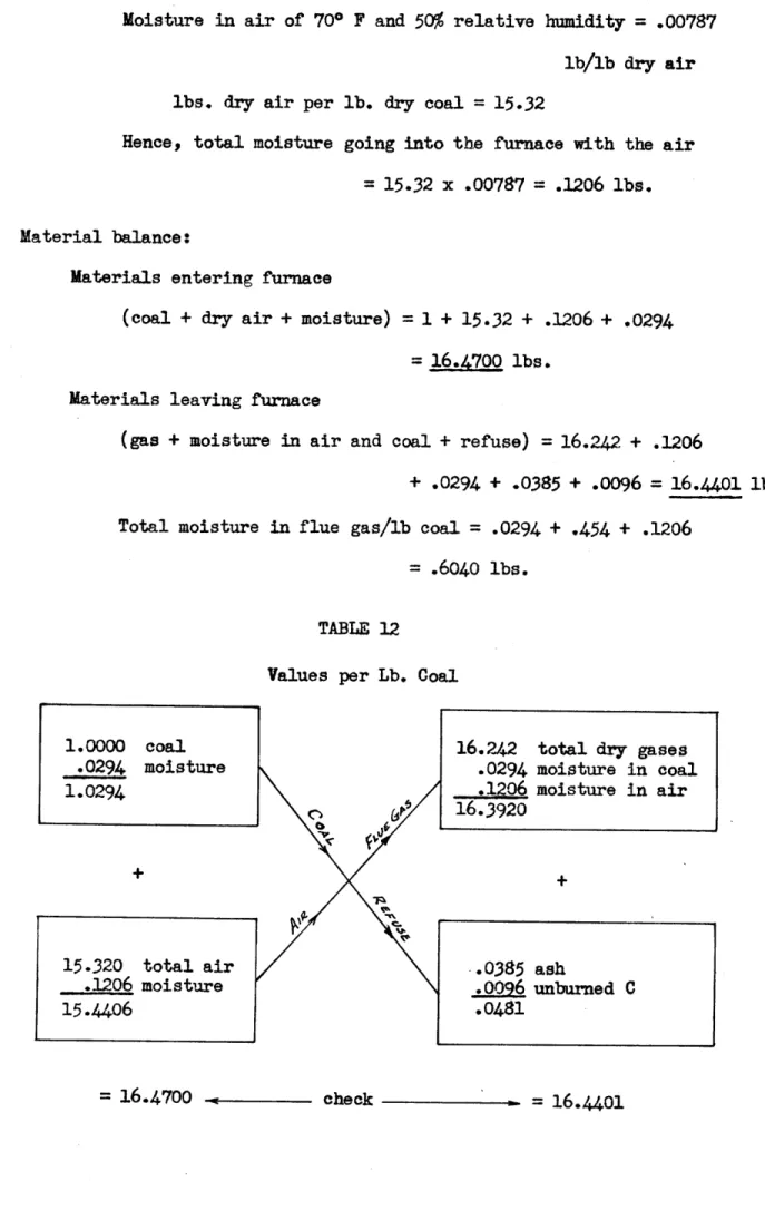
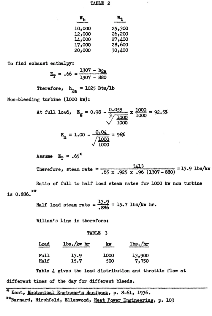
-4-To find exhaust enthalpy,
TABLE 2
Wb
10,000
12,000
14,000
17,000
20,000
Wt
25,300
26,200
27,400
28,600
30,400
1307 - h2a1307 - 880
Therefore,
h
=
1025 Btu/lb
Non-bleeding turbine (1000 kw)
*
At full load, E=
0.98 - 0.055X
=
92.5%g
3 1000
1000
V
1000
E=1.0
000
1000
Assume
ET=
.65*
Therefore, steam rate =
.65
x(30=13.9
lbs/kw hr.
.65 x .925 x .96 (1307
-880)
Ratio of full to half load steam rates for 1000 kw non turbine
is o.886.
Half load steam rate
=.886 =
15.7 lbs/kwhr.
Willan's Line is therefore:TABLE 3
Load
Full
Half
lbs./kw hr13.9
15.7
kw
1000
500
13,900
7,750
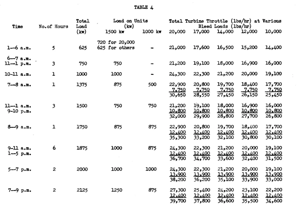
Table 4 gives the load distribution and throttle flow at different times of the day for different bleeds.
* Kent, Mechanical Engineer's Handbook, p. 8-61, 1936.
K -'-IL I-4--' -* -'-- -. -. tJj V I t- '- 4 -i-~ ---- C--*1 ~- -~
4'-4 1-'* V I t,1 V 1. 1 [IK.T~~
ti~2V
~
~-4iI
~ 44-14+ 'C 4- -~4-jj~v
'-Vt-.--. 4--~--l ~.14~2
-, ~-* --.7
Li J'_T-i
-4r -4--*. -t27
4t L~ -4-& -t4. 4~ 4- -'-4 -- t-4- t! 177 Lj t4 -I -i- -T4I
f4-
--
---{-4;
-Vt4-L~~ +~v~i.v- t 14ij
K
Ii~
4J2L
--1~
~TLjj
11 I I T . r I FTABLE 4
Time
1-6 a.m.
6-7 a.m.
11-1 p.m.
10-11
a.
m.
7-8
a.m.
11-1 a.m.
9-10
p.m.
8-9
a.m.
9-11 a.m.
1-5 p.m.
5-7
p.m.
7-9 p.m.No.of
Hours
5
3
1
1
3
1
6
2
2Total
Load
(kw)
Load on
Uni
(kw)
1500
kw
720 for 20,000
625
625 for others
750
1000
1375
1500
1750
1875
20002125
750
1000
875
750
875
1000
1000
ts Total Turbine Throttle (lbs/hr) at
Bleed Loads (lbs/hr) 1000 kw 20,000 17,000 14,000 12,000
Various
10,000
-21,000
17,600
16,500
15,200
14,400
- 21,200 19,100 18,00016,900
16,000 -24,300
22,300
21,200
20,000
19,100
500
750
875
875
1000
1250
875
22,900
7,f750
30,650
20,800
7,750
28,550
19,700
7,750
27,450
18,4007,750
26,150
17,700
7,750
25,450
21,200
19,100
18,000
16,900
16,000
10,800
10.800 10,800 1Q,0 104,80032,000
29,900
28,800
27,700
26,800
22,900
12,A-0035,300
24,300
12,40036,700
24,300
13,900
38,200 20,80012,400
33,200
22,300
12,4.00
34,700
22,300
13,90036,200
27,300
25,400
12,4Q 12,4.0039,700
37,800
19,700
12,*40032,100
21,200 12.40033,600
21,20013,900
35,100
24,200
12,400
36,600
18,400
12,40030,800
20,00012,4.00
32,400
20,000 13,90-33,900
23,100
12,400
35,500
17,700
12AQ00
30,100
19,100
12,400
31,500
19,100
13,900
33,000
22,200
12,4.00
34,600
%.03Average daily total throttle flow for different bleeds are listed in Table 5. TABLE 5 Total Daily Wb Ave. Throttle (lbs/hr) (lbs/hr) 20,000 30,400 17,000 28,100 14,000 27,000 12,000 25,800 10,000 25,000
The average yearly total throttle is computed according to the bleed load and is found to be 27,300 lbs/hr. Similarly, the annual average bleed flow is 14,500 lbs/hr.
The daily average throttle for each turbine is found as the sum for each, respectively, as obtained from Table 4 and then divided by 24 hours. The annual averages are easily computed.
Daily average throttle to 1000 kw turbine = 7600 lbs/hr. Annual average throttle to 1000 kw turbine = 7600 lbs/hr.
Hence, annual average throttle to 1500 kw turbine is (27,300 - 7600)
=
19,700 lbs/hr.Daily average throttle for 1500 kw turbine is listed in Table 6. TABLE 6 Wb Daily Average (lbs/hr) Throttle (lbs/hr) 20,000 22,800 17,000 20,500 14,000 19,400 12,000 18,200 10,000 17,400
Average annual steam from bleeder turbine to condenser =
19,500 - 14,500 = 5200 lbs/hr.
Average annual steam from non-bleeder unit to condenser =
7600 lbs/hr.
Average annual steam to the two condensers is 5200 + 7600 =
12,800 lbs/hr.
(22,200
-Maximum steam to the two condensers (from 7 to 9 p.m.)
=
10,000)
+12,400
=
24,600 lbs/hr.
Maximum steam to bleeder turbine (not at maximum load)
=
27,300 lbs/hr.
Maximum steam to 1000 kw turbine (not at maximum load) =
2.
Condenser Calculations
The designs are based on maximum flow from the turbines with
no steam bled. Average water temperature is assumed the same as that
existing during the summer (70* F).
This condition is on the safe side,
because if the temperature is below 70* F, a better vacuum results.
The statement of the problem with regard to ground level and condensing
water implies the adoption of a low level jet condenser, whose features
are a 50 terminal difference and the use of minimum injection water.
For this type of condenser, Miller and Holt recommend 28" Hg as the
optimum vacuum.
Temperature of condensate (at 2" Hg)
=
1010 F
Injection water temperature
=
70* F
Temperature of water leaving
960 F
Steam comes in
at h
2a
=
1025 Btu/lb, condenses at
2" Hg.
hwater
=
69 Btu/lb, cooling to 64 But/lb.
Condenser under 1500 kw turbine:
Wsteam (h2a
-
hwater)
=
Wwater
(96 - 70)
Injection required
=
20,000 (1025
-64)
=
746,000 lbs/hr
26
Gpm required
=
746,000
3= 1495
60
x 8.33Assume water required in air pump is 15% of that for
injec-tion.*
Water for air pump
=
.15 x 746,000
=
112,000 lbs/hr or
224 gpm.
From p. 218, we select No. 8 Westinghouse Leblanc Jet
Con-denser of 750,000 lbs/hr capacity with dimensions as given on p. 219.
Miller and Holt, Notes on Power Plant Design, p. 218.
,;Ibid., p. 220.
Steam inlet diameter
=
30 in.
2
Area
=
0.785(
)2
=
4.9 sq. ft.12
Injection water inlet diameter
=
9
in.
Area
=
0.785 (u)
=
.4
sq.
ft.
12
Quality at 2" Hg and 1032 Btu/lb is 0.922
Specific volume of steam at 2" Hg
=
339.2 cu ft/lb
Specific volume of steam in condenser
=
339.2 x .922
=
312 cu ft/lb
Hence, steam velocity
=
312 x 20,200
=
21,200 fpm,
60
x4.90
which is a reasonable value.
Injection water velocity
=
746,000
=
450 fpm., or 7.50 fps
62.4
x
60 x
.4
Water through removal pump
=
20,200 + 746,000
=
766,200 lbs/hr
or 1535 gpm
Condenser under 1000 kw
turbine:
Injection required
13,900 (1025
-6)
=
514,000
lbs/hr
26
Gpm required
=
*=
1030
As above, No. 7 Westinghouse Leblanc Jet Condenser of 600,000
lbs/hr capacity is selected.
Steam inlet diameter
=
30 in.
Area
![TABLE 11 4-,) 0 0*-0 4) Mr M +,4r H 0 2 PL '0 4-3 0) L4~~'o VA 4' 001,. C02 3.012 3.012 18.55' 19.00 .866 13.05 13.0 02 0 1.04+0 6.4]](https://thumb-eu.123doks.com/thumbv2/123doknet/14686983.560449/69.918.128.785.82.1094/table-mr-m-h-pl-l-va-c.webp)