DESIGN OF A
HIGH PERFORMANCE SOLAR SAIL SYSTEM
byKIM ERIC DREXLER
B.S., Massachusetts Institute of Technology
(1977)
SUBMITTED IN PARTIAL FULFILLMENT
OF
THE
REQUIREMENTS FOR THE
DEGREE OF
MASTER OF SCIENCE
at the
MASSACHUSETTS INSTITUTE OF TECHNOLOGY
MAY,
1979
.
Signature redacted
Signature of Author •.••••••••••.
111re,..-T""'r', . . . r-,...-.,-.-. • • • • • • • • • • •Department of Aer2nautics and A~t1:_on~utics, May
24, 1979
. .
Signature redacted
Cert1.f 1.ed
by.
I • • I • I I ... .,,. • • • , . , . . . .n
r.-.
I • I • • I • I • • • • • I • • • I • • • • • •• , · A A _ • , / ' ~
Thesis Supervisor
Signature redacted
Accepted
by ••
·~rctilfei ... ././. ... ; ... .
MASSACHUSETIS INSTITU~
Chairman' Department Committee
CF TECHNOLOGY
JUL 3 1979
HIGH PERFORMANCE SOLAR SAIL SYSTEM
by
KIM ERIC DREXLER
Submitted to the Department of Aeronautics and Astronautics,
on May 25, 1979 in partial fulfillment of the requirements
for the Degree of Master of Science
ABSTRACT
Fabrication of thin film reflecting elements in space
appears to make feasible solar sails with 20 to 80 times the
thrust-to-mass ratio of previously proposed, deployable,
plastic-film sails.
Relevant properties of thin film
mater-ials are reviewed.
A system for the production of thin film
reflecting elements in space is proposed.
A structural
con-cept suited to such sails is derived, and sail mass and sail
construction are considered.
Finally, the dynamics and
con-trol of such sails is examined.
Name and Title of Thesis Supervisor:
Walter Mark Hollister, Sc.D.
-Acknowledgements:
The author would like to thank Professors Hollister and
Miller of the Aeronautics and Astronautics Department for their
encouragement and aerospace perspective, and Dr. Frank Bachman
of the Lincoln Laboratories thin film facility and Professor
Rose of the Department of Materials Science and Engineering
for their review of the thin film aspects of this work.
Thanks
to the National Science Foundation for financial support.
Thanks are due to Christine Peterson for support, reading, and
criticism, and to the Student Information Processing Board text
processing project for giving her something legible to read.
Finally, thanks are due to the members of the Jet Propulsion
Laboratory solar sail design teams: had they not revived
page
Abstract
2
Acknowledgements
3
Table of Contents
4
Introduction
5
Chapter 1: Thin Films for Solar Sails
7
1.1 Criteria for choice of the reflecting material
7
1.2 Thin aluminum films for solar sails
8
1.3 Reinforcing films
15
1.4 Design of the thin film sheets
17
Chapter 2: The Film Sheet Production System
22
2.1 Objectives
22
-2.2 Choice of process concept
22
2.3 General considerations for subliming-substrate
24
processes
24
2.4 Process description
25
2.5 General features of the device
28
2.6 Subsystems and operations
30
2.7 Preliminary power and mass estimates
37
Chapter
3:
Solar Sail Structures
39
3.1 Tensioning concepts
39
3.2 Derivation of an efficient structural concept
40
3.3
The sail sheet structure
46
3.4
The rigging
55
3.5
The non-film mass of the sail
58
Chapter 4: Sail Construction
62
4.1 Strategy
62
4.2 The scaffolding
62
4.4 Sail structure packaging and deployment
67
4.5
Panel assembly
68
4.6 Assembly of panels to the sail structure
71
4.7
Sail release
72
Chapter
5:
Solar Sail Dynamics and Control
73
5.1 Mode 1 Dynamics and Control
73
5.2 Mode 2 Dynamics and Control
79
5.3
Mode 1/Mode 2 interconversion
80
5.4 Vibrations
81
Conclusions
83
-.
5-Introduction:
Plastic film materials chosen for use in deployable sails have masses around fifty times higher than those of thin, reflective aluminum films, on a per unit area basis. Since the acceleration of a solar sail is inversely proportional to its mass per unit area, successful exploitation of thin
film reflectors would result in solar sails of markedly improved performance. The delicacy of thin film materials appears to preclude successful launch and deployment (in the large areas needed for practical sails), necessitating their fabrication in space.
Use of thin metal films as reflectors for solar sails has been suggested several times in the past (Wiley, 1951; Tsu, 1959). A method for
fabricating such films in space has been proposed (Lippman, 1972), but experimental work with this method (which involved attempts at peeling the films directly from a solid substrate) failed to produce films less than
500 times thicker than films that the author has made, handled, and
suggests making in space.
The chapters that follow discuss the properties of thin films, the
design and manufacture of thin film elements suitable for use in sails, an
this is a design study, more effort has gone into the design and redesign of the various system elements than into detailed analysis of particular point designs. Each of the major system elements has undergone some four to six major revisions in the course of this work; in each of these revisions design and analysis were carried far enough to bring out most of the major problems and system features as a guide to further work. Many problems of analysis and optimization are suggested by the present work, and considerable review and analysis will be required to determine whether major problems have gone unnoticed, and whether the preliminary analysis of the problems that have been addressed is substantially correct. Some of these matters will be dealt with further in MIT Space Systems Laboratory
Report 5-79.
The concept described below is designed for high performance sails, large production rates, and low incremental production costs. In short,
these designs were developed with heavy sail utilization in mind.
While
the results are promising enough to suggest that heavy sail utilization may
eventually develop, considerably more work will be needed to determine the
appropriate tradeoffs for early, small-scale production of sails for
well-defined mission applications.
-7-Chapter 1: Thin Films for Solar Sails
1.1: Criteria for choice of the reflecting material
A reflecting material for a solar sail film must reflect light well in
thin layers, must not melt, evaporate, or otherwise degrade, and should be as low in mass as possible. While its strength is also of interest, this may be supplemented (at a penalty in mass) by a reinforcing film of a
stronger or otherwise superior material.
For a thin film to reflect well, it must have the free conduction electrons characteristic of metals (dielectric reflecting stacks are comparatively thick). In the thickness range under consideration (15 to
100 nm), most non-metallic materials are virtually transparent, although
some non-metallic conductors (e.g., carbon) have low enough transmissivity in thin film form to yield some thrust.
Absorption of light by the sail has undesirable effects beyond simple loss of thrust relative to a sail with higher reflectivity. For one, the absorbed light exerts a force directed radially from the sun. This
component of thrust is often a handicap for high-performance,
absorbed light heats the film, raising its equilibrium temperature in proportion to the fourth root of its absorptivity.
Other physical properties are also of importance. The thermal properties of a material place limits on how closely a sail built from it may approach the sun (the Icarus syndrome). To avoid evaporation or certain mechanical instabilities, the material must have a low vapor pressure (or a good protective coating) and an adequately high melting point. Low density metals are preferred to minimize the sail's mass. A
final consideration is the film's strength, toughness, and creep resistance, although these can be supplemented by reinforcement.
For a variety of reasons, this study will concentrate on aluminum as a reflecting material for the sails. It has high reflectivity, low density, a resaonable melting point, and a very low vapor pressure. Further, it has received extensive study in thin film form by various workers. The author has had enough experience with thin aluminum films to give him a measure of confidence in their ability to survive suitably delicate handling. Relevant examples from this experience will be cited fromm time to time. Still, other metals (magnesium?) could prove attractive. As will be seen in Chapter 5, however, the choice of a film material and thickness can be left open until very late in the sail development program itself with little impact on other system elements, and hence need scarcely be settled at this stage.
1.1: Thin aluminum films for solar sails
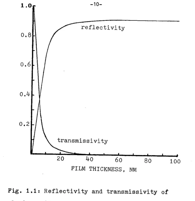
-9-Figure 1.1 plots the reflectivity and transmissivity of aluminum films
as a function of their thickness, for light with a wavelength of 600 nm. Contrary to what one would suppose from an intuition based on the concept of skin depth, reflectivity for short wavelengths falls off faster with decreasing film thickness than that for longer wavelengths, in good conductors (Barnes, 1931). Consequently, any aluminum film thick enough to reflect well in the visible wavelengths should reflect even better in the infrared, where roughly half of the sun's power output lies. Even in the visible wavelengths aluminum's reflectivity remains near its bulk value down to a thickness of 30 nm, and remains above 0.8 down to about 15 nm. (Note: at the Earth's distance from the sun, a "sail" consisting simply of a 15 nm aluminum film would accelerate at about 20 cm/s21)
The reflectivity of aluminum films varies with deposition conditions (Hass, 1961). Over a range of at least 303 to 4730K, reflectivity increases with decreasing substrate temperature. In the author's
experience, films deposited at 2500K were quite reflective. High deposition rates, near-normal vapor incidence, and a good vacuum all favor high reflectivity. In general, poor deposition conditions reduce reflectivity for the shorter wavelengths more than for for longer wavelengths, and thicker films are more sensitive to vapor incidence angle than are thin. Since most of the sun's power output is at comparatively long wavelengths, and since the films are to be quite thin, poor deposition conditions should not greatly affect sail performance. The device described in Chapter 2, however, should provide excellent deposition
reflectivity
0.8
0.6
o.4
0.2
transmissivity
20
o40
60
80
100
FILM THICKNESS, NM
Fig. 1.1: Reflectivity and transmissivity of
aluminum films as a function of their thickness.
To determine the forces on a solar sail accurately would require essentially complete knowledge of the film's optical properties. This study will simply approximate the reflectivity as 0.85 and the absorbtivity as 0.15, which are probably conservative values.
The emissivity (e) of an annealed, unbacked 98 nm aluminum film was reported as 0.05 at 4250
K, and 0.06 at 7250K (Boiko, 1973).
Assuming the pessimistically high value of solar absorptivity (a) given above yields an a/e of 3 to 2.5 for the film. Temperature calculations in this study will assume the still more pessimistic value of 5.2 (typical of bulk aluminum
-11-(Hunter, 1973)) for both surfaces of the sail, despite the likelihood of the aluminum film's being backed with a reinforcing layer of higher emissivity.
1.2.2: Film temperature
Under the worst-case assumption that it is normal to the sun's illumination, the equilibrium temperature of the film is
( OK
where Cr is the Stefan-Boltzmann constant, R is the distance from the sun in astronomical units (AU), and Pis the solar constant (1353 W/m2) at one
AU. Assuming the above value for a/e, the equilibrium temperature at one
AU is 4990K, rising to 7050K at one half AU. This is to be compared with
the 7250K temperature that aluminum films were subjected to in the above
experimental work on emissivities.
1.2.3: Agglomeration of low-melting films
Above some temperature, thin metal films fail by agglomeration. This occurs because thin films have an enormous ratio of surface to volume,
permitting them to substantially reduce their. surface energy by forming droplets. Above the melting point, the material rearranges swiftly, like a soap bubble bursting. At temperatures somewhat below the melting point, agglomeration into droplets occurs far more slowly, through surface
diffusion. Threshold temperatures for such processes typically scale with the melting temperature of the material, permitting one to draw analogies
between different material systems.
Thin films made from silver, with a melting point of 12350 agglomerate at less than 5000K (Seraphin, 1976): the analogous temperature for aluminum is a mere 3780K. Nevertheless, aluminum films have survived 15 minute
anneals at 6730K (Ferraglio, 1967), and two hour anneals at 7000K (Boiko,
1973). The latter reference presents data taken from films at 7250K, and
refers in its abstract to experiments at 9000K, within 33 degrees of aluminum's melting point. The reason for this pleasing discrepancy is the presence of an oxide layer on the aluminum, which armors the surface with a rigid, refractory skin, thereby inhibiting surface diffusion and preventing changes of shape.
The conclusion that the presence of a refractory surface layer inhibits agglomeration is supported by experiments in which silver films were rendered stable to hundreds of hours of annealing at 8130K by
s~ndwiching them between two layers of chromium oxide (Seraphin, 1976). Similar results have been reported for other materials, supporting the
notion that the special properties of the film formed by the natural oxidation of aluminum are unimportant to the stabilization of the film.
1.2.4: Creep
Since the films are to be hot and mounted under tension, creep is of concern. This leads one to consider the stress state inside a simple aluminum thin film. The interior of a small droplet will be in
-13-compression, because of its surface energy and the resulting force of surface tension. In like fashion, the interior of a thin film will be in compression (Hoffman, 1966), unless the mounting tension excecus its surface tension. Taking the surface tension of molten aluminum, 0.84 N/m (CRC Handbook of Chemistry and Physics, 52nd edition), as a lower bound on the surface tension of solid aluminum, 56 MPa (about 8,000 psi) is a lower
bound on the compressive stress in an untensioned 30 nm film.
Consider an oxide-coated film. to elongate it must not only break the oxide skin (which may be very strong), but must also create fresh, uncoated aluminum surface, requiring a force greater than surface tension to do so. To shrink, on the other hand, it must somehow crush or destroy the oxide surface, which its clearly cannot do. In fact, "shrinkage" would manifest itself as agglomeration, which was discussed above. In designs where the tensioning forces are less than surface tension, creep should be no problem, even in ordinarily creep-prone materials.
1.2.6: Mechanical properties
The strengths of a variety of thin metal films and thicker vapor deposited sheets have been measured experimentally. Metals in thin films have mechanical properties differing from those of the bulk material,
because of the close proximity of all parts of the film to the surface.
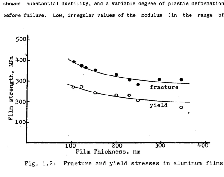
Figure 1.2 summarizes data from Millillo, 1969,
on the strength of
aluminum films as a function of their thickness at ordinary temperatures.
NIte that the yield and fracture stresses increase as the film gets
thinner;
this behavior is typical of other metals as well.
Aluminum films
showed substantial ductility, and a variable degree of plastic deformation before failure. Low, irregular values of the modulus (in the range of
500
0400
'0300
20 fracture -, 01200-yield02200
r%
4 100 100200
360
400
Film Thickness, nm
Fig. 1.2:
Fracture and yield stresses
-in aluminum films
10,000 to 20,000 MPa) were reported for the same set of films.
Gold films less than 50 nm thick exhibit no plastic strain before fracture (Hoffman, 1966), and hence presumably lose much of their tear resistance. This loss of plasticity is believed to result from the pinning of dislocations by the surface; consequently, other metals should show the same phenomenon below some thickness. The scarcity of data in the literature on the strength of films much below 60 nm thick supports this notion. In the author's limited and qualitative experience, aluminum films
seemed to become disproportionately more fragile as they became thinner,
below an estimated thickness of 60 nm.
-15-1.3: Reinforcing films
Aluminum films of the minimum thickness required for essentially full reflectivity may prove too weak to support the stresses imposed on them during fabrication and operations, or may creep under load at elevated temperatures. If so, it seems natural to strengthen them, not by adding further aluminum, but by adding a reinforcing film of a stronger, more refractory material.
1.3.1: Design considerations
A good reinforcing film should be strong, light, and easy to deposit.
It need not be chemically compatible with aluminum, since a few nanometers of some other material can serve as a barrier to diffusion. A reinforcing
film is apt to have such a high modulus that it will act as the sole load bearing element in the composite film. The aluminum film could help contribute tear resistance, however.
The use of a metal as a reinforcing film should reduce the amount of aluminum needed to give good reflectance. Some metals, such as nickel, may
reflect well enough to be of interest by themselves.
Ceramics are among the strongest materials, and many have been prepared in thin film form. Unfortunately, there has been little interest
in unbacked thin films of most ceramics, and still less interest in
measuring their mechanical properties. Thin, unbacked films of various
targets for nuclear studies, as filters transparent to energetic photons but opaque to visible light, and as micro-samples for basic research on metals. Ceramics, unfortunately, are generally not elemental, lack special optical properties in thin, unbacked layers, and are not metals. Nevertheless, the strength of certain ceramics in bulk form, the general tendency of thin films to be strong, and various information in the literature all suggest that some of these materials may make excellent reinforcing films. Many structural metals and ceramics could have been mentioned as candidate materials, but data is sparse.
1.3.2: Candidate materials
Films of pure titanium some 250 to 2,000 nm thick were found to have strengths of 460 to 620 MPa (Pickhardt, 1977), while vapor deposited foils
of Ti-6A1-4V some 40,000 to 2000,000 nm thick had tensile strengths of 970
to 1,200 MPa, and met aerospace materials specifications for use in
honeycomb structures. (Smith, 1970).
Titanium has enough strength and
temperature tolerance to make it an attractive choice as a reinforcing
film.
Unbacked filks 52 nm thick and 0.8 om across are reported (Rustgi,
1965).
The strength of nickel films exoeeds 2,000 MPa at thicknesses of 70
nm
or less, dropping to 1,500 lPa on annealing (Hoffman,
1966).
Nickel's
density is a disadvantage for use in sails of the highest performance, but
should prove aooeptable for bulk transport sails.
Silicon monoxide is a popular thin film material with many uses.
On
-17-coatings, and have demonstrated their stability in the space environment. Unbacked aluminum thin films with SiO coatings have been made for use in space (Hunter, 1973). Mounted on fine metal meshes, unbacked SiO films as thin as 2.5 nm have found use as specimen supports in electron microscopy (Hall, 1966); such films are described as having "great strength," and are so stable at high temperatures that they may be cleaned by passing them rapidly through a blue gas flame. Since SiO is easy to evaporate, is refractory (melting point
=
19700K), has a low density (2.13 gm/cm3), isapparently of high strength in extremely thin film form, and is of known
space compatibility, it shows promise as a reinforcing film material.
Vapor deposited boron films have strengths of 620 MPa (Beecher, 1967). Since it is light and refractory, boron may prove desirable as a
reinforcing material.
Carbon forms amorphous films of "exceptional strength;" those used in
electron microscopy are made as thin as
4
nm (Hall, 1966).
Since carbon is
strong,
light, refractory, and easy to deposit, it is a promising material
for reinforcing films.
1.4: Design of the thin film sheets
1.4.1: Shape and size
For a wide variety of reasons, the sail will not be one big piece of
film, but rather many smaller sheets mounted on a structure. Since the
fabrication device will produce strips, natural ohoiaes for the shapes of
the sheets include long strips, shorter reotangles or squares out from the
strips, and triangles cut from the strips. These sheets must be tensioned, and should be plane. Since a triangular sheet will be plane if tensioned at its corners, and since triangular sheets will fit well into a fully triangulated structure, they will be used as a basis for further design work here.
The width of the strip will determine the altitudes of the triangular sheets. The fabrication system described in the next chapter produces strips one meter wide, yielding equilateral triangles 1.15 meters on a side and 0.575 square meters in area.
1.4.2: Tear-resistant sheet design
Tears are a critical concern in the use of thin films for solar sails. While even sheets of extremely thin material have adequate strength to support the loads expected during fabrication and operations in the absence of stress concentrations, the inevitability of manufacturing flaws and micrometeoroid damage makes this a small comfort. While subjecting the film to only a small fraction of its fracture stress will leave small flaws stable, on large thin sheets exposed to space for prolonged periods, meteoroid damage is still apt to start tears. A means of limiting the
spread of tears would be desirable, as it would allow a thinner sheet to
tolerate greater damage without failure.
The most obvious method of limiting tears is to mount the film on a
supporting mesh. Indeed, since thin aluminum and gold films have flown
into space so mounted on several occasions, this may be considered a proven
mthod (Hunter, 1973; Hemenway, 1975).
However, differing coefficients of
-19-thermal expansion and differing temperature between the mesh and the film are apt to make the film become slack and lose its flatness, or become taut and possibly tear. Further, the mesh adds mass to the sail, and, because it must be fabricated, transported into space, and attached to the film, adds cost as well. Still, with modest sacrifices in performance from slackness and added mass, a mesh support will apparently work. This approach has the potential advantage, moreover, of reducing the film stresses to virtually zero.
As will be seen in Chapter 3, the operational stress in even quite high performance sail films is a factor of several hundred below their fracture stress. Since the problem is not so much the stress as the propagation of tears, a natural approach to tear-stopping is to subdivide the film, converting it from a continuous sheet to a redundant network of small, load-bearing elements. In such a structure, a large manufacturing flaw or a grazing micrometeoroid impact is free to initiate a tear---but the tear will cause the failure, not of an entire sheet, but of a small piece of film, perhaps 25 square millimeters in area.
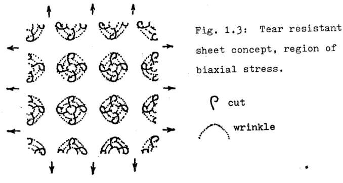
Figure 1.3 illustrates how a pattern of cuts and wrinkles can de-tension areas of film to isolate stress in smaller regions. Each wrinkled region is fabricated with enough extra material to avoid being stretched flat as the film is tensioned. Stress isolation is aided by slits extending perpendicular to the boundaries. These slits are
terminated at their stress bearing ends in a way that avoids initiation of
tears.
As may be seen,
a
tear in any region
will propagate
into
a
de-tensioned
region
and
stop there, limiting damage to a single element.
able to take both the redistributed and the transient loads from element
%
06:."Fig. 1.3:
Tear resistant
sheet concept, region of
biaxial stress.
4:,cut
wrinkle
failures.
Figure 1.4 shows how tears can be blocked in a region of essentially
uniaxial tension,
like that near the corner of a triangle.
Slits, again
terminated so as to avoid initiating tears, divide the film into parallel
load-sharing tapes.
Not shown is an alternative pattern for the main
sheet, with hexagonal elements and triangular detensioned regions.
Such a
lo..O....--C
Fig. 1.4: Cuts in a region of uniaxial
stress.
-.
21-While the film sheets are quite large, the small load-bearing elements are of a size similar to that of tensile test specimens made in the laboratory.
This approach to tear resistance appears superior to that of mounting the films on a metal mesh. It involves the fabrication of no additional elements, and the addition of no extra mass. By taking advantage of the
natural strength of the films, it avoids slackness due to differential expansion and yields a flatter sail.
While the above describes an attractive and apparently feasib.3 approach to the design of the film elements, a variety of questions remain regarding the detailed design. Should the film have a positive, negative, or zero curvature, in the metric sense? How should stressed and unstressed regions be distributed? Need the edges of the triangles be scalloped to avoid wrinkles, or are wrinkles acceptable, or is there another way of avoiding or controlling them? The answers to these questions will have only a small impact on final sail performance, primarily through their effect on the variance of the sail surface angle, hence a more detailed
Chapter 2: The Film Sheet Production System
2.1: Objectives
Since vapor deposition builds up thin sheets of material atom by atom (as opposed to rolling them down from ingots), films can be made very thin. The technology of applying aluminum coatings to materials in quantity is well established (decorative papers, for example). A lower limit on
unbacked film thickness may well be set by the breakage of delicate films during handling. For this reason, minimizing the stresses applied to the
film is an important design objective.
Other design objectives are straightforward, if the system is to be well adapted for large-scale production. The system should have low mass,
a high production rate, and minimal complexity. The author has examined many candidate approaches to meeting these objectives.
2.2: Choice of process concept
Many approaches to film fabrication may be
considered.
Most
-23-Unfortunately, unavoidable adhesive forces prevent suitably thin films from peeling without tearing, rendering this sort of process unattractive.
The film may be deposited on a solid, then the solid may be dissolved so as to leave the film floating on the solvent, from which it may be removed. This approach works (for small areas), and is widely used in the laboratory. It has the disadvantage, however, of requiring both a solid substance and a solvent in the process, and of involving both washing and drying of the film. Simpler, related processes include deposition of the film on a solid sheet which is then melted and evaporated, or deposition of the film on a liquid surface from which it is peeled before drying.
Unfortunately, removing large areas of film from a liquid surface and drying them would probably prove difficult. In the author's experience with solid dissolution and liquid substrate processes,. surface tension forces proved able to enlarge tears, once the liquid film ceased bridging them. Since the preferred film sheet design has many cuts for stress relief, and since occasional flaws and tears would be inevitable in any case, this poses a major problem. Further, removing a film sheet from a liquid surface requires a support (such as a wire mesh); removing the film from this support also poses problems. For these reasons, processes which require separation of film sheets from a liquid will not be considered further here.
This leaves processes involving deposition of a film on a solid, followed by sublimation of the solid. These have the advantage of removing
the substrate molecule by molecule, a process which is inherently virtually
force free.
2.3: General considerations for subliming-substrate processes
To minimize the thermal input required to heat and sublime the substrate, it should be made as thin as possible. Since the substrate strips will be fairly wide, the organic substance must be reinforced or supported by a stronger material. Invar seems a reasonable choice to minimize thermal distortion of the substrate belt during thermal cycling.
To produce reasonably smooth films with a large component of specular reflection, the substrate must be reasonably smooth. Production of the prefered film sheet design further requires that the substrate be textured, to increase the area of the film in areas to be 'relieved of stress. Finally, since the film itself will be impermeable, consideration must be given to the escape of subliming vapor.
One approach to substrate fabrication is to coat a metal screen with a sublimable wax, and to shape its surface by pressing it against a polished,
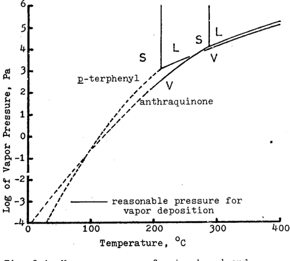
textured roller. The holes in the mesh permit escape of the subliming vapor. This approach requires the organic substance to have forgiving mechanical properties; a stable hydrocarbon wax, g-terphenyl (Bennet, 1956), might serve (see Fig. 2.1 for its vapor pressure curve). Control of the substrate's surface finish might pose a problem, but many alternatives exist. Although the fabrication process is comparatively complex, the author has carried this approach far enough to produce a seemingly workable design.
Another approach to substrate fabrication starts with a smooth,
textured metal foil, then coats it with a thin parting layer of sublimable
6
00
5S
40
L
S
V
p-terphenyl
-2V
,'/anthraquinone
0 0 4-2W-3 reasonable pressure for
vapor deposition
0 100 200 300 400
0 a0
T empera-tur e, C
Fig. 2.1: Vapor
pressure
of p-terphenyl and
anthraquinone (Fritz, 1968; Kirk-Othmer, 1978).
thick are commonly laid sown. Such layers might be made to bridge pores in the foil, permitting escape of subliming vapors through the back of the substrate. Alternatively, the substance can be laid down by vapor deposition. In this case, it may be simplest for the subliming vapor to escape through holes in the film itself. This process is attractive, since vapor deposition is well understood, simple, and able to lay down very thin layers if need be. It has been selected here as a basis for further work.
2.4:
Process description
below. The operations described occur in sequence to each segment of the metal foil belt as it travels clockwise around the loop. This section
presents an overview of the process; the operationswill be described in more detail later.
The process starts as the foil belt enters the enclosure at the top of the diagram, and comes into contact with a cool roller. This cools the belt to about 00C, and carries it through a deposition chamber where it is
coated with about a micron of a sublimable substance (such as anthraquinone, among many poibilities. See Fig. 2.1 for vapor pressure curve) amerges from this enclosure into the vacuum of space prepared for deposition of the film.
Next, it traverses a distance in vacuum,.passing under a series of vapor sources. These lay down films of material to build up the sail film. Then, it passes between two rollers which cut the film to separate it into sheets and to complete the stress relief pattern. At this point, the film sheets are ready to be mounted and freed from the substrate.
A screen belt, supported by ribs, is brought into contact with the
first belt as both enter the sublimation chamber through a set of seals. The screen belt bears small metal foil spring clusters with hot melt glue
on their tips. As these heat up inside the chamber, they fuse to the corners of the film sheets, mounting them. Inside the chamber, the foil
belt is brought to sublimation temperature by contact with a heated roller.
It then passes in front of a series of infrared lamps which heat it further
to sublime the material away.
The subliming vapors escape tnrough the cuts
made earlier; the pressure differential across the film is supported by the
-27-finished film
I
Bseal region
I SI
U I Ssubli
lamp
compressor--mation
enclosure
3
II
I II
I II
a g I II
aI
]
I
I
'}
-10 0 I'IWD
do IF a - Ndparting layer
vapor source
cool roller
enclosure
prepared foil belt
- >-
vapor source for
film deposition
cutting roller
seal region
foil spring loader
heated roller
screen belt
liquify the vapor for return to the deposition chamber.
Finally,
the belts exit through a series of seals,
and
are
decompressed gradually to let the remaining vapor escape.
The film sheets,
now mounted on the foil spring clusters, are carried off as the belts separate outside the chamber. The sheets are then assembled into panels (see Chapter 4); the belts re-enter the cycle.
2.5: General features of the device
2.5.1: Size
Although a considerably wider device could be accommodated in the Shuttle payload bay, the one described here is sized for strips only one meter wide. While wider strips would yield a higher performance sail (due
to a reduction in the number of spring clusters and so forth per square
meter of reflecting area), standard cost estimation methods suggest a higher DDT&E cost, and a higher cost for sail manufacture. The one meter strip size strikes a rough balance between these conflicting consideraions, but the choice remains somewhat arbitrary in the absence of detailed
analysis.
As Fig. 2.2 shows, the device is some 12 meters long, well within the
18 meter length of the Shuttle payload bay. This length is priiarily
determined by the swiftness of substrate sublimation and the belt speed.-29-conservative.
2.5.2: Belt speed
Increasing the belt speed tends to increase device productivity per
unit mass, but at some point leads to mechanical difficulties. A variety of industrial processes run belts, material webs, and chain drives at
speeds well over two meters per second. One meter per second will be
assumed in the following, yielding a device output of over 20,000,000
square meters (20 square kilometers) per year.
2.5.3: The sublimable substance
Determining the optimal properties of the sublimable substance involves a number of tradeoffs. Many materials have reasonable vapor pressure curves and other properties. For the sake of concreteness, use of anthraquinone will be assumed here. It has a triple point at about 100 Torr and 2860C, and does not decompose appreciably until much higher temperatures. It is relatively non-toxic, easing precautions in testing of the device (Kirk-Othmer, 1978).
2.5.4: Utilities
The device will have
onboard
electric
power
supplies
from
photovoltaics, or may be plugged into an orbiting yower module. It will be
equipped with a radiator and coolant loop. Attitude control is to be
provided by a larger platform of which the device would be a component.
2.6: Subsystems and operations
2.6.1: The foil belt
The foil belt is conceived of as a 25 micron thick sheet of Invar alloy. The only major disadvantage of thicker foils would be the increased power and radiator requirements arising from the greater amount of metal to be heated and cooled in each cycle. The foil may be made thicker near the edges with little penalty.
In patches corresponding to stress-relieved areas of the film, the foil must be textured. This texture consists of concentric ridges, 0.4 mm from peak to peak, with the valleys 10 microns below the peaks. This suffices to produce the stress relief bulges in the film. The surface in the textured regions, as elswhere, should be as smooth as possible.
Fabrication of such a belt might involve electron beam or laser welding to join a strip of foil into a belt, and perhaps to add thicker material at the edge. The welds could then be ground smooth. The belt could be flattened by stretching, rolling, and annealing operations, and could be textured by stamping. The smooth surface could be imparted by polishing, perhaps after deposition of a hard alloy able to take a high polish.
-31-The foil belt begins its cycle when it enters the deposition chamber. Inside, it makes thermal contact with a cool roller for about a second. Good thermal contact may be ensured by surfacing the roller with a soft material, such as rubber. The roller is cooled by circulating fluid from the coolant loop down its axis. Efficient transfer of heat may be ensured
by making the interior a heat pipe.
Vapor sources deposit a micron of anthraquinone on the foil belt while it is in contact with the roller (The one micron figure is fairly arbitrary, experimental work should be done here). This vapor emerges in well-directed jets from electrically heated, liquid fed evaporators, and impinges on a 00C surface. A small fraction of the vapor will miss the strip or fail to condense on impact. This remainder forms a low pressure background atmosphere in the chamber, which must be controlled.
The first step toward control is to surround the evaporators and belt with heated baffles, leaving only small clearances for the moving belt and roller. Thus, most molecules entering the atmosphere leave again by condensing on the belt, where they belong originally. Only a small fraction will escape.
By heating the chamber walls as well, buildup of condensate on these
surfaces is prevented. Only the roller, which must be cool to serve its function, poses a problem in this regard, and it can be kept adequately clean with fixed, heated scrapers. The traces of vapor escaping the chamber can be kept from impinging on the rest of the device by properly
placed baffles.
Since the anthraquinone layer is thin, the substrate surface will be a
good replica of the foil surface.
Smooth surfaces have been observed in
organic films a few microns thick.
2.6.3 Film deposition
The belt then passes under a series of vapor sources which deposit the film stack, sun-side layer first. When it emerges from the deposition chamber, the substrate's vapor pressure is around 0.0001 Pa (a reasonable pressure for vapor deposition). Further, the first layer of film to be deposited blankets the substrate, preventing further evaporation. Since the system is open to space, the vacuum is then excellent. Also, the substrate is cold, the film is thin, the deposition rate is high, and deposition is at nearly normal incidence. For these reasons, film quality should be high, limited mainly by substrate smoothness.
Vapor source design will not be dealt with in any detail here. It should be noted, however, that a wide variety of evaporators for a wide variety of materials have been used on Earth (Maissel, 1970). The major problem with evaporators on Earth is generally crucible corrosion, which may be avoided in space by levitation melting. This should permit evaporation in insulated, refractory boxes with apertures for escape of the vapors (Drexler, 1976). Such sources should be quite efficient, and should
permit comparatively good control of the vapor flux distribution. The
following will assume 20% efficiency of energy use in evaporation, and 20% loss of materials. These assumptions are probably conservative. It
should be noted that waste heat from the evaporators will radiate directly
to space, adding no burden to the cooling system.
-33-is
spatial:
the more uniform
the thicknessdstribut on across the
width of the strip, the more evaporators needed, introducing a design tradeoff. Also, deposition of thicker reinforcing films only where they are needed (around the corners of the film triangles, as opposed to all along the sides of the strip) is desirable for sails of the highest performance, but requires modulation of the vapor flux. The other dimension is temporal: to obtain a uniform film thickness as time passes requires either very stable vapor sources, or active monitoring and control of the deposition rate. Adequate control of film thickness (for ordinary sails at least) appears to present no special problems, with appropriate equipment and instrumentation.Since vaporizing aluminum takes roughly 13,000 J/gm (CRC Handbook of Chemistry and Physics, 52nd edition), condensation of a 100 nm film will deposit about 3,500 J/m2 of heat in the substrate.
If the substrate is a
25 micron thick Invar foil with a heat capacity typical of iron or nickel
(0.44 J/gm-OC), its temperature will rise by 400C.
This poses no problem, since the film inhibits substrate evaporation. This calculation neglects radiative heat transfer, which should be fairly small since the aluminum film quickly becomes thick enough to reflect infrared light. If necessary, a thicker substrate could be used, yielding a lower temperature rise.
Some of the vapor will miss the substrate, as assumed above. In most
vacuum systems, this poses a cleaning problem since the vapor deposits on
various surfaces of the device. In this system, the substrate shadows most
of the rest of the system (vapor deposition is a line-of-sight process).
Vapor spillover dissipates iinto space. The few areas not so protected can
be shielded by replaceable baffles.
As with all proposed thin film
processes,
this one will require experimental verification. However, the close analogy to present commercial vapor deposition processes and the considerable freedom of design suggest minimal problems with the actual deposition of the film.2.6.4: Cutting
Once the film is deposited, its continuity must be broken to separate it into sheets and to make the cuts proposed for stress relief. Further, the pattern of breaks must be in register with the texture on the belt. Finally, the belt itself must not be damaged.
Film continuity can be broken by running the belt between two rollers, one bearing cutters which press through the film and into the organic layer. To keep the patterns in register, this roller can have a slightly variable radius, under active control. To avoid damage to the belt, the cutters should be of an elastic material considerably softer than steel, perhaps a hard plastic.
2.6.5: The screen belt
Inside the sublimation chamber, the thin film will be supported by a screen belt. This is a belt with a screen surface supported by metal ribs. It is kept at the temperature of the sublimation chamber and is brought
into contact with the film at the entrance to the sublimation chamber.
A device loads foil spring clusters (see Fig. 2.3) onto clips on the
-35-contact, these foil springs are aligned with the corners of the film triangles, and their tips, coated with hot melt glue, rest lightly against
foil
base
handling hole
foil spring
(folded packet)
Fig, 2.3: Foil spring cluster.
the film. 2.6.5: Transfers to and from vacuum
Seals of some sort must be provided to prevent excessive escape of vapor from the sublimation chamber. In this task, the condensabilty of anthraquinone can be used to advantage. On the incoming side, a series of baffles and seals can cut the leak rate from the chamber to the central region of the seal to less than 10 gm/sec (equivalent to the leakage through a hole about a centimeter square). The cool substrate belt can then condense this material before it escapes through the rest of the seal and carry it back into the chamber. The last bits of vapor can be scavenged in cold traps and periodically recovered.
On the outgoing side, the substrate belt is hot, so this trick cannot be used. Instead, the two belts pass through a series of small clearances and chambers, with each chamber at a progressively lower pressure. Vapor could be recovered from these chambers with pumps, but use of a chilled belt to condense and carry material back into the sublimation chamber seems a better solution. Again, cold traps can scavenge the last of the vapor.
2.6.6:
Freeing the filmConditions in the sublimation chamber are near the triple point of the sublimable substance. Under these conditions, the substance can be sublimed, compressed slightly, and recondensed to a liquid. This greatly facilitates handling.
As the belt enters the chamber, material will condense on it in a thin, dense layer until its temperature rises far enough to prevent further condensation. The belt is then brought into contact with a heated roller, which brings it to a high enough temperature to sublime the condensate and begin sublimation of the parting layer. At this point the hot melt glue fuses the foil springs to the film sheet corners.
In the sublimation process, heat may be input to the substrate by infrared lamps, as shown in Fig. 2.2, or by circulating heated vapor against the underside of the belt. Vapor escapes through the breaks in the film (special breaks may be made for.this purpose, if need be), and is recovered by compression and condensation.
At this point, the integrity of the film becomes of concern, since it is being subjected to a pressure differential and is now unbacked over increasing areas. Since the anthraquinone is assumed to be one micron thick, and since it expands by a factor of 3,000 on vaporization, a 3 mm thick slab of gas must be forced through the cuts. At a velocity of one meter per second, this would take three seconds if the breaks opened as
little as
0.001
of the area.
To support the film, the entire substrate belt is pressed gently against the screen belt by a small pressure differential. The mesh screen,
-37-in turn, is supported by a track. Two issues arise: whether the film will tolerate contact with the screen, and whether the pressure differential across the film will enlarge tears. To answer such questions, the author fabricated and tested films with an estimated thickness of 40 nm. These films tolerated sliding contact with a blunt metal object. With V-shaped tears about one millimeter in size and sparse (about 0.5 cm spacing) supports, they tolerated exposure to 6creams of air at normal incidence with speeds in excess of one meter per second. The tears did not enlarge.
For the sake of conservatism, the sublimation chamber is designed to be much longer than three meters, and the seals at the exit point will lower the vapor's pressure quite gradually. These measures make the forces exerted on the film in the sublimation chamber far less than those successfully withstood in the experiment just described. For this reason, no difficulties seem likely in freeing films of the thickness considered.
After exit from the chamber, the foil spring clusters, now carrying the film sheets, are transferred to a conveyor and taken away to the panel assembly device. A concept for such a device is presented in Chapter 4.
2.7: Preliminary power and mass estimates
A crude estimate of the system's mass is desirable to permit a
preliminary estimate of costs. Power consumption may be used to estimate power system mass. Heating the belt from OC to 2900C and subliming the
anthraquinone takes about 26 kW.
If the exit seal system must recover 10
ga/s and sublime it again, this adds about 5 kW. At the assumed 20%
10 kW will be allowed for heat losses and miscellaneous uses (motors, compressors, substrate deposition, etc.) Total power consumption is thus about 62 kW for a one square meter per second system. At 15 kg/kW, this amounts to 930 kg of power system.
A crude estimate of the structural mass may be made by assuming use of
aluminum honeycomb with an areal mass density of 7 kg/m2 (this should give a compressive strength of at least 300,000 N/m). A generous estimate of
the mass of structure needed is that of a 1.5 m diameter tube of this material 12 meters long, plus about 20 square meters of structure of equivalent areal density in the rollers. This comes to about 540 kg.
About 41 kW of waste heat must be radiated. Assuming a 3000K radiator temperature and 10 kg/m2 of radiating area adds 1,000 kg. Allowing 530 kg
for multiply redundant motors, evaporators, compressors, and so forth brings the estimated total mass to 3,000 kg.
-39-Chapter 3:
Solar Sail Structures
3.1:
Tensioning Concepts
A solar sail structure must hold a large area of reflecting material
in tension,
must transfer normal forces from this area to a payload, and
must be able to hold the reflecting material at various angles to the sun,
and to
change this orientation on command.
In addition, it should be of
low mass, easy to construct, and capable of surviving long exposure to
space. Many solutions to this problem have been proposed.
Conceptually,
the simplest means for tensioning the sail is
a
structure more or less like a kite, with stay-stiffened compression members
as the sticks. This approach was explored in studies sponsored by JPL, in
connection with the design of a plastic-film sail system (JPL,
1976).
While tke mass of the compression members in this design was a small
fraction of the sail mass, it was still on the order of a gram per square
meter.
Since thin film technology seems to permit reflectors of some 0.04
to 0.27 gm/m
2, designs incorporating such compression members would realize
only a fraction of the thin film sail's potential performance.
used to oppose the tension in the plane of the reflecting material. (This tension must exist to prevent the surface from ballooning out under light pressure; parachute-style sails have been shown to be unstable (Villers,
1960)) Candidate forces include electrostatic, magnetic, and centrifugal.
An electrostatically tensioned sail must have a large charge to cause adequate self-repulsion between different parts of the sail. Since space is filled with a conductive plasma, however, the charge would tend to be neutralized swiftly. JPL examined and rejected this option (JPL, 1976).
A ring of current carried by a superconductor would repel itself, and
could be used to magnetically tension a circular sail. To adequately tension a one kilometer sail would require on the order of 10,000 amperes of current. If the system were allowed to add a mass of 0.1 gm/m2 to the sail, the conductor, insulation, and refrigeration system would have to meet a mass budget of only 25 gm/m, a low value. Still, because of economies of scale, magnetic tensioning could conceivably prove desirable for very large sails.
Centrifugal force is straightforward, and can clearly tension a rotating sheet of material. It has been chosen for the design presented here. The following sections will derive an efficient structural concept based on centrifugal tensioning, and will briefly examine a specific structural design.
3.2: Derivation of an efficient structural concept
The farther a piece of sail material is from the axis of rotation, the
-41-Hence there is an incentive to make spinning sails approximate disks.
The preferred design in the recent JPL-sponsored study was the Heliogyro: a centrifugally tensioned, centrifugally stiffened structure with reflectors deployed in long, narrow blades (Friedman, 1978). While such blades are structurally inefficient, the study's groundrules led to a requirement for the use of plastic film sail materials, the mass of which rendered structural efficiency a secondary consideration. Further, since the sail was to be deployable, the ease of deploying the blades from rolls together with a clever attitude control scheme involving blade pitch made this option attractive. At an earlier stage of this study (JPL, 1976), a rotating disk-shaped sail was considered and rejected, because of deficiencies in attitude control and other problems not applicable to the design considered here. It should be noted that the present design differs from the Heliogyro in being tensioned but not stiffened by centrifugal force.
The shape of a tension structure under load typically depends on the ratio of various forces in the system, in this case, those arising from light pressure and from rotation. For this reason, the ratio of the light pressure force per unit area to the centrifugal force per unit area is a parameter of interest. Call it "E."
In a spinning, disk-shaped membrane, the radial component of tension must fall to zero at the edge, by continuity. In typical designs, membrane
tension will be at a maximum towards the center if the sail. The radial
force per unit area, assuming constant mass per unit area, varies linearly
with radius, falling to zero at the center.
The force of light pressure
force on mass element
Fig. 3.1:
Combined centrifugal and light pressure forces.
that shown in figure 3.1.
Figure 3.2 presents a series of sketches of idealized solar sail designs, leading from a primitive concept to a simplified version of the concept presented in more detail below. All of them represent cross
sections along the axis of the sail, with the sail sheet, payload, and connecting tension menbers shown. To aid the reader's intuition, the drawings are oriented so that the force of light pressure is downwards; it may be modeled by a uniform gravitational force on the sheet. The inertia of the payload may then be modeled as a fixed attachement point from which the sail is "hung." All tension members are assumed to have negligable mass, and the shape of the sail is then sketched as it would be under the effect of "gravity" and centrifugal force.
Figure 3.2 (A) illustrates the simplest case, in which the centrifugal force is very great compared to "gravity," making the sail a taut, flat disk, "supported" at its center by the payload. Figure 3.2 (B) illustrates
the deformation of the sail for a small value of E;
the center of the sail
-43-Fig. 3.2: A series of solar sail designs, in cross
section.
(B)
payload
tension member
sail surface
(D)
(E)
(F)
(A)
(C)
An(E)
Fig. 3.2, continued.
(G)
-N - I a b - LF
--(H)
Fig.
3.3:
Forces on a section of the sail near
the edge.
1Force from shrc
2 Linking tensior
3
Force in plane
4
Force of light
5
Centrifugal
for
)ud
line
imember force
of sail
pressure
'ce
2
S
:3
I
offset
%A.-0-45-approximately E radians. Figure 3.2 (C) illustrates that the payload may
be moved in front of the sail and connected to it by a tension member with
the same result.
These sail designs are not very flat (for reasonable values of E) and have stong stress concentrations at their centers. This may be alleviated, as in (D), by adding tension members to support the sail sheet at more
points. Figure 3.2 (E) shows this process continued, yielding a still flatter sail for a given value of the parameter E. As may be seen in the sketch, the sail sheet sags more at the edge, where the sheet's tension is low, than near the center, where it is high. Figure 3.2 (F) shows how this excessive bagging at the edge of the sail may be eliminated by leaving the edges as free-hanging flaps. Note that the edge flap angle remains approximately E radians, regardless of inner structure.
The sail shown in (F) suffers from an excess of long, nearly parallel tension members, each carrying only a small load. Figure 3.2 (G) shows how these tension members may be bundled together in front of the sail into a lesser number of more highly stressed members. Figure 3.2 (H) then shows how the nodes created by the bundling process may be linked to make a more rigid structure.
Figure 3.3 illustrates the forces on a section of the sail sheet and the associated tension members. So long as the indicated offset between the center of light pressure on the section and the projection of the force
be in tension.
Call the members from the payload to the bundling-nodes "shroud lines," and the rest of the structure in front of the sail sheet "rigging." Since the rigging is triangulated, and since all members remain in tension, the rigging may be considered as a rigid truss. The rigging and sail sheet may then be treated as a rigid body subjected to forces by light pressure and the shroud lines. This greatly simplifies treatment of the sail's control dynamics.
This completes the derivation of a concept for a structure that will hold a large area of reflecting material in tension, and transfer normal forces from this area to a payload. As a disk-shaped, centrifugally tensioned design, it is structurally efficient and will be shown to have little mass. It remains to be shown that sails built on this concept can hold various orientations to the sun and change them on command. Before addressing this, however, a closer look at the structure itself seems in
order.
3.3: The sail sheet structure
The design presented here uses a grid of tension members to carry the main structural loads (primarily those of centrifugal force) in the sail sheet. This approach maintains the integrity of the sail independent of the presence of intact panels, concentrates loads enough to justify