Publisher’s version / Version de l'éditeur:
Vous avez des questions? Nous pouvons vous aider. Pour communiquer directement avec un auteur, consultez la première page de la revue dans laquelle son article a été publié afin de trouver ses coordonnées. Si vous n’arrivez pas à les repérer, communiquez avec nous à [email protected]. Questions? Contact the NRC Publications Archive team at
[email protected]. If you wish to email the authors directly, please see the first page of the publication for their contact information.
https://publications-cnrc.canada.ca/fra/droits
L’accès à ce site Web et l’utilisation de son contenu sont assujettis aux conditions présentées dans le site LISEZ CES CONDITIONS ATTENTIVEMENT AVANT D’UTILISER CE SITE WEB.
The XX CIPA International Symposium [Proceedings], 2005
READ THESE TERMS AND CONDITIONS CAREFULLY BEFORE USING THIS WEBSITE. https://nrc-publications.canada.ca/eng/copyright
NRC Publications Archive Record / Notice des Archives des publications du CNRC :
https://nrc-publications.canada.ca/eng/view/object/?id=1ab269a7-6636-4db9-a54d-479e53acc528
https://publications-cnrc.canada.ca/fra/voir/objet/?id=1ab269a7-6636-4db9-a54d-479e53acc528
NRC Publications Archive
Archives des publications du CNRC
This publication could be one of several versions: author’s original, accepted manuscript or the publisher’s version. / La version de cette publication peut être l’une des suivantes : la version prépublication de l’auteur, la version acceptée du manuscrit ou la version de l’éditeur.
Access and use of this website and the material on it are subject to the Terms and Conditions set forth at
A Hierarchical 3D Reconstruction Approach for Documenting
Complex Heritage Sites
El-Hakim, Sabry; Beraldin, Jean-Angelo; Gonzo, L.; Whiting, E.; Jemtrud,
M.; Valzano, V.
National Research Council Canada Institute for Information Technology Conseil national de recherches Canada Institut de technologie de l'information
A Hierarchical 3D Reconstruction Approach
for Documenting Complex Heritage Sites *
El-Hakim, S.F., Beraldin, J.-A., Gonzo, L., Whiting, E.,
Jemtrud, M., Valzano, V.
September 2005
* published in the XX CIPA International Symposium. September 26 –
October 1, 2005. Torino, Italy. NRC 48229.
Copyright 2005 by
National Research Council of Canada
Permission is granted to quote short excerpts and to reproduce figures and tables from this report, provided that the source of such material is fully acknowledged.
A HIERARCHICAL 3D RECONSTRUCTION APPROACH FOR DOCUMENTING
COMPLEX HERITAGE SITES
S. F. El-Hakim a, *, J.-A. Beraldin a, L. Gonzo b, E. Whiting c, M. Jemtrud d, V. Valzano e a
VIT, National Research Council, Ottawa, Canada - (sabry.el-hakim, angelo.beraldin)@nrc-cnrc.gc.ca
b
Center for Scientific and Technological Research, ITC-irst, Trento, Italy - (lgonzo; girardi)@itc.it
c
Department of Architecture, Massachusetts Institute of Technology (MIT), Cambridge, MA, USA
d
Department of Architecture, Carleton University, Ottawa, Canada
e
SIBA Coordination, University of Lecce, Lecce, Italy CIPA WG 1
KEY WORDS: CAD, digital Photogrammetry, integration, laser scanner, reconstruction.
ABSTRACT:
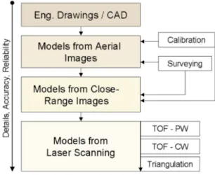
Digitally reconstructing a large and complex heritage site, for example a medieval castle, for documentation and virtual reality simulation is a challenging task that requires combining models created by different data sets from several digitisation technologies. Our approach resembles the level of detail (LOD) concept used in visualization of complex models. Our procedure is hierarchical by the data source, whether it is laser scanner, digital images, surveying, or engineering drawings. In the hierarchy, the details, accuracy and reliability increase as we advance from one data level to the next. We will describe our procedure and present its application to three significantly different heritage projects each illustrates a different strategy for data integration.
1. INTRODUCTION
1.1 3D Modelling Techniques
The classic approach to create a 3D model is to build it from scratch using CAD software, surveying data, and engineering drawings. This is obviously time consuming, impractical, and costly for complex heritage sites. The created models are not photo-realistic and do not include all the fine details. Standard Photogrammetry, although can produce accurate and photo-realistic models, remains highly interactive. Currently more efforts are directed to increasing automation and realism by advanced image-based techniques or directly digitising the object with a laser scanner. However, accurately capturing all details fully automatically for all types of objects and scenes remains elusive. For small and medium size objects, laser scanners can provide accurate and complete details with high degree of automation. But they can be bulky, costly, affected by surface reflective properties, and not easy to operate. Also a laser scanner is intended for a specific range, thus one designed for close range may not be suitable for medium or long range. Image based approaches entail widely available hardware and potentially the same system can be used for a wide range of objects and scenes and are capable of producing geometrically accurate and realistic looking models. The problems include capturing details on unmarked and sculpted surfaces and full automation. Although there is no clear definition, a complex site may consist of multiple structures of different types and may require a large number of images or scans to completely reconstruct in 3D. Some successful application specific examples do exist, such as urban or city models. The success of those systems increases with the use of multiple sensors and the availability of CAD models describing all possible house or roof shapes. The research presented in this paper is an attempt to develop some of the tools needed for a flexible approach to
model any complex heritage site. Our procedure is hierarchical by the data source (figure 1). In the hierarchy, the details, accuracy and reliability increase as we advance from one data level to the next. As a rule, data in one level overrides data in previous levels. In this paper we present examples from existing and destroyed or partially destroyed heritage sites.
Figure 1. Hierarchy of model assembly 1.2 Combining Engineering Drawings and Sensor Data Use of existing engineering drawings with digitally acquired sensor-based 3D data may be divided into three categories: 1. The drawings are the prime source while sensor-based
technique are used for only some parts, mainly those missing from drawings, for example because they are too small for the scale factor used, or adds detail for complex parts that can not be modelled from the drawings. Images may also be used * Corresponding author.
as texture on geometry fully created from drawings. We present the Rideau Chapel project as example (section 5.1). 2. Parts are entirely modelled from drawings and different parts
are entirely modelled from sensor data. Separately modelled parts are then connected together using joint portals. We present Temple C of Selinunte, Sicily, as example (section 5.2). 3. Sensor-based data is the prime source while the drawings are
used to cover the missing parts. The drawings here are also used to assemble the sensor-based models. The Stenico castle in Trentino, Italy is presented as example (section 5.3).
The first category is traditionally the one used for most projects in the past because sensor-based techniques were not advanced enough to do a complex site. The third category is the most desired because it gives the truly "as built" representation, or the most faithful documentation, and can give a photo-realistic look rather than a computer-generated look. The second category can be useful if there are entire sections that are poorly accessible for sensor acquisition, or there are entire sections that are straightforward to model from floor plan, for example simple rooms which have nothing of interest. Each of the above three categories may have different assembly procedure.
2. PREVIOUS WORK 2.1 2.2 2.3 2.4 2.5 3.1 3.2 CAD with Architectural Drawings / Floor Plans
Traditional 3-D CAD techniques using architectural drawings remain the most common [Haval, 2000]. Many use synthetic textures, which yield a computer-generated look, but some use textures from photos, which offer more realistic appearance [Foni et al, 2002]. The approaches typically lack automation, although Dikaiakou et al, 2003, modelled heritage buildings in Nicosia using an automated CAD building generation technique based on a library of predefined 3D building blocks.
Surveying and Interactive Photogrammetry
Over the past few decades, surveying and photogrammetry have been applied to heritage sites documentation. For example, Hanke et al, 2002, modelled the medieval fortress Kufstein, Austria, using images taken from a helicopter a by metric film camera, ground images by non-metric camera, and surveying. CAD software was used to fill in missing parts. Bacigalupo and Cessari, 2003, used Photogrammetry and surveying to model medieval castles in Western Sicily. The methods are still labour intensive and projects may take years to complete.
Automated Image-Based Modelling
To our knowledge, no large complex-site was modelled based purely on fully automated image-based techniques, but parts of sites have been modelled automatically [Pollefeys et al, 1999]. Closely spaced images, like low-resolution videos, are needed. This may be difficult to acquire for a full site. Even if access is not an issue, covering a large site with closely spaced image sequences is time consuming. Also, accuracy becomes an issue on long sequences due to error propagation. However, the technique can be useful on parts of the site with well-defined features. Most of the efforts are focused on the automatic recovery of internal and external camera parameters and stereo matching of extracted points. On the other hand, acquiring points suitable for modelling and creating the model itself, which involves segmenting point clouds into topologically meaningful groups, remain interactive procedures. Many
techniques attempt the full automation of the modelling process [Werner and Zisserman, 2002] or improving the accuracy of the final model [Cantzler, 2003]. The techniques rely on constraints of surface shapes and assumed relationships between surfaces.
Laser Scanning
Laser scanners have been used to acquire the entire geometry in some large-scale projects [e.g. Allen et al, 2003]. The scanners promise to provide highly detailed and accurate representation of any shape. Combined with colour information, either from the scanner itself or from a digital camera, a realistic-looking model can be created. The accuracy at a given range varies significantly from one type of scanner to another [Blais, 2004]. Also, due to object size, shape, and occlusions, it is usually necessary to use multiple scans from different locations to cover every surface. Aligning and integrating the different scans will affect the final accuracy of the 3-D model.
Combination of Multiple Techniques
Flack et al, 2001, developed tools specifically designed to assemble models created by various techniques. Georgopoulos and Modatsos, 2002, utilized available tourist slides and existing engineering drawings and geodetic measurements to model the church of Holy Sepulchre in Jerusalem. Bundle adjustment with self-calibration on the digitised slides, with geodetic and engineering drawings measurements as control, was used in that 7-years-long project. Beraldin et al, 2005, combined laser scanning, photogrammetry, and CAD to model two heritage sites. El-Hakim et al, 2003, used aerial and terrestrial images for the main shapes, and laser scanning for fine details to fully model the abbey of Pomposa in Italy.
3. 3D MODELING: ISSUES AND ANALYSIS Data Acquisition
More often than not, heritage-sites settings make it difficult to find sufficient suitable locations to take images or scans. Also the size and complexity of the structures may require a huge amount of data to cover all the details. Low-flying helicopter may be the solution to cover outer walls, roofs, and courtyards with a practical number of images. Ground images or scans at selected locations can furnish the details of some of the areas.
Modelling from Floor Plans
After acquiring all possible sensor data, we may still have some sections without coverage. These parts can be determined from existing architectural drawings or floor plans. Drawings can also be used to model simple and uninteresting parts. In the case of drawings created directly in digital form from surveying data, file formats such as DXF allow the information to be arranged in separate layers. Adjustments to obtain consistent local geometry and layout topology are needed. Creating 3-D models may be done interactively on simple plans, but can be time consuming on complex buildings. Thus, semi-automatic techniques were developed to create 3-D models from such plans [Lewis and Sequin, 1998]. Commercial CAD software does not address the situation where a drawing only exists in analogue form. Therefore, significant research has been devoted to convert such drawings to CAD representation. This can be difficult due to the complexity and variety of drawing notations and the necessity to handle noise and unwanted features.
Kernighan et al, 1996, developed a technique that can extract lines and poly-lines from digitised floor plans and remove any information not needed for 3-D modelling.
3.3 3.4 4.1 4.2 4.3 4.4 4.5 Limited Geometric Constraints
Many of the automated modelling techniques mentioned in 2.3 rely on assumptions made about surface shapes and relations between surfaces such as plane perpendicularity and parallelism and the availability of vanishing points from multiple sets of parallel lines. However, these assumptions do not apply to most classical heritage structures. This limits the applicability of many automated techniques therefore we have to acquire the 3-D coordinates without assumptions. The exceptions may be arches, columns, or windows whose shapes are mostly regular and can be modelled semi-automatically [El-Hakim, 2002].
Model Assembly and Integration
Models created from different sets of data must be assembled to create one model suitable for documentation and visualization. In addition to differences in coordinate systems and scale, the models will also not perfectly match at joint primitives such as surfaces, edges, and vertices. Some of those will overlap or intersect and some will be disjointed, which is unacceptable. Again, commercial CAD and rendering software do not address these problems therefore a procedure must be developed to seamlessly put together different models.
4. DETAILS OF THE APPROACH
Our approach resembles the level of detail (LOD) concept used in visualization of complex models. Some city modelling techniques also use an adaptation of this idea [Lee and Nevatia, 2003]. Our procedure is hierarchical by the data source (figure 1). In the hierarchy, the details, accuracy and reliability increase as we advance from one data level to the next. As a rule, data in one level overrides and replaces the overlapped data found in previous levels. The approach can be summarized as follows: 1. Calibrate the digital camera for its internal parameters. 2. Acquire a floor plan in digital form and create rough model. 3. If possible, survey some points with total station.
4. Acquire aerial images and create the overall model. 5. Create detailed models from terrestrial images. 6. When available, a high-accuracy laser scanner.
7. Register and integrate the models created from sensor data. 8. Parts without data exposure are completed from floor plans. We detail some of the steps in the following sub-sections.
Camera Calibration
Self-calibration is necessary if camera settings are unknown and vary between images. But to achieve accurate self-calibration, certain geometric configurations of images are needed. Since this is not guaranteed at the project site, it is sensible to use high-quality camera and take the images at fixed known settings and calibrate at those settings using surveyed points. Many modern digital cameras can save a number of settings.
Three-Dimensional Information from Floor Plans 3-D information from floor plans has two main purposes: to add sections missed by imaging or scanning, and to support the
modelling process by verifying surface shapes and the relationships between surfaces. To convert the floor plans into a 3-D model we need to provide semantic information such as room identities and connecting openings followed by walls extrusion to given heights. The heights will be known from the sensor-based models. Window and door insertions are carried out where needed.
The Overall Model from Aerial Images
Traditionally aerial images are used to model terrain and roof tops. Here we suggest, whenever possible, images from a low flying helicopter at various viewing angles around the site to model roofs, outside of buildings, courtyards, surroundings and close-by grounds. The images will likely have strong geometric configurations - being convergent with large base-to-height ratio. Bundle adjustment is applied to measured image points.
Detailed Models from Ground Images
Images from ground levels are used to semi-automatically create detailed models of selected elements such as entrances, sections occluded from the aerial views, and indoor spaces. We start by manually creating a less-detailed model with selected seed points using bundle adjustment. Corners are automatically extracted followed by stereo matching procedure [El-Hakim, 1989], constrained by the epipolar line and disparity-range determined automatically from the seed points. Finally, 3-D points on regular shapes like columns, arches, doors, and windows are created semi-automatically using selected seed points, as described in El-Hakim, 2002. This is implemented in
ShapeCapture® software [http://www.shapecapture.com]. Detailed Models from Laser Scanning
One of the most important issues is to determine the spatial resolution to be used. This depends on the desired level of details, the type of scanner, and the size of the site. The number of scans is affected by the spatial resolution and the surface shape complexity, such as occlusions and hard to reach areas. We use PolyWorks software tools from Innovmetric Inc. for multi scan registration and for creating the triangular mesh. 4.6 Model Assembly
Combining models created by different data sets (figure 2), must address three main issues, which are usually not handled by commercial modeling software. Thus we created tools to: • Correctly determined relative scale and orientation.
• Perfectly match joint primitives, such as edges, and vertices, from adjacent models. This is complex because it is unlikely that we have the same primitives between adjacent models. • Remove gaps, redundant or intersecting edges.
Determining the scale and orientation (registration) will be unnecessary if the individual models were directly created in the same coordinate system using control points. Many models however will not have control points and will need interactive registration. The models are organized in a hierarchical manner where the top model contains the least details (according to figure 1). We import points from the detailed model along the perimeter of common surfaces into the less-detailed model. Then we adjust the latter’s mesh with the new added points to create a hole into which we insert the detailed model.
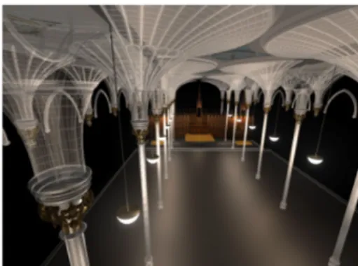
Figure 6: Chapel exterior model from old images. The chapel measured 32 m x 14.5 m x 8.5 m (H). We needed several techniques: CAD modelling from existing engineering drawings, Photogrammetry, laser scanning from a long range and high precision close range scanner, and modelling from old photographs. The existing engineering drawings, which were based on surveying, and Photogrammetry created the overall model of the interior of the chapel (figure 3). More details on the walls and ceiling were obtained by a time-of-flight scanner with 5 mm resolution (figure 4), while fine details on sculpted surfaces were obtained by a close-range triangulation-based scanner with 0.5 mm resolution (figure 5). The outside of the chapel was modelled from old photographs taken in the early 1970’s (see the model in figure 6). All models were assembled with the technique described in section 4.6.
5. APPLICATIONS
5.1 Chapel of Convent of Our Lady of the Sacred Heart (the Rideau Chapel), Ottawa, Canada
The chapel, one of the most beautiful and architecturally unique chapels in Canada, was built in 1887 but unfortunately was destroyed in 1972. However, before its destruction, the interior was dismantled and later assembled and installed inside the National Gallery of Canada in Ottawa. This project objective is to model the existing interior from the reassembled site and the destroyed exterior from existing records and images, and create a complete virtual reconstruction of the chapel as it once was.
5.2 Temple “C” of Selinunte, Sicily
Selinunte, Sicily is the site of some historically important Greek ruins such as the 6th century, BC, Temple “C”, or Apollo’s temple (figure 7a). This is an example of a site that needed a mixture of technologies to digitally reconstruct it. The 3D modeling was performed using two different types of laser scanner, Photogrammetry and CAD tools. The room, at the Archeology museum in Palermo, containing artifacts from the site in Selinunte (figure 7b) was completely modeled with the combined technologies.
Figure 3: Model by engineering drawings and Photogrammetry
(a) (b)
Figure 7: (a) Temple C as it stands now, (b) room dedicated to Selinunte at the Archeology museum in Palermo The project is divided into two broad steps, the first step saw the modelling of the frieze of temple C, located at the museum, using 3D laser scanning and the second step will see the reconstruction of temple C of the Acropolis of Selinunte using CAD tools. The CAD model will be based on historical information available at the University of Lecce and at the “Museo Archeologico Regionale” of Palermo, Sicily. Figure 8 shows the results of the modelling of a Metope known as “Perseo and Medusa”. Laser scanning and texture mapping were used to create this model. The same technique was applied on the other two Metopes associated to temple C. The average size of the three Metopes is 1m × 1m × 0.4m. We continued the laser scanning work using two types of laser scanners on different sections inside the museum room. The first scanner was used to acquire details in the order of 0.5 mm and the second scanner captured details in the range of 2-10 mm. The Figure 4: Model from TOF laser scanner
rest of the 3D model of the room was created using photogrammetry-based modelling techniques (figures 9 and 10) and CAD modelling. A rendering of the complete museum room is shown in Figure 11.
Figure 8: Detailed model from laser scanner
Figure 9: Two views of the Photogrammetry model
Figure 10: Textured mapped Photogrammetry model
Figure 11: Model from scanning, Photogrammetry, and CAD. 5.3 The Stenico Castle, Trentino, Italy
The castle is one of the oldest and most important medieval castles in the region, and is an interesting mixture of styles of buildings added over several centuries. The procedure described in section 4 is applied to modelling the castle, which consists of
several components (figure 12), mainly: buildings of mixed styles organized around 4 courtyards, tall thick walls with arched gates, a Renaissance loggia, several towers, and the 13th century San Martino’s chapel with medieval frescos.
Figure 12: Two views of the Stenico castle.
We used a 5-mega-pixels Olympus® E-20 digital camera to take
several sets of aerial (from helicopter) and ground images. The imaging took a total of 4 hours in two visits to the site. Two camera settings were used during the project, one at the shortest and one at the longest focal length depending on the available space around the object. Data acquisition costs include the digital camera, the rent of the helicopter for one hour, and surveying of 115 points (one day) with a Leica® total station.
ShapeCapture® software has been used for calibration, bundle adjustment, and image-based modelling. A general model was created from the aerial images, and 17 detailed models were created using sets of ground images, including models of the St. Martin’s chapel, the towers, the loggia, the entrances, and details of the walls enclosing the courtyards. Figures 13-15 show snapshots of some models. The procedure, which needs 10-20% of the points to be measured interactively, required an average of 1-2 days of work by one person for each model.
Figure 13: General model of castle buildings.
Figure 14: Detailed model of the loggia.
The castle structures extend over an area of about 100 meters by 64 meters and have up to 35 meters height. The castle grounds are elevated by over 30 meters above the road approaching it. The aerial images were taken from an average range of 120 meters and average vertical distance of 65 meters above the castle. The field of view of each image usually
covered all buildings, with an average view width of about 160 meters. One pixel in the image corresponds to about 8 cm. The accuracy is assessed by the variance-covariance matrix of the least-squares-computed 3-D points, and validated by surveyed checkpoints that had 3 mm accuracy. The achieved accuracy was in fact homogeneous in the three coordinates and averaged: 17mm (X), 15mm (Y), and 16mm (Z). This is one part in 10,000 and represents 0.2 pixels. For the ground-level models, we achieved accuracies of: 1mm to 2mm, which give average relative accuracy of one part in 6,000 and represents 0.3 pixels. The superior relative accuracy reached from aerial images, even though they were taken from much longer ranges, is attributed to the better geometric configuration compared to ground images. Ground images had less than ideal locations due to obstructions and tight spaces around most buildings.
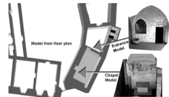
Applying the model assembly procedure presented in section 4.6, we started by superimposing the general model on the floor plan. Using the floor plan as a guide, detailed models such as the loggia in figure 14, and indoor models such as the chapel, were then inserted. Detailed models of gates, windows, and other details are connected to the general model using points along common regions. The general model was then re-triangulated to account for point changes and to create a hole where detailed models are inserted. Finally, sections still missing from the general model were added from the floor plan using known wall heights.
6. CONCLUDING REMARKS
We have reached solid conclusions about the effectiveness of combined techniques for complex site modeling. Using laser scanning and digital images, combined with existing floor plans and limited surveying, we can completely model a complex site with realistic details. Our procedure is hierarchical by the data source, whether it is laser scanner, digital images, surveying, or engineering drawings. In the hierarchy, the details, accuracy and reliability increase as we advance from one data level to the next. Semi-automated modeling and model assembly techniques and tools were developed and tested on three significantly different heritage sites. The results were highly accurate, fully detailed, and photo-realistic. The cost and time required was much less than reported similar work.
Acknowledgements
The virtual re-building of temple C of Selinunte is part of Activity 4 of the project LandLab, co-financed by the EU. We also thank Dr. Franco Marzatico, the director of Castelli Trentini, and the Autonomous Province of Trento for allowing us access to the Stenico castle. Charles Hill of the National Gallery of Canada provided us with unlimited access to the Rideau chapel set up at the gallery.
References
Allen, P.K., et al, 2003. New methods for digital modeling of historic sites. IEEE Computer Graphics and Applications, 23(6), Nov./Dec., pp. 32-41.
Bacigalupo, C., Cessari, L., 2003. Survey techniques and virtual reality for recovery plan of a fortified Mediterranean town, Int. Workshop Vision Techniques for Digital Architectural and Archaeological Archives, Ancona, July, pp. 40-42.
Beraldin, J.-A., et al, 2005. Combining 3D technologies for cultural heritage interpretation and entertainment, SPIE Proc. Vol. 5665, Videometrics VIII, San Jose, CA., pp. 108-118. Blais, F., 2004. Review of 20 years of range sensor development, J. Electronic Imaging, 13(1), Jan., pp. 232-240. Cantzler, H., 2003, Improving architectural 3D reconstruction by constrained modeling. Ph.D. Thesis, School of Informatics, University of Edinburgh, Scotland.
Dikaiakou, M., Efthymiou, A., Chrysanthou, Y., 2003. Modeling the walled city of Nicosia, 4th International Symposium on Virtual Reality, Archaeology and Intelligent Cultural Heritage (VAST’2003), pp. 57-66.
El-Hakim, S.F., 1989. A hierarchical approach to stereo vision,
P. E. & R. S., 55(4), April, pp. 443-448.
El-Hakim, S.F., 2002. Semi-automatic 3d reconstruction of occluded and unmarked surfaces from widely separated views, Proc. ISPRS Symp., Corfu, Greece, Sept, pp. 143-148.
El-Hakim, S.F., Beraldin, J.-A., Picard, M., Vettore, A., 2003. Effective 3D modeling of heritage sites, 4th Int. Conf. 3D Imaging and Modeling (3DIM'03), Banff, Canada, pp. 302-309. Flack, P., et al, 2001. Scene assembly for large scale urban reconstructions, Proc. VAST 2001, pp. 227-234.
Foni, A.E., Papagiannakis, G., Magnenat-Thalmann, N. 2002. Virtual Hagia Sophia: restitution, virtualization and virtual life simulation. UNESCO World Heritage Congress, Oct.
Georgopoulos, A., Modatsos, M., 2002. Non-metric bird’s eye view, Proc. ISPRS Comm. V Symp., Corfu, pp. 359-362.
Hanke, K., Oberschneider, M., 2002. The medieval fortress Kufstein, Austria – an example for the restitution and visualization of cultural heritage, Proc. ISPRS Comm. V Symp., Corfu, Greece, Sept., pp. 530-533.
Haval, N., 2000. Three-dimensional documentation of complex heritage structures, IEEE Multimedia, 7 (2), Apr-Jun, pp. 52-56. Kernighan, B.W., Van Wyk, C.J., 1996. Extracting geometric information from architectural drawings. Proc. Workshop on Applied Computational Geometry (WACG), May, pp. 82-87. Lee, S.C., Nevatia, R., 2003. Interactive 3D building modelling using a hierarchical representation, IEEE Workshop Higher-Level Knowledge in 3D Modelling and Motion Analysis (HLK’03), with ICCV’03, Nice, October, pp. 58-65.
Lewis, R., Sequin, C., 1998. Generation of 3D building models from 2D architectural plans, Computer-Aided Design, 30(10), Sept., pp. 765-779.
Pollefeys, M., et al, 1999. Hand-held acquisition of 3D models with a video camera, 2nd Int. Conf. 3-D Digital Imaging and Modeling (3DIM’99), Ottawa, Oct., pp. 14- 23.
Werner, T., Zisserman, A., 2002. New technique for automated architectural reconstruction from photographs, Proc. 7th Europe. Conf. Computer Vision, vol. 2, pp. 541-555.