HAL Id: hal-00830446
https://hal.archives-ouvertes.fr/hal-00830446
Submitted on 5 Jun 2013
HAL is a multi-disciplinary open access
archive for the deposit and dissemination of
sci-entific research documents, whether they are
pub-lished or not. The documents may come from
teaching and research institutions in France or
abroad, or from public or private research centers.
L’archive ouverte pluridisciplinaire HAL, est
destinée au dépôt et à la diffusion de documents
scientifiques de niveau recherche, publiés ou non,
émanant des établissements d’enseignement et de
recherche français ou étrangers, des laboratoires
publics ou privés.
Usman Zabit, Olivier Bernal, Thierry Bosch
To cite this version:
Usman Zabit, Olivier Bernal, Thierry Bosch. Design and analysis of an embedded accelerometer
coupled Self-Mixing laser displacement sensor. IEEE Sensors Journal, Institute of Electrical and
Electronics Engineers, 2013, 13 (6), pp.2200-2207. �10.1109/JSEN.2013.2251626�. �hal-00830446�
redistribution to servers or lists, or reuse of any copyrighted components of this work in other works.
Abstract—The paper presents the operating principle and signal processing needed for the design of a reliable solid-state accelerometer (SSA) coupled self-mixing (SM) interferometric laser displacement sensor for embedded applications. The influence of signal processing methods and accelerometer characteristics on the complete sensing system performance is studied. Then, four different SSA-SM sensing systems are examined and characterized. By comparing their performance, it is thus seen that the sensing system precision is limited by the noise density of the employed accelerometer as well as the used SM displacement retrieval technique whereas the system bandwidth is mainly limited by the choice of a given accelerometer. Furthermore, this paper analyzes the phase and gain matching properties that the SSA-SM should reach in order to guarantee proper extraneous vibrations correction. Finally, the proof of concept of a real-time SSA-SM sensing system indicating 30 dB correction is presented. This prototype thus demonstrates the possibility of using such a real-time sensing system for those embedded and industrial applications where the presence of extraneous movements would hinder traditional sensors use.
Index Terms—embedded sensing, displacement measurement, self-mixing interferometry, accelerometer
I. INTRODUCTION
elf-mixing (SM) or optical feedback interferometry [1-3] is being actively employed for displacement sensing [4-7]. However, its use for embedded applications is a major challenge. It is so as these sensors have traditionally needed a stationary support (such as an optical table and/or anti-vibration material) to guarantee an accurate target measurement. Otherwise, any movement of the sensor can corrupt the true target displacement measurement. Such a situation has thus restricted the use of SM sensors for embedded applications.
A correction of the falsified measurement due to a non-stationary laser sensor is not as straight forward as it may appear. In this regard, an interesting solution has been proposed by the differential SM vibrometer [8] which measures differential vibrations between two targets while using electronic channel subtraction. Such a technique is based on a reference laser pointing on a stationary target surface [8].
Now, in spite of the elegance of this technique, it cannot be used to measure the displacement of one single target while removing the influence of external disturbances if an absolutely stationary reference target is not at hand. Such a constraint, however, is part of the nature of embedded sensing. On the other hand, the use of a Solid-State Accelerometer (SSA) can be the answer for embedded sensing as it allows the retrieval of displacement relative to a standstill position thereby enabling the use of SM sensors for embedded applications. A basic offline SSA coupled Self-Mixing (SSA-SM) sensing system has thus been recently proposed [9], though with a final precision poorer than that normally
associated with SM sensors. Nonetheless, it demonstrated that true target displacement can be recovered by using post processing even if the laser sensor is itself in motion.
The aim of the present paper is to analyze and characterize in detail such a SSA-SM sensing system. In this regard, the influence of hardware (such as employed SSA and laser diode wavelength λ) and processing (such as displacement extraction algorithms) on final precision has been tabulated. As the SSA is the heart of our embedded sensing system, so four different offline SSA-SM sensing systems have been designed and tested under equivalent conditions. The ensuing comparison provides valuable information useful for the design of a custom SSA-SM sensing system of desired measurement precision, range, and bandwidth. It also confirms the SSA noise contribution to the final precision of the proposed sensing system. Finally, a real-time SSA-SM sensing system proto-type is presented that demonstrates the feasibility and validity of a real-time SSA-SM sensing system.
II. SSA-SMSENSING SYSTEM
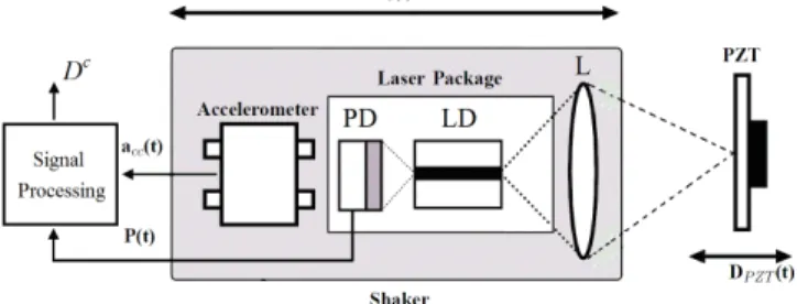
Fig. 1 presents a schematic diagram of a SSA-SM sensing system. The solid-state MEMS (micro-electro-mechanical system) accelerometer measures the laser sensor head displacement (noted as Ds) and a subsequent subtraction of
this displacement from the global (falsified) SM displacement provides the corrected displacement (noted as Dc) reflective of the true target displacement (noted as DPZT).
Design and analysis of an embedded
accelerometer coupled Self-Mixing laser
displacement sensor
U. Zabit, Member, IEEE O.D. Bernal, Member, IEEE and T. Bosch, Senior Member, IEEE
Fig.1. Schematic block diagram of the Solid-State Accelerometer coupled Self-Mixing (SSA-SM) sensing system: photodiode (PD), laser diode (LD), lens (L), and piezoelectric transducer (PZT).
Let us now start with a presentation of the signal processing used for the SSA-SM sensing system. Fig. 2 details its three main processing units, each of which is explained below.
A. Self-Mixing Signal
SM effect occurs in a laser when a part of the beam backscattered by a target is coupled back into the laser cavity and causes interference with the emitted beam, thus modifying the spectral properties of the laser. The variations in the optical output power of the laser diode P(t) caused by this optical feedback are then used to retrieve the target displacement D(t). Traditionally, P(t) is read by the built-in photodiode (PD) contained in the laser diode (LD) package.
For the first part of this paper dedicated to performance analysis of different SSA-SM sensing systems, offline post-processing for SM displacement retrieval was done by using the Phase Unwrapping Method (PUM) offering a precision of
λ/16 [10], as also seen from the experimental result of Fig. 3. In this paper, this displacement retrieved from the SM signal P(t) has been denoted as DΣ since it is the sum of the true target displacement DPZT and the displacement undergone
by the sensor Ds.
Fig. 2. Block diagram of the signal processing used by Solid-State Accelerometer coupled Self-Mixing (SSA-SM) sensing system.
B. Acceleration Signal
The displacement undergone by the sensor itself and measured through the acceleration signal (Ds) is obtained by
using the SSA. In order to do so, the acceleration signal acc(t)
is filtered and integrated twice, as indicated in the lower half of Fig. 2. The band-pass filtering is done over the operating bandwidth of 20Hz-500Hz so that low-frequency drifts that can falsify the subsequent integration steps as well as high frequency acceleration signal saturation can be effectively
given low cutoff frequency is closely related to the overall SSA-SM sensing system measurement precision. For the first part of this paper dedicated to the performance analysis of a given SSA-SM sensing system, offline post-processing of acc(t) was done on a computer by using Riemann sums
algorithm and ideal band-pass filters for integration and filtering respectively.
Fig. 3. (a) Target movement at 79Hz, (b) corresponding SM signal for a LD emitting at 785nm, (c) PUM based displacement retrieval, and (d) difference between signals in (a) and (c) shown in blue is less than 50 nm and root mean square (RMS) error shown in dotted red is 21 nm.
C. Phase and Gain Matching
In order to properly merge DΣ and Ds (see Fig. 2), phase (φ)
and gain (G) calibrations need to be done. This is necessary as both signals i.e. the self-mixing signal and the acceleration signal pass through their respective signal amplification, acquisition, and processing stages all of which may introduce phase and gain errors in both signals. The influence of these phase and gain errors on overall system precision will be detailed in section IV.3.
Finally, the signal matching of the two signals (DΣ and Ds)
is followed by the last step of their subtraction (see Fig. 2) that allows us to obtain the corrected displacement Dc.
III. EXPERIMENTAL SET-UP
In order to analyze the influence of a given SSA on the overall SSA-SM sensing system, four different SSAs
(ADXL311 accelerometer from Analog-Devices1,
LIS344ALH accelerometer from ST1, MS9000 and SF1500 from Colibrys1) were used. The key characteristics of these four SSAs are summarized in Table I. The noise density values reported in the Table I are typical values provided in component datasheets. These were then used to calculate the corresponding theoretical displacement precision values for 20Hz-500Hz bandwidth.
The first three accelerometers were fixed on the SM sensor laser head so that these could simultaneously measure as faithfully as possible the movement undergone by the SM
redistribution to servers or lists, or reuse of any copyrighted components of this work in other works. sensor (see Fig. 4). The employed SM sensor was based on a
Sanyo DL7140 laser diode emitting at λ=785 nm with an output power of 60mW. The set-up seen in Fig. 4 thus allowed us to simultaneously acquire data for subsequent post- processing for these three SSA-SM sensing systems.
TABLE I
CHARACTERISTICS OF FOUR DIFFERENT ACCELEROMETERS USED
Fig. 4. Coupling of three different MEMS accelerometers (ADXL311, LIS344ALH, and MS9000) with a SM displacement sensor based on DL7140 laser diode. The sensor head has been mounted on a mechanical shaker.
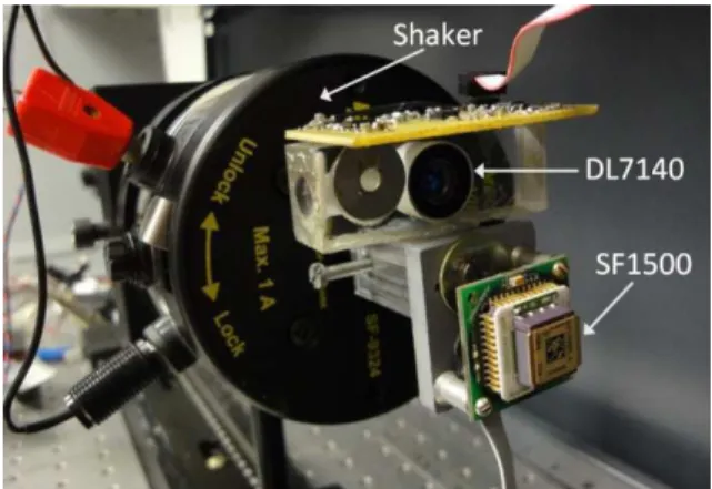
Fig. 5. Coupling of SF1500 accelerometer with the Self-Mixing displacement sensor based on DL7140 laser diode. The sensor head has been mounted on a mechanical shaker.
In a similar manner, the fourth SSA (SF1500 used here in a single-ended output configuration) was also coupled with another SM sensor based on the same DL7140 laser diode (see Fig. 5). Care was then taken to test this fourth SSA-SM sensing system under equivalent conditions as would be later attested during the performance comparison of these four SSA-SM systems.
The SSA-SM sensing system was then mounted on a mechanical shaker (Fig. 4 and Fig. 5). The shaker was used to generate the displacement Ds undergone by the SSA-SM
sensing system (see Fig. 1). Then, an initial phase and gain
calibration between the accelerometers and SM sensor was performed so that these would provide the same response for a given excitation. This was achieved by exciting the shaker with a step of 20Hz over the operating bandwidth of 20Hz-500Hz for a stationary target. The obtained phase and gain coefficients were stored in a look-up table so that these could be used for subsequent offline phase and gain matching.
After the calibration phase, the SSA-SM sensing system was ready for target measurements. For this purpose, a piezoelectric transducer (PZT) actuator from Physik Instrumente (P753.2CD) was used as target (see Fig. 1). It has a built-in capacitive feedback sensor with 2 nm precision that was used as a reference sensor for the PZT movement (DPZT).
IV. EVALUATION OF FOUR SSA-SM SYSTEMS
Before presenting the experimental results used for the performance comparison of our four different SSA-SM systems undergoing extraneous vibrations, let us look into the sources that have an effect on the final precision of a given SSA-SM sensing system.
A. Estimation of SSA-SM System Precision
As already detailed in the previous section, there are three main processing blocks for a SSA-SM system all of which may introduce error thus reducing the final precision of the SSA-SM system. These three are discussed below.
1) Self-Mixing Displacement Retrieval Method
The method used to retrieve displacement information from a given SM signal would contribute an error to the final SSA-SM system precision. The use of PUM for retrieving displacement from a SM sensor signal based on a 785nm wavelength LD thus introduces an RMS error of approximately 20nm.
2) Accelerometer Noise Resolution
The noise density of a given SSA, expressed as µg/1Hz, has a direct impact on the displacement measurement resolution for a given low cutoff frequency of its bandwidth [11]. As displacement extraction from acceleration signal involves double integration, so the noise power spectrum density of the displacement SD can be given in the frequency domain as [9]
4
)
(
)
(
s
s
S
s
S
acc D=
(1)Consequently, the displacement resolution of the SSA signal depends on the low cutoff frequency of the system. Fig. 6 presents the displacement resolution as a function of noise density of four different SSAs for varying lower cutoff frequency values of the operating bandwidth. For the measured noise density of 161µg/1Hz, 22µg/1Hz, 17µg/1Hz, and 4.5µg/1Hz for ADXL, LIS344ALH, MS9000, and SF1500 respectively, theoretical displacement precision of approximately 251nm, 35nm, 27nm, and 4.5nm respectively is to be expected for a 20Hz lower cutoff.
Fig. 6. The displacement resolution as a function of measured noise density of our four accelerometers for different lower cutoff frequency values of operating bandwidth.
3) Gain and Phase Mismatch
As the elimination of an extraneous movement acting on SSA-SM system supposes an exact phase and gain matching between the SSA and SM processing chains (see Fig. 2), so it is easy to see that any mismatch of phase and gain coefficients would result in a residual error after the subtraction DΣ - Ds.
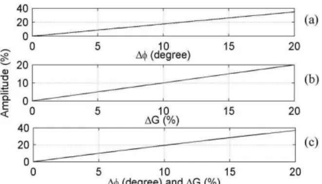
Such a residual signal would then directly contribute in reducing the final SSA-SM sensing system precision. Denoting gain mismatch as ∆G and phase mismatch as ∆φ, Fig. 7 presents the amplitude of such a residue as a percent of the extraneous motion acting on the SSA-SM system. Assuming a sinusoidal extraneous motion with 2µm amplitude, it can then be calculated that a residual signal of 5.3nm amplitude would appear in the final output of SSA-SM system for ∆G=0.2% and ∆φ=0.1 degrees.
Fig. 7. Influence of a mismatch in Gain and Phase coefficients on the elimination of extraneous movement acting on SSA-SM sensing system. (a) Percent amplitude of [sin(ωt)-sin(ωt-∆φ)], (b) percent amplitude of [sin(ωt)- (1-∆G)sin(ωt)], and (c) percent amplitude of [sin(ωt)-(1-∆G)sin (ωt-∆φ)].
So, it can be said that the imprecision ξc in the final SSA-SM system output Dc would have uncorrelated contributions from the above-mentioned three errors and can be expressed as 2 2 2 ∆
+
+
≈
ξ
ξ
ξ
ξ
SM acc c (2)where ξSM is the error in SM displacement extraction, ξacc is the error brought by a given accelerometer, and ξ∆ is the gain
be affected by stray mechanical, data acquisition, and electronic noise though these effects have not been quantified in the present study.
Now, before detailing the performance of a valid correction of the extraneous movements acting on the SSA-SM system by the use of the previously outlined signal processing steps, let us observe the frequency spectra of the displacement signals (DΣ and Ds).
B. Frequency Spectra Analysis
Fig. 8 shows these frequency spectra of displacements calculated from the acceleration signals of four accelerometers (ADXL311, LIS344ALH, MS9000, and SF1500) and from the displacement retrieved from the Self-Mixing (SM) signal. The signals were obtained for a stationary PZT while the shaker vibrated at 90Hz with a 5.2µm peak-to-peak (p-p) amplitude.
Fig. 8. Frequency spectra of displacements from the acceleration signals of four different SSAs as well as the displacement retrieved from the SM signal.
It can be seen in Fig. 8 (a) that the noise present in the 20Hz-500Hz bandwidth for the signal from ADXL311 is the largest while that of SF1500 is the smallest among the four tested SSAs. Such a result is quite evident keeping in mind the SSA characteristics presented in Table I and thus confirms their respective noise resolutions. Likewise, their comparison with that of SM signal also indicates the largest difference among the four SSA signals.
Another interesting comparison is between the frequency spectra of LIS344ALH accelerometer based displacement signal and that of MS9000 accelerometer based displacement signal. It is seen in Fig. 8 (b) that these two spectra present approximately similar noise levels over the 20Hz-500Hz operating bandwidth of our SSA-SM sensing systems. MS9000 though presents relatively smaller noise level. Now, a comparison of these two SSAs with that of SM signal indicates similar noise levels. Hence, it can be expected that each of these two SSAs would result in overall SSA-SM system imprecision of less than 50 nm after all the signal processing needed for extraneous movement correction is
redistribution to servers or lists, or reuse of any copyrighted components of this work in other works. done.
Now, in order to validate the correct working of our SSA-SM systems undergoing extraneous vibrations, the sensor-mounted shaker (acting as a source of extraneous movements acting on the sensor) and the PZT (acting as the target under observation) were both set in motion. The following section presents the results for these test conditions.
Fig. 9. Displacement signals when both shaker and target vibrate at 109Hz.
C. Extraneous Movement Correction
Let us look at the test results for various excitation signals acting on the shaker as well as the PZT. To validate the robustness of our system, the following tests were undertaken: • The shaker as well as the PZT was vibrating at two different frequencies.
• The shaker as well as the PZT was vibrating at the same frequency.
• The shaker vibrated at a single-tone frequency while the PZT was vibrating with an arbitrary signal.
• Two different arbitrary signals were applied to the shaker and to the PZT.
Table II would later present the results for each of the above four types of tests for four different SSA-SM sensing systems. The error values reported in Table II are that of RMS difference between the built-in capacitive feedback sensor of the PZT (used as a reference target sensor DPZT) and the
corrected displacement (Dc) over a bandwidth of 20Hz-500Hz. The arbitrary movements (denoted as ‘arb’ in Table II) are composed of 1st, 2nd, 5th, and 7th harmonic e.g. the signal denoted as ‘arb 51’ is a combination of 51Hz-102Hz-255Hz-357Hz components. The average (denoted as ‘Avg’) and standard deviation (denoted as ‘σ’) are also tabulated.
Let us now look into the case where the shaker as well as the PZT was vibrating at the same frequency. Fig. 9 presents the correction result for the case where the harmonic acting on both the target i.e. the PZT as well as the extraneous vibration acting on the sensor i.e. the shaker is of 109Hz. The corrupted signal i.e. DΣ has an amplitude of 1µm whereas the true target vibration is of 2.5µm. The amplitude of the extraneous vibration Ds acting on the SSA-SM as measured by MS9000
accelerometer is of 3.5µm. By using our technique, a correct signal recovery has been possible as indicated by a favorable comparison between the corrected signal (in red) and the reference signal (in light blue) seen in Fig. 9. The RMS error
is of 51.1nm for MS9000 as reported in Table II. This case is quite important in the sense that it validates the correct working of SSA-SM sensing system for a situation where a mechanical coupling between the target and the sensor assembly can cause the sensor to vibrate at the same frequency thereby resulting in a falsification of measurement.
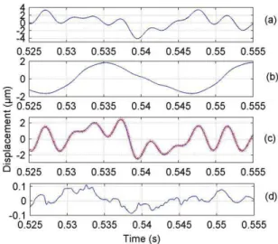
Fig. 10. (a) Corrupted, (b) SF1500, (c) corrected (blue) and reference (dotted red), and (d) 20Hz-500Hz error displacement signals for arbitrarily moving shaker (51Hz-102Hz-255Hz-357Hz) and target (41Hz-82Hz-205Hz-287Hz).
Another case is presented in Fig. 10 where the shaker and the target are both excited by different arbitrarily moving excitation signals. The arbitrary extraneous movement (composed of 51Hz-102Hz-255Hz-357Hz components) picked up by SF1500 accelerometer (Fig. 10 b) and the arbitrary target movement (composed of 41Hz-82Hz-205Hz-287Hz components) picked up by the reference sensor (Fig. 10 c dotted red) attest this case. As a result, the displacement measured by the SM signal is corrupted (Fig. 10 a). However, the SSA-SM sensing system has been able to correctly recover the true target movement as seen in Fig. 10 c (blue curve).
Fig. 11. Frequency spectra of corrupted displacement (a) and corrected displacement (b) signals for arbitrarily moving shaker (51Hz-102Hz-255Hz-357Hz) and target (41Hz-82Hz-205Hz-287Hz). The corrected signal indicates an improvement of 30dB, 47dB, 32dB, and 24dB for 51Hz, 102Hz, 255Hz, and 357Hz respectively (presented by red arrows).
Fig. 11 presents the frequency spectra of the corrupted (DΣ) as well as the corrected (Dc) displacement signals seen in Fig.
improvement of 30dB, 47dB, 32dB, and 24dB for 51Hz, 102Hz, 255Hz, and 357Hz respectively. The final RMS error is of 32.1nm for SF1500 as reported in Table II.
The results summarized in Table II are thus reflective of the performances expected from the used SSAs. It can thus be seen that for the same SM displacement retrieval method (PUM in the present case) and phase and gain matching technique, the final precision of a SSA-SM system is dependent on the noise density of the employed SSA. So, if the objective is to obtain as high a resolution as possible then, logically, the best SSA should be used (SF1500 in our case).
Another way of looking at the results can be based on the choice of SM displacement retrieval method. It can then be observed that for a given low cutoff frequency (20Hz here), the use of a high performance SSA such as SF1500 might not be effective as in such a case, the final precision of a given SSA-SM system is predominantly limited by the precision of the SM retrieval method (20nm for PUM here). So, if the extraneous movements have a relatively higher low cut-off frequency, then the use of an SSA with very low noise density can be considered as overkill.
Keeping in mind the above observations, the choice of LIS344ALH appears judicious for a low-cost SSA-SM sensing system as it offers comparable measurement precision to the SM retrieval method. (Note that the use of an SSA with a relatively higher noise density (such as LIS344ALH) can be tolerated if the extraneous movements have a relatively higher low cut-off frequency (e.g. 20 Hz in the present case). However, the presence of extraneous movements with lower frequencies necessitates a rethink, as detailed below.)
TABLEII
RMSERROR RESULTS (20HZ-500HZ) FOR DIFFERENT MOVEMENTS OF TARGET AND SHAKER AS COMPARED WITH THE PZT REFERENCE SENSOR.
D. Lower Cutoff Frequency
The influence of lowering the SSA-SM cutoff frequency on the final system precision can be seen in Table III where the cut-off frequency has been lowered to 10Hz. A significant increase in ξc is to be expected given the increased contribution of ξacc, as also seen in Fig. 6. Fig. 12 presents the correction using SF1500 for a target vibrating at 99Hz while
This case also highlights the fact that the use of a high performance, low noise density SSA becomes imperative in order to significantly lower the cutoff frequency of SSA-SM sensing system while maintaining a comparable final precision (see the results for SF1500 in Table II and Table III). So, an SSA with very low noise density has to be employed if the extraneous movement has very low frequency components.
TABLEIII
RMSERROR RESULTS (10HZ-500HZ) FOR A SINUSOIDAL MOVEMENT OF TARGET AND SHAKER AS COMPARED WITH THE PZT REFERENCE SENSOR.
Fig. 12. (a) Corrupted (red) and shaker displacement measured by SF1500 (blue), (b) corrected (blue) and reference (dotted red) displacement signals for the shaker vibrating at 11Hz while the target vibrated at 99Hz.
Finally, the proof of concept of a real-time SSA-SM sensing system will be presented below. This prototype has been designed for a 20Hz-500Hz extraneous movement bandwidth by keeping in mind the performances observed during the evaluation of four different offline SSA-SM sensing systems.
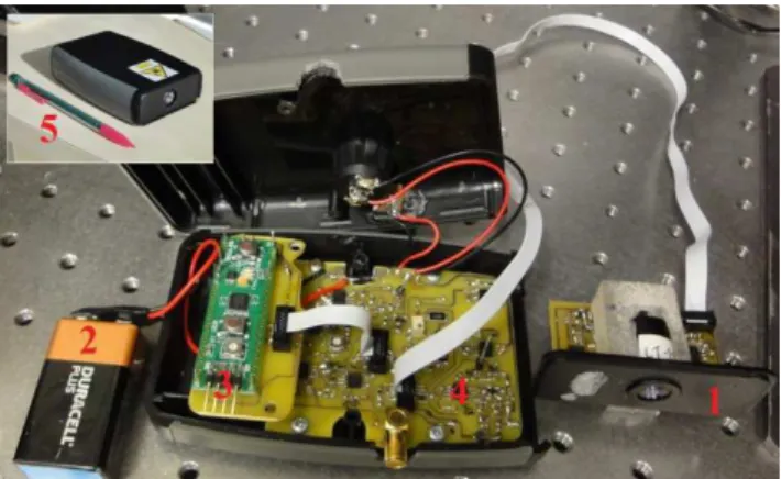
Fig. 13. Real-time SSA-SM sensing system prototype. (1) laser sensor head, (2) battery cell, (3) micro-converter, (4) analog integrators and filters, and (5) Inset picture of prototype.
V. REAL-TIME SSA-SMSENSING SYSTEM
A. Description
redistribution to servers or lists, or reuse of any copyrighted components of this work in other works. LIS344ALH accelerometer and DL7140 laser diode (see Fig.
13). This SSA has been preferred over the other SSAs as it presented the best price to performance ratio over the 20Hz-500Hz bandwidth chosen for the proof of concept. The component cost of the complete prototype is less than 50 $. Note that for a lower cut-off frequency, the same design can be used by choosing an appropriate SSA.
B. Signal Processing
In order to process the SM signal in real-time, a fully analog SM processing technique [12] may have been considered. However, due to the non-harmonic nature of DΣ, we need to use an approach capable of processing such movements while avoiding drift effects. So, for the proof of concept, the SM signal has been processed in real-time using the Consecutive Samples based Unwrapping (CSU) method [13]. It starts by retrieving the SM based displacement through fringe-counting resulting in an initial precision of λ/2. This initial step is quite similar to the initial step of the PUM [10] or the fully analog method [12]. Then, instead of doing an iterative joint-estimation as in PUM, it uses the local SM signal unwrapping as in the fully analog method. Thus, it is able to retrieve SM based displacement with a precision of approximately λ/8.
For the prototype, an integrated micro-converter AduC7020 from Analog Devices® working at 40 MIPS has been used. It has integrated analog-to-digital and digital-to-analog converters and the output displacement is updated every 8µs.
The integration and filtering stages needed for extracting displacement from LIS344ALH have been based on standard analog OP-AMP based circuits. The gain stages and phase correcting filters have also been developed in a similar manner. For the sake of simplicity, only a first-order phase correcting filter has been used.
Fig. 14. Real-time SSA-SM sensing system prototype result for the shaker vibrating at 130Hz while the PZT vibrated at 106Hz. SM signal (dark blue), SM based displacement retrieval (DΣ) using CSU method (light blue), corrected displacement Dc (green), and reference displacement D
PZT (purple).
C. Results
In order to evaluate the performance of the prototype, firstly, the shaker and the PZT were kept switched off. An output signal of the prototype Dc of 113nm RMS was then measured. This value thus indicates the noise floor of the prototype even when the shaker and the PZT were kept stationary. Such a value is not only indicative of the presence of SSA noise but also of stray, mechanical, and electronic
noise that affect the prototype.
Secondly, the shaker was switched on to vibrate at 130Hz with p-p amplitude of 17.6µm while the PZT was kept stationary. Such an extraneous movement thus resulted in a displacement DΣof 6.25µm RMS. A correct working of the prototype was attested by the output signal of the prototype Dc presenting an RMS signal of 196nm. A comparison of this residual output Dc to the movement affecting the prototype DΣ thus indicated a correction of 30dB or 96.8% elimination of the extraneous movement acting on the SSA-SM system.
Finally, the shaker and the PZT were both set in motion. The real-time results for this case are presented in Fig. 14 where the PZT vibrated at 106Hz with p-to-p amplitude of 5µm while the shaker was made to vibrate at 130Hz with p-p amplitude of 5.5µm. The corrupted signal DΣ (light blue curve) has been corrected in real-time by the prototype in order to recover the movement Dc (green curve) presenting an RMS error of 192nm as compared with the reference sensor DPZT (purple curve). Such a measured precision of the
real-time prototype is quite logical keeping in mind the CSU method precision as well as the noise floor of the prototype designed as a proof of concept for a real-time SSA-SM sensing system. It is thus better than the offline post-processing based system proposed in [9] as it provides better precision in real-time in an autonomous manner.
VI. CONCLUSION
The paper has presented the operating principle and consequent signal processing methods needed for the design of a reliable accelerometer coupled Self-Mixing interferometric laser displacement sensor for embedded applications.
In this regard, special emphasis was put on the final precision of such a sensing system. Thus, all major factors having an influence on the final precision were studied. This then brought to light the impact of accelerometer noise density on the system precision.
So, in order to practically analyze this impact, four offline sensing systems based on four different accelerometers were designed and then evaluated under equivalent conditions.
Using their performance comparison, it was verified that the final system precision is limited by the noise density of the used accelerometer as well as the employed SM displacement retrieval technique whereas the overall system bandwidth is mainly limited by the choice of accelerometer. Furthermore, it was also seen that a very low noise density accelerometer may not be necessary if the extraneous movements acting on the sensing system have relatively higher frequencies.
Finally, in the light of above observations, a real-time SSA-SM sensing system prototype was designed and implemented, indicating a measured correction of 30 dB. The performance of this prototype can be further improved by using an embedded digital signal processor. Likewise, if need be, the cut-off frequency can be lowered while maintaining final precision by choosing an SSA with lower noise density.
embedded and industrial applications where the presence of extraneous movements may preclude traditional sensors.
VIIACKNOWLEDGEMENT
This research work has been funded in part by the CALDIRO Agence Nationale de la Recherche (ANR), France under the contract ANR-2011-EMMA-001-01.
REFERENCES
[1] S. Donati, “Developing self-mixing interferometry for instrumentation and measurements”, Laser & Photon. Rev., 6: 393417, May 2012. [2] G. Giuliani, S. Donati, “Laser interferometry” in Unlocking dynamical
diversity: optical feedback effects on semiconductor lasers, D. M. Kane
and K.A. Shore, Ed. Chichester: John Wiley & Sons, Ltd, pp. 217-256, 2005.
[3] Norgia, M.; Pesatori, A.; Rovati, L.;, “Self-Mixing Laser Doppler Spectra of Extracorporeal Blood Flow: A Theoretical and Experimental Study”, Sensors Journal, IEEE , vol.12, no.3, pp.552-557, March 2012. [4] U. Zabit, O. D. Bernal, and T. Bosch, “Self-Mixing Laser Sensor for
Large Displacements: Signal Recovery in the Presence of Speckle”,
IEEE Sensors Journal, vol.13, no.2, pp.824-831, Feb. 2013.
[5] Milesi, I.; Norgia, M.; Pompilio, P.P.; Svelto, C.; Dellaca, R.L.; , "Measurement of Local Chest Wall Displacement by a Custom Self-Mixing Laser Interferometer," Instrumentation and Measurement, IEEE
Transactions on , vol.60, no.8, pp.2894-2901, Aug. 2011.
[6] Valavanis, A.; Dean, P.; Lim, Y.; Alhathlool, R.; Nikolic, M.; Kliese, R.; Khanna, S.; Indjin, D.; Wilson, S.; Rakic, A.; Linfield, E.; Davies, A.; , "Self-mixing interferometry with terahertz quantum cascade lasers,"
Sensors Journal, IEEE, vol.13, no.1, pp.37-43, Jan. 2013.
[7] Atashkhooei, R.; Urresty, J.-C.; Royo, S.; Riba, J.-R.; Romeral, L.; , "Runout Tracking in Electric Motors Using Self-Mixing Interferometry," Mechatronics, IEEE/ASME Transactions on , vol.PP, no.99, pp.1-7, 0 doi: 10.1109/TMECH.2012.2226739
[8] S. Donati, M. Norgia, and G. Giuliani, "Self-mixing differential vibrometer based on electronic channel subtraction," Appl. Opt. 45, 7264-7268, 2006.
[9] U. Zabit, O. D. Bernal, T. Bosch, and F. Bony, "MEMS accelerometer embedded in a self-mixing displacement sensor for parasitic vibration compensation," Optics Letters, vol. 36, pp. 612-614, 2011.
[10] C. Bes, G. Plantier, and T. Bosch, “Displacement measurements using a self-mixing laser diode under moderate feedback”, IEEE Transactions
on Instrumentation and Measurements, vol. 55, no. 4, pp. 1101–1105,
2006.
[11] Zabit, U.; Bernal, O.D.; Bosch, T.; , "A self-mixing displacement sensor compensating parasitic vibration with a MEMs accelerometer," Sensors,
2011 IEEE Conf. , vol., no., pp.1386-1389, 28-31 Oct. 2011.
[12] Norgia, M.; Pesatori, A.; , "Fully analog self-mixing laser vibrometer,"
Instrumentation and Measurement Technology Conference (I2MTC), 2011 IEEE , vol., no., pp.1-4, 10-12 May 2011.
[13] U. Zabit, O. D. Bernal, and T. Bosch, “Self-mixing sensor for real-time measurement of harmonic and arbitrary displacements”, Inst. and Meas.
Techn. Conf. (I2MTC), 2012 IEEE , vol., no., pp.754-758, 13-16 May
2012.
Usman Zabit (M’12) completed his doctoral studies at the Laboratory of
Optoelectronics for Embedded Systems, Institut National Polytechnique Toulouse (INPT), Université de Toulouse, France in 2010 and won the best thesis prize from INPT. He did his masters in Optoelectronics from INPT, France in 2006 and completed his under-graduate engineering studies (1997-2001) in Electrical Engineering from University of Engineering and Technology Taxila, Pakistan. His post-doctoral research focuses on real-time embedded sensing using laser diode based optical feedback interferometry.
Olivier D. Bernal (M’03) received the M.Sc. degree in electrical engineering
and the Ph.D. degree from the Institut National Polytechnique de Toulouse,
where he worked on low-voltage and low-power analog circuits for biomedical applications. In 2009, he joined Laboratory of Optoelectonics and Embedded Systems of CNRS-LAAS and the National Polytechnic Institute of Toulouse, where he is now an Assistant Professor. His main research interests are in the design of low-voltage, low-power analog circuit design for optoelectronics and space applications.
Thierry Bosch (M’93-SM’06) is the head of Optoelectonics and Embedded
Systems group of CNRS-LAAS and a Professor at Université de Toulouse, France. His research interests are related to laser industrial instrumentation development including range finding techniques, vibration and velocity measurements. He has cooperated in several programs of research and development with European companies active in the areas of sensor design, metrology, transportation or avionics. He has created the International Conference ODIMAP and has been Guest Co-Editor for Journal of Optics (June 1998, November 2002) and Opt. Eng. (January 2001) on Distance/Displacement Measurements by Laser Techniques. Prof. Bosch served as an Associate Editor of the IEEE Transactions on Instrumentation and Measurement from 1997 to 2008.