Publisher’s version / Version de l'éditeur:
The Journal of Physical Chemistry B, 109, 32, pp. 15339-15344, 2005
READ THESE TERMS AND CONDITIONS CAREFULLY BEFORE USING THIS WEBSITE. https://nrc-publications.canada.ca/eng/copyright
Vous avez des questions? Nous pouvons vous aider. Pour communiquer directement avec un auteur, consultez la première page de la revue dans laquelle son article a été publié afin de trouver ses coordonnées. Si vous n’arrivez pas à les repérer, communiquez avec nous à PublicationsArchive-ArchivesPublications@nrc-cnrc.gc.ca.
Questions? Contact the NRC Publications Archive team at
PublicationsArchive-ArchivesPublications@nrc-cnrc.gc.ca. If you wish to email the authors directly, please see the first page of the publication for their contact information.
NRC Publications Archive
Archives des publications du CNRC
This publication could be one of several versions: author’s original, accepted manuscript or the publisher’s version. / La version de cette publication peut être l’une des suivantes : la version prépublication de l’auteur, la version acceptée du manuscrit ou la version de l’éditeur.
For the publisher’s version, please access the DOI link below./ Pour consulter la version de l’éditeur, utilisez le lien DOI ci-dessous.
https://doi.org/10.1021/jp0519870
Access and use of this website and the material on it are subject to the Terms and Conditions set forth at
Microwave synthesis of polymer-embedded Pt-Ru catalyst for direct
methanol fuel cells
Bensebaa, Farid; Farah, Abdiaziz A.; Wang, Dashan; Bock, Christina; Du,
Xiaomei; Kung, Judy; Le Page, Yvon
https://publications-cnrc.canada.ca/fra/droits
L’accès à ce site Web et l’utilisation de son contenu sont assujettis aux conditions présentées dans le site LISEZ CES CONDITIONS ATTENTIVEMENT AVANT D’UTILISER CE SITE WEB.
NRC Publications Record / Notice d'Archives des publications de CNRC:
https://nrc-publications.canada.ca/eng/view/object/?id=e86f975e-a999-46cb-9d14-894f9eec6d2a https://publications-cnrc.canada.ca/fra/voir/objet/?id=e86f975e-a999-46cb-9d14-894f9eec6d2a
Microwave Synthesis of Polymer-Embedded Pt-Ru Catalyst for Direct Methanol Fuel Cell
Farid Bensebaa,* Abdiaziz A. Farah, Dashan Wang, Christina Bock, Xiaomei Du, Judy Kung, and Yvon Le Page
Institute for Chemical Process and EnVironmental Technology, National Research Council of Canada, 1200 Montreal Road, M-12 Ottawa, Ontario K1A 0R6, Canada
ReceiVed: April 17, 2005; In Final Form: June 24, 2005
Platinum-ruthenium nanoparticles stabilized within a conductive polymer matrix are prepared using microwave heating. Polypyrrole di(2-ethylhexyl) sulfosuccinate, or PPyDEHS, has been chosen for its known electrical conductivity, thermal stability, and solubility in polar organic solvents. A scalable and quick two-step process is proposed to fabricate alloyed nanoparticles dispersed in PPyDEHS. First a mixture of PPyDEHS and metallic precursors is heated in a microwave under reflux conditions. Then the nanoparticles are extracted by centrifugation. Physical characterization by TEM shows that crystalline and monodisperse alloyed nanoparticles with an average size of 2.8 nm are obtained. Diffraction data show that crystallite size is around 2.0 nm. Methanol electro-oxidation data allow us to propose these novel materials as potential candidates for direct methanol fuel cells (DMFC) application. The observed decrease in sulfur content in the polymer upon incorporation of PtRu nanoparticles may have adversely affected the measured catalytic activity by decreasing the conductivity of PPyDEHS. Higher concentration of polymer leads to lower catalyst activity. Design and synthesis of novel conductive polymers is needed at this point to enhance the catalytic properties of these hybrid materials.
1. Introduction
Recently, direct methanol fuel cells (DMFC) have been attracting enormous research interest as portable power sources.1 Despite many advantages of DMFC, several problems impede its commercialization. Indeed the performance of methanol-air fuel cells is somewhat lower than that of PMFCs (polymer membrane fuel cells) equipped with hydrogen reformer, but the overall efficiency of DMFC is better. Catalyst poisoning by reaction intermediates is even more extreme in the case of DMFC, requiring better catalyst materials.2Furthermore, the high platinum consumption of PMFCs might raise the price of platinum to prohibitive levels in view of the strain on limited world reserves they would create through increased demand for Pt if they came into widespread use.
Two possible approaches for solutions are presently pursued to address these issues. One avenue consists in finding a different type of catalyst more amenable to mass production and more cost-effective.3In a second approach, the properties of platinum-based catalysts are optimized to minimize its consumption. For example some efforts are directed toward increasing power density per catalyst unit mass4-6 and recovering the catalyst after use.7
Previous studies have shown that alloyed Pt-Ru nanoparticles are the best catalyst materials for polymeric fuel cells.2,8Current design of the electrode catalyst does not allow an optimum and easy 3-D access of the fuel, thus limiting the contribution from the bulk electrode. Pt-Ru catalysts are often deposited onto an electrically conducting carbon support, although high catalytic activity has also been reported using unsupported Pt-Ru nanocatalyst.9-11
When the nanoparticle catalyst is dispersed in carbon black, part of the active sites remains inaccessible to the methanol,
thus reducing the utilization of the active surface area. Recent data have shown that an optimization of the geometrical factor of both catalyst12and its support13,14may lead to an increase in catalytic activity per unit mass. Dispersing of Pt-Ru nanopar-ticles in Nafion by the impregnation-reduction method15-17also provides interesting results. Besides the cost of the starting material, the process of manufacturing and integrating of presently used colloidal Pt-Ru catalyst involves several steps,18 contributing to an increase in the overall cost. Indeed, repeated filtering and washing are often required, leading to lower yield and higher overall catalyst cost.
Platinum-based nanoparticles dispersed in polymer matrix demonstrate interesting catalytic properties.7,19-25They not only provide access to a larger number of catalytic sites but also offer the possibility of spent catalyst recovery. In the colloidal approach, a polymer is used as a protective layer to prevent nanoparticle aggregation after their formation. In the present study, functional polymers will also offer the possibility to tailor specific applications and to fine-tune the overall properties of Pt nanoparticles. Figure 1 shows nanoparticles’ spatial distribu-tion in the absence (Figure 1a) and presence (Figure 1b) of a polymer. Higher active surface area per unit mass is expected when the nanoparticles are dispersed in a polymer matrix. Even when dispersed on carbon black support, catalysts used in today’s DMFC applications do not provide optimal interparticle spacing for rapid methanol diffusion below the top surface layers, limiting the effectiveness of the expensive nanocatalysts. Most reports on preparation of Pt-based colloidal nanopar-ticles7,19,20use poly(N-vinyl-2-pyrrolidone) since it provides an excellent protective power when compared to other homopoly-mers.26 For DMFC applications, the polymer matrix must provide an efficient pathway for electron and eventually for protonic species (Figure 1b). Often alcohol is used as solvent and as reducing agent for the metallic species. Unfortunately
* Corresponding author. E-mail: Farid.Bensebaa@nrc-cnrc.gc.ca. Tel: (613) 991-6347. Fax: (613) 991-2384.
10.1021/jp0519870 CCC: $30.25 Published 2005 by the American Chemical Society Published on Web 07/23/2005
the number of known conductive polymers soluble in alcohol is very limited.27Furthermore, only very few investigations are reported where conductive polymers are used to disperse and support Pt-based nanoparticles.21,23-25
Although the wet chemistry approach used in these studies provides some potential for scale-up, it still has several drawbacks. For example when a conventional heating procedure is adopted to prepare metal nanoparticles, unavoidable temper-ature gradients occur, in particular when large volumes of solutions are used. This gradient of temperature would adversely affect the particle size distribution and yield.
Besides a uniform heating process, the microwave synthesis approach28allows the possibility to scale-up production without compromising the quality and the yield of the synthesized nanoparticles. Several papers have been recently reported on the use of microwave synthesis to stabilize Pt in a PVP matrix.29-31Pt-Ru nanoparticles supported on carbon nanotubes have been prepared by microwave synthesis.32 Microwave heating under dry conditions has been also used to prepare Pt-Ru nanoparticles in graphitic carbon and used as anode catalyst.33
We report here on the preparation and characterization of a novel catalyst material consisting of alloyed Pt-Ru nanopar-ticles dispersed in a polypyrrole di(2-ethylhexyl) sulfosuccinate (or PPyDEHS) matrix using the microwave synthesis approach. A published literature procedure for the preparation of PPy-DEHS that shows good electronic conductivity and solubility in alcohols is used.27,34Thin films containing Pt-Ru nanopar-ticles embedded in a PPyDEHS matrix were fabricated and tested for direct methanol fuel cell (DMFC) catalytic activity. The presence of anion dopants may provide a good pathway for protonic species, improving the capabilities of this new material for DMFC applications. The structure and morphology of this new material may also help lessen the effect of methanol crossover by decreasing the required methanol pressure. 2. Experimental Section
2.1. Synthesis of Polypyrrole.Pyrrole (Aldrich) is dried over CaH2overnight, followed by distillation under reduced pressure. Di(2-ethylhexyl) sulfosuccinate sodium salt (Na+ (DEHS)-) (Aldrich)andammoniumperoxydisulfate(NH4)2S2O8(Anachemia) were used as received.
The doped polymer is obtained according to the literature27,34 procedure as follows: a mixture of 10 g (0.15 mol) of freshly distilled pyrrole, 33.13 g (0.075 mol) of di(2-ethylhexyl) sulfosuccinate sodium salt in 450 mL of doubly distilled water is stirred vigorously and is cooled to 0°C. Then 4.28 g (0.019
mol) of ammonium peroxydisulfate in 25 mL of water is added to the monomer/dopant mixture and is held to 0°C for about 8 h and later allowed to warm to room temperature overnight. The precipitated doped polypyrrole polymer is filtered and copiously washed with water. The remaining dark polymeric paste is dried under vacuum for 48 h. Physical characterization of the final product is similar to those previously reported.27,34 In particular, thermogravimetric analysis (TGA) of the PPy-DEHS reveals an onset decomposition temperature above 200
°C.
2.2. Nanoparticle Synthesis.A 146 mg portion of PPyDEHS is dissolved in 20 mL of methanol in a round-bottom flask. After reducing the volume of the solution, 200 mL of ethylene glycol containing 50 mg of ruthenium chloride (RuCl3) and 100 mg of hexachloroplatinic acid (H2PtCl6) is added. Then the solution mixture is rapidly heated to 163°C in a microwave oven (Mars 5 X, CEM Corp. NC) under reflux conditions and is then kept at this temperature for 3 min. Temperature control is provided with a fiber optic thermocouple enclosed in a threaded sidearm near the solution. The final product is washed with ethylene glycol and acetone using high-speed centrifugation. The final precipitate consisting of nanoparticles (NP) containing PPy-DEHS, noted hereafter as NP-PPyDEHS1, is allowed to dry at room temperature. A second sample denoted as NP-PPyDEHS2 is also prepared with the same approach using 5 times more PPyDEHS. XRD (X-ray diffraction) and TEM (transmission electron microscopy) do not reveal any significant difference between the two samples. In particular, there is no difference in size distribution between NP-PPyDEHS1 and NP-PPyDEHS2.
2.3. Analytical Techniques.A droplet of ultrasonicated and finely dispersed nanoparticles in solution is deposited on a carbon grid, air-dried, and analyzed using a Philips CM20 STEM equipped with a Gatan UltraScan 1000 CCD camera and an INCA Energy TEM 200 for EDX (energy dispersive X-rays) composition analysis. TEM is operated at 200 kV for imaging, 200 kV for EDX analysis with a beam size of about 20 nm, and 120 kV for electron diffraction. Quantitative determination of Pt and Ru content within the image is performed with comparison with a standard sample. The standard sample consists of 50:50 atomic % Pt:Ru on Vulcan (XC-72), com-mercially available from E-TEK Inc. (Natick, MA).
A LECO CHNS-932 analyzer is used to measure carbon, hydrogen, nitrogen, and sulfur content. A known amount of sample is enclosed in a silver capsule and put onto a sample loading head. The sample is then dropped into a furnace set at 1000°C. For oxygen analysis, a VTF-900 attachment is used alongside the CHNS-932. Samples are encapsulated into tin capsules, and the furnace temperature for oxygen is set at 1300
°C.
XRD characterization was performed at ambient temperature with Cu KR radiation (λ ) 1.5418 Å) on a Bruker D8 diffractometer equipped for parallel beam geometry with primary and secondary double Go¨bel mirrors using a step size of 2θ ) 0.02°with dwell time of 6 s/step. The sample holder was rotating at a speed of 10 rpm during the measurement. The powder was uniformly spread over a low-background Si holder. For peak position calibration purposes, a separate powder sample, uni-formly mixed with metallic Si powder, is spread over a low-background Si holder.
Electrochemical experiments are performed using an EG&G 273 potentiostat driven by the Corrware software program (Scribner, Assoc.). Thin catalyst layers are deposited onto ca. 0.25 cm2 Au foil electrodes (99.9% Au, 0.1 mm thick, Figure 1. Pictorial representation of (a) conventional anode structure
of Pt-Ru nanocatalyst without polymer and (b) proposed anode structure of Pt-Ru nanocatalyst dispersed in conductive polymer.
Goodfellow) by solution deposition to form a working electrode. The Au foils are firmly attached to Au wire electrodes, and Au not covered with the catalyst powder is carefully wrapped with Teflon tape. A three-compartment cell, in which the reference electrode is separated from the working and counter electrode compartment by a Luggin capillary, is employed for the electrochemical studies. The electrochemical studies are carried out at room temperature. A saturated calomel electrode (SCE) is used as reference electrode, and all potentials reported in this paper are vs SCE. Large surface area Pt gauzes serve as counter electrodes.
3. Results and Discussion
Figure 2 shows the electron and X-ray diffraction pattern of the powder sample consisting of NP imbedded in the PPyDEHS matrix. The electron diffraction pattern (Figure 2a) indicates that the crystal structure of the sample is fcc with a0≈ 0.38 nm obtained from the first three low indexes. The particle size of ca. 2.5 nm causes the observed diffuse electron diffraction ring pattern, with an expected overlap of the (111) and (200) rings and as well as the (311) and (222) rings. There is no Figure 2. Electron (a) and X-ray (b) diffraction pattern of Pt-Ru nanoparticle embedded in polypyrrole di(2-ethylhexyl) sulfosuccinate. Miller indices of the ring patterns are indicated on the electron diffraction pattern. See text for details.
Figure 3. Low (a) and high (b) resolution TEM of Pt-Ru nanoparticle embedded in polypyrrole di(2-ethylhexyl) sulfosuccinate. EDX spectra (c) from three different areas (1, 2, and 3) are recorded. EDX peaks at 2.05 and 2.55 keV are assigned to Pt and Ru, respectively, with sensitivity factors of about 2:1.
evidence for the presence of a second phase according to the diffraction pattern. On the basis of the width of the (111) electron diffraction pattern the average size of the crystallites is estimated to be around 2.0 nm.
XRD patterns (Figure 2b) confirm also the crystallinity of the Pt-Ru nanoparticles as evidenced by the presence of peaks around 40°, 46°, and 69°.15,31These peaks are assigned to Pt-(111), -(200), and -(220), respectively.15,31The position of the Pt(111) peak is slightly shifted toward higher 2-θ value by about half a degree, compared to that obtained from a nonalloyed Pt nanoparticle. This result was interpreted in the past as evidence of alloying.31,36Assuming Vegard’s law with a slope based on the best available atomic volumes for Pt and Ru, which are respectively 15.10 and 13.57 Å3, the observed 2-θ shift for the (111) peak intensity corresponds to Pt:Ru ) 66:34 rather than the 50:50 composition of the starting materials. If significant, which we think it is, this difference would indicate that part of the Ru remains as nonalloyed nanoparticle. This interpretation is in accordance with the EDX data showing that, on average, Pt:Ru is 50:50.
The breadth of the XRD peaks also indicates that small Pt-Ru crystallites are obtained. Using the Debye-Scherrer equation
Dc ) 0.9λ/β cos θ (where λ ) 1.5418 Å is the X-ray wavelength, β is the full width at half-maximum in radians) the average crystallite size, Dc, is estimated to be 1.6 nm. Given the proximity of the (111) and (200) peaks (Figure 3), it is difficult to estimate precisely the width of the main diffraction peak. Thus, there is probably a large error in the estimation of the crystallite size with the Debye-Scherrer equation.
Calculation of the actual Fraunhofer scattering pattern of Pt nanoparticles based on X-ray interference calculations performed on atomic models of Pt clusters of varying diameters with Materials Toolkit software37 indicates a good fit between observed and calculated patterns for an atom center to atom center particle diameter of 1.9 nm (see Figure 6 of ref 31), which would be consistent with a TEM diameter of about 2.8 nm, both because the TEM measurement is not an atom center to atom center measurement and because the nanoparticles are expected to comprise an amorphous surface layer that does not diffract.
Figure 3a shows a typical low-resolution TEM of large field of view obtained from a Pt-Ru nanoparticle directly imbedded in a PPyDEHS polymer matrix (NP-PPyDEHS). It is difficult to have a good assessment of the nanoparticle size distribution, although granular-shaped particulates with relatively uniform size distribution are clearly observed. For a more precise particle size determination, a high-resolution TEM image is also recorded (Figure 3b) from the same area. Particle size is measured using Gatan DigitalMicrograph 3.4 software. Ten areas containing three to eight nanoparticles covering most of image field are shown in Figure 3b. Areas of the image are chosen where there is a no superposition between particles. For each area a line is drawn through the center of a row of particles, and the intensity distribution along the line reflecting the particle size is then measured with an accuracy of 0.001 nm. The largest
error of the particle size measurement is likely to depend more on the particle separation within the image. The average particle size over 65 nanoparticles is estimated to 2.8 nm.
The composition of the nanoparticle is estimated on three different areas as indicated in Figure 3a. The intensities of the Pt (2.05 keV) and Ru (2.55 keV) peaks (Figure 3c) are used to estimated the relative Pt:Ru composition.35The atomic ratio of Pt to Ru in all three areas is close to 1:1 (Figure 3b) when compared to a standard Pt-Ru sample and in accordance with literature data.35Quantitative analysis for individual nanopar-ticles is not achievable with our EDX system because of the low detection limit of our X-ray photon detector. It is worth noting that the analyzed sample was not filtered, confirming the high quality, high yield, and uniform diameter of the nanoparticles obtained by the microwave synthesis approach. Elemental analysis including H, C, S, O, and N of the pristine PPyDEHS polymer is shown in Table 1. An estimation of the elemental composition based on the reported molecular struc-ture34is also shown. Elemental compositions of two samples consisting of nanoparticles imbedded in the same polymer (NP-PPyDEHS) are also shown. On the basis of the starting material composition, NP-PPyDEHS2 contains 5 times more polymer than NP-PPyDEHS1. In the case of pristine PPyDEHS, measured oxygen content is higher than expected by about 30%, while nitrogen is nearly 40% higher than expected. Smaller deviations are obtained for the other elements. The excess of oxygen is probably due to the presence of adventitious carbon-aceous (COx) material.
For the two NP-PPyDEHS samples, the mass concentration of C, H, S, N, and O elements decreased. The total mass contributions of C, H, S, N, and O elements are estimated to be around 67.37% and 89.7% for PPyDEHS1 and NP-PPyDEHS2, respectively. Metal-to-polymer ratios, based on the reactant weights, are estimated to be 0.49 and 0.1 for NP-PPyDEHS1 and NP-PPyDEHS2, respectively. On the basis of elemental analysis of the products, the metal-to-polymer ratios are estimated to 0.48 and 0.11 for PPyDEHS1 and NP-PPyDEHS2, respectively. The similarity of the metal-to-polymer ratios based on the reactant and product compositions is probably another good indicator of the high yield from this preparation approach.
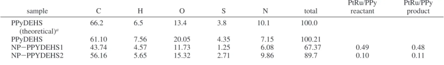
The decrease in the total mass contribution from the C, H, N, and S elements is readily assigned to the presence of Pt and Ru in PPyDEHS samples. In the case of the NP-PPyDEHS1 sample C, H, and N concentrations decreased by only 30, 40, and 15% respectively, whereas S has decreased by nearly 70% when compared to the pristine PPyDEHS sample. A similar trend is also observed in the NP-PPyDEHS2 sample. The larger sulfur loss is probably due to a loss of the DEHS dopant. It is indeed easier for the hydrogen-bonded DEHS to dissociate from the main polymer structure than the covalently bonded pyrrole monomer, especially in a polar solvent. It is possible that this decrease may have occurred during nanopar-ticle preparation involving high-temperature reflux (163 °C), although TGA showed that the sample is stable up to 200°C. TABLE 1: Percentage of Mass Concentration of C, H, O, S, and N in Three PPyDEHS Based Samples
sample C H O S N total PtRu/PPyreactant PtRu/PPyproduct
PPyDEHS (theoretical)a 66.2 6.5 13.4 3.8 10.1 100.0 PPyDEHS 61.10 7.56 20.05 4.35 7.15 100.21 NP-PPYDEHS1 43.74 4.57 11.73 1.25 6.08 67.37 0.49 0.48 NP-PPYDEHS2 56.16 5.65 15.32 2.71 9.86 89.7 0.10 0.11
aTheoretical estimation of the PPyDEHS composition is based on a reported structure.34
Unfortunately the loss of dopant may have an adverse effect on the conductivity of the polymer matrix.
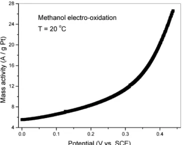
Electrocatalytic activity of three different electrodes contain-ing NP-PPyDEHS colloids have been accessed by measurcontain-ing the current-voltage (I-V curves) at room temperature. Figure 4 shows the electro-oxidation data for the first electrode (E1) prepared from NP-PPyDEHS1 colloidal solution with an estimated platinum load of 50 µg. This figure shows that a good catalytic activity is observed even at room temperature. Much higher levels of catalytic activity are expected at higher temperatures.
The effects of polymer and metal content are also studied. A second electrode (E2) is prepared with the same colloidal solution (NP-PPyDEHS1) used for E1. As summarized in Table 2, lower catalytic activity is observed on electrode E2 containing an estimated platinum amount of 16 µg. Load estimation is based on the starting material composition. It is worth noting that while the load has decreased by a factor of 3, the activity measured by the area current density has decreased by a factor of nearly 10. The presence of a relatively large concentration of polymer may also lead to catalyst site blocking.
A third electrode (E3) is prepared using NP-PPyDEHS2 colloidal solution. This second colloidal solution contains 5 times less Pt than PPyDEHS1. The estimated total Pt deposited on this third electrode is 50 µg. The level of catalytic activity measured on this electrode is much lower that the previous two. It is possible that the high concentration of DEHS dopant containing sulfur may have caused catalyst poisoning. Indeed the strong metal-sulfur chemisorption is probably favored by the presence of a large amount of sulfur during nanoparticle preparation at 163 °C. Furthermore, the presence of a large amount of sulfur during reaction may lead to saturation of the
metal surface sites, leading to significant catalyst poisoning. On the basis of sulfur and metal concentration reported in Table 2, the mass concentration ratio Pt-Ru/S is estimated to 18.9 and 3.8 for NP-PPyDEHS1 and NP-PPyDEHS2, respectively.
Several factors may need to be optimized to increase the catalytic activity of these novel materials. For example, we need to have a better control of nanoparticle distribution within the polymer matrix during nanoparticle preparation and during deposition on the electrode. Non-sulfur-containing conducting and soluble polymers will probably need to be used, although they are not always easy to synthesize.27Choi et al.25recently showed that Pt-Ru nanoparticles dispersed in poly(N-vinyl-carbazole) and poly(9-(4-vinylphenyl)poly(N-vinyl-carbazole) have some potential for DMFC applications. However, the low conductivity of these two polymers may have contributed to lower catalytic activity when compared to carbon black-supported catalyst.25 4. Conclusion
A scalable fabrication process of polymer-imbedded Pt-Ru nanocatalysts for DMFC applications is described in this paper. This process is easily adapted to any conductive polymer soluble in polar organic solvents. The microwave synthesis involves a first step of microwave heating for 3 min at 163°C followed by a second step of solvent cleaning. Only benign solvents have been used. Although good catalytic activities are measured at room temperature, the presence of a sulfur-containing dopant and/or high concentration of polymer may have contributed to lower catalytic activity.
References and Notes
(1) Dillon, R.; Srinivasan, S.; Arico`, A. S.; Antonucci, V. J. Power
Sources 2004, 127, 112-126.
(2) Wasmus, S.; Ku¨ver, A. J. Electroanal. Chem. 1999, 461, 14-31. (3) Smotkin, E. S.; Diaz-Morales, R. R. Annu. ReV. Mater. Res. 2003,
33, 557-579, and references therein.
(4) Park, G.-G.; Yang, T.-H.; Yoon, Y.-G.; Lee, W.-Y.; Kim, C.-S.
Int. J. Hydrogen Energy 2003, 28, 645-650.
(5) Arico`, A. S.; Baglio, V.; Modica, E.; Di Blasi, A.; Antonucci, V.
Electrochem. Commun. 2004, 6, 164-169.
(6) Sasaki, K.; Wang, J. X.; Balasubramanian, M.; McBreen, J.; Uribe, F.; Adzic, R. R. Electrochim. Acta 2004, 49, 3873-3877.
(7) Mayer, A. B. R. Polym. AdV. Technol. 2001, 12, 96-106. (8) Ralph, T. R.; Hogarth, M. P. Platinum Metals ReV. 2002, 46, 117-135.
(9) Liu, L.; Pu, C.; Viswanathan, R.; Fan, Q.; Liu, R.; Sotkin, E. S.
Electrochim. Acta 1998, 43, 3657-3663.
(10) Ren, X.; Wilson, M. S.; Gottesfeld, S. J. Electrochem. Soc. 1996,
143, L12-L15.
(11) Arico`, A. S.; Creti, P.; Modica, E.; Monforte, G.; Baglio, V.; Antonucci, V. Electrochim. Acta 2000, 45, 4319-4328.
(12) Bock, C.; Paquet, C.; Couillard, M.; Botton, G. A.; Macdougall, B. R. J. Am. Chem. Soc. 2004, 126, 8028-8037.
(13) Han, K. I.; Lee, J. S.; Park, S. O.; Lee, S. W.; Park, Y. W.; Kim, H. Electrochim. Acta 2004, 50, 791-794.
(14) Chain, G. S.; Yoon, S. B.; Kim, J. H.; Yu, J.-S. Chem. Commun.
2004, 2766-2767.
(15) Fujiwara, N.; Yasuda, K.; Ioroi, T.; Siroma, Z.; Miyazaki, Y.
Electrochim. Acta 2002, 47, 4079-4084.
(16) Watanabe, M.; Uchida, M.; Motoo, S. J. Electroanal. Chem. 1987,
229, 395-406.
(17) Rajalakshmi, N.; Ryu, H.; Dhathathreyan, K. S. Chem. Eng. J. 2004,
102, 241-247.
(18) Petrow, H. G.; Allen, R. J. U.S. Patent 3,992,331, 1976, 1-5. (19) Toshima, N.; Yonezawa, T. New J. Chem. 1998, 1179-1201, and references therein.
(20) Toshima, N.; Shiraishi, Y.; Teranishi, T.; Miyake, M.; Tominaga, T.; Watanabe, H.; Brijoux, W.; Bo¨nnemann, H.; Schmid, G. Appl.
Organomet. Chem. 2001, 15, 178-196.
(21) Qi, Z.; Pickup, P. G. Chem. Commun. 1998, 15-16.
(22) Liu, M.; Yu, W.; Liu, H.; Zheng, J. J. Colloid Interface Sci. 1999,
214, 231-237.
(23) Dalmia, A.; Lineken, C. L.; Savinell, R. F. J. Colloid Interface
Sci. 1998, 205, 535-537.
Figure 4. Room-temperature methanol electro-oxidation I-V curve of E1 electrode normalized to the estimated Pt load.
TABLE 2: Summary of the Catalytic Properties of Three Different Electrodesa
electrode colloidal solution
PtRu/PPy ratio Pt load (µg) mass activity A/g @ 0.4 V E1 NP-PPyDEHS1 0.49 50 20 E2 NP-PPyDEHS1 0.49 16 1.8 E3 NP-PPyDEHS2 0.10 50 0.4
aElectrodes E1 and E2 are prepared using the same colloidal solution,
but with a different metal loadings. The metal loadings in electrodes E1 and E3 are similar, but the metal-to-polymer ratio is 5 times lower in E3 than in E1.
(24) Bose, C. S. C.; Rajeshwar, K. J. Electroanal. Chem. 1992, 333, 235-256.
(25) Choi, J.-H.; Park, K.-W.; Lee, H.-K.; Kim, Y.-M.; Lee, J.-S.; Sung, Y.-E. Electrochim. Acta 2003, 48, 2781-2789.
(26) Thiele, H.; von Levern, H. S. J. Colloid Sci. 1965, 20, 679. (27) Oh, E. J.; Jang, K. S.; MacDiarmid, A. G. Synth. Met. 2002, 125, 267-272, and references therein.
(28) Hayes, B. L. In MicrowaVe synthesis: chemistry at the speed of
light; Mathews, N. C., Ed.; CEM Publishing, 2002.
(29) Yu, W.; Tu, W.; Liu, H. Langmuir 1999, 15, 6-9.
(30) Yan, X.; Liu, H.; Liew, K. Y. J. Mater. Chem. 2001, 11, 3387-3391.
(31) Bensebaa, F.; Patrito, N; Le Page, Y.; L’Ecuyer, P.; Wang, D. J.
Mater. Chem. 2004, 14, 3378-3384.
(32) Chen, W.-X.; Lee, J. Y.; Liu, Z. Mater. Lett. 2004, 58, 3166-3169.
(33) Steigerwalt, E. S.; Deluga, G. A.; Lukehart, C. M. J. Nanosci.
Nanotech. 2003, 3, 247-251.
(34) Jang, K. S.; Han, S. S.; Suh, J. S.; Oh, E. J. Synth. Metals 2001,
119, 107-108.
(35) Hills, C. W.; Mack, N. H.; Nuzzo, R. G. J. Phys. Chem. B 2003,
107, 2626-2636.
(36) Bock, C.; MacDougall, B.; Le Page, Y. J. Electrochem. Soc. 2004,
151, A1269-A1278.
(37) Le Page, Y.; Rodgers, J. R. J. Appl. Crystallogr. 2005, 38, 697-705.