Official URL
https://csit.am/2017/Proceedings/ITA/ITA6.pdf
Any correspondence concerning this service should be sent
to the repository administrator:
[email protected]
This is an author’s version published in:
http://oatao.univ-toulouse.fr/22284
Open Archive Toulouse Archive Ouverte
OATAO is an open access repository that collects the work of Toulouse
researchers and makes it freely available over the web where possible
To cite this version: Nivolala, Tiavina Tantely and
Andriamarozakaniaina, Tahiry and Jessel, Jean-Pierre Automatic
Generation of Urban Virtual Environments. (2018) In: 11th
International Conference on Computer Science and Information
Technology (CSIT 2017), 25 September 2017 - 29 September 2017
(Yerevan, Armenia).
Automatic Generation of Urban Virtual Environments
Tiavina Tantely, Nivolala
University of Antananarivo Antananarivo, Madagascar e-mail: [email protected]
Tahiry,
Andriamarozakaniaina
University of Antananarivo Antananarivo, Madagascar e-mail: [email protected]Jean-Pierre, Jessel
Paul Sabatier UniversityToulouse, France
e-mail:
ABSTRACT
This paper presents an approach to automatic city gen-eration relying on the existing set of models. First, a hierarchical database containing the main elements of an urban environment is created, and then procedural techniques are applied in order to generate the environ-ment with the data from the database, for the chosen city. This approach adds randomness while keeping con-trol on the main features of the environment.
Keywords
City generation, 3D database, 3D visualization, virtual worlds, computer graphics, declarative modelling
1.
INTRODUCTION
Urbanization is occurring rapidly, and since 2008, more than half of the world population lives in cities. Those cities inspired a number of resulting urban virtual envi-ronments, and predictably, many new applications be-gan to use them as a platform to integrate numerous information on cities coming from various resources. These environments are used for visualisation and ex-ploration of urban landscapes as well as to assist in vari-ous other tasks as they offer plentiful possibilities in the field of city, traffic or disaster management as well as the creation of virtual worlds.
Models of 3D cities, in an effort to get closer to the real ones, are becoming increasingly complex in terms of spatial and thematic structures. In order to store all this information, standardized data models, ensur-ing consistent and inter-operable data structure, have to be built. On the other hand, all the progress made in computer graphics and hardware enables 3D virtual worlds to be more and more complex visually speaking. As visual quality of video games improves with each new generation of graphics hardware, the user expectations increases proportionally. To manage the display of this quantity of data, a possible alternative to manually cre-ating large amounts of models is to apply procedural techniques, along with the use of a few models. Indeed, a complex city containing many different models would take a long time to build manually, and to minimize the costs of world’s creation, the generation of objects with a procedural approach, not only adds controllable randomness to the world but also gives varied results. Our work is focused on creating a hierarchical database model that contains the basic elements of an urban envi-ronment, and from these data, our system will
automat-ically generate a city respecting the architectural style in the database, which will keep control on the costs of creation and the general appearance of the cities.
2.
RELATED WORKS
Past research has tackled the problem of automatic city generation, each one focusing on a particular aspect. Several standards exist to represent city data : the IFC standard [9] is a file format generally used in the build-ing and construction industry to describe, exchange and share information. One of the most popular data mod-els focusing on cities as a whole is CityGML [7]. The 3DCityDB project [14] aims to reuse the main features of CityGML, while simplifying the complex data model for a more compact database and improve the speed of queries, our model is also largely influenced by the latter. The QUASY model [2] has similarities with CityGML but it adds semantic extensions to the usual basic models.
Another interesting approach is to reconstruct city mod-els from facade photographs [12], to take these facades and generate variations [1], or to use terrestrial scan data [4], laser scanning and digital ground plans [3]. The use of grammars, L-systems in particular, showed successful results in the modeling of plants. Grammars have been extended to the modeling of architecture since the introduction of the shape grammars [15], later, other novel shapes extended this initial grammar, introducing new concepts and operations, namely : the Split Gram-mar [16] CGA Shape GramGram-mar [11].
Procedural methods were used for the CityGen system [10] in order to create cities interactively by direct ma-nipulation of parameters of the generation algorithm via an interactive interface. Undiscovered Worlds [6] gener-ate pseudo-infinite virtual worlds by vertical extrusion of floor plans, which is possible only by generating the visible part of the world at once.
3.
OVERVIEW
We present a system that allows the user to feed the database using custom models for each chosen city and then generate a virtual world respecting this urban style. The creation of this system is done in two steps:
• The design and feeding of the database.
• Procedural generation of cities from this database. The rest of this paper will be structured as follows: in the next section, we describe the methods used for the representation of the main features of cities and the
feeding of the database. Section 5 focuses on the ran-dom generation of cities from these key items. Section 6 presents the results of our system and the last sec-tion concludes the paper and provides some prospects of evolution.
4.
THE DATABASE
4.1
Database design
The database is based on PostgreSQL and its spatial extension PostGIS that adds new geometric and geo-graphic types to the database. It will represent the ge-ometric and thematic aspects of a city. A geographical region will contain a set of cities, and a city is made up of buildings, streets, cars and other items that will be called urban objects, the latter are generic objects which may contain everything that is not a building. The solid model of buildings is geometrically represented using Boundary Representation [8] or BRep. A solid is represented by its bounding surfaces, a surface by its edges, and the edges by vertices defined by 3D coor-dinates. In our case, a simplified model is used: all geometries will be stored as polygons and aggregations of polygons, as any surface-based 3D object contained in the environment may be modeled using these. All spatial objects are built from polygons compositions. Aggregations are done between solid and representative surfaces. We also introduce a table containing appear-ance data (textures and colors which are typical of the city in question) which are attached to geometric sur-faces.
In addition to surface-based elements, we introduce the predefined objects for the cases where a geometrically complex element is instantiated multiple times for one or more buildings. They are 3D models that are first normalized and then stored as such in the database, they will be called each time they should be instantiated in the environment, and each reference will contain the corresponding transformation matrix.
To keep consistency between the entities, the geomet-ric elements are linked with the thematic elements with the same level of hierarchy [13]. The building itself is composed of bounding faces that may contain openings. A building may have other facilities outside (fireplace, balcony ...). Respecting the spatial and semantic con-sistency, buildings are associated with geometric solids, bounding surfaces (walls, roof) and openings (doors, windows) with geometrical surfaces and predefined ob-jects, respectively.
Figure 1. Simplified model of the database’s geometries
4.2
Database feeding
The feeding of the database is done through model in-sertion via Blender and its Python API. The database currently will only contain 2D data, 3D objects are mod-eled using primitives in 2D with 3D coordinates. We will directly use the geometric polygon, as edges or isolated vertices are not representative in a city.
Preliminary operations: Before executing the script that will perform the transition to the database, the user
must manually perform some operations in Blender. All meshes of the same urban object must be grouped. In the case of a building, this group should be assigned a custom property named ’type’ with the value ’building’, this property may be omitted for a generic urban object. In the database, bounding surfaces may contain open-ings, in order to respect this constraint, the openings (doors, windows) must have a parent-child relationship with the bounding surface (wall, roof) they are attached to. All these entities will also have a custom property the value of which will be their function (’wall’, ’roof’, ’door’, ’window’). In case the user does not assign any type or function to the objects in the scene, they will be inserted into the database as generic objects. If an object in a building group has no custom property, the script will assume that this is a building facility and insert it into the corresponding table.
Inserting surface-based objects: The objects are first identified by theme. The solid forming these ob-jects are inserted first. Afterwards, the script retrieves all the object’s thematic components. For the build-ing, meshes that do not have parents are collected first, meaning : roofs and walls, and for each object, an entry in the bounding surface table is inserted. The corre-sponding polygons and their vertices are then retrieved; with this list of vertices, a polygon entry will be inserted into the geometric surface table. Note that whenever we are dealing with a polygon, should it be concave, our script will break it down into a set of smaller and convex polygons, this will serve us later during the gen-eration step. After that, appearance data is extracted from the above multi-surfaces and inserted into the cor-responding tables.
Inserting predefined objects: Children of each bound-ing surface are collected and here comes into play the concept of predefined objects as the same window will often be reused for one or more buildings. Said window is stored only once as a 3D model in the predefined form table under a unique name. Each time it is used, a new table entry is created as a reference to the entry in the predefined form table that uses it, accompanied by a transformation matrix to store the translation, rotation and scale to apply this new instance. All these items are standardized before export.
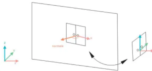
Figure 2. Preparing the predefined object before exporting
Their local center is placed at the center of gravity, their location is moved to the origin of the scene and their local pivot is oriented so that the front face of an open-ing is perpendicular to the x axis. To correctly orient this pivot, we’ll refer to the position of the opening once properly placed against its closing surface. At that time, this opening is properly oriented along the x and y axes to make its front face perpendicular to the x axis, it should rotate around the z axis. The value of the rota-tion angle applied to correct the orientarota-tion is the angle formed between the x axis and the normal of the nearest polygon constituting the wall that is also the parent of
the said opening.
5.
THE CITY GENERATION
The last step is the generation of a simplified city from the database models. This city consists of a street and buildings on both sides of the street. This part is car-ried out with the Unity3D engine. The terrain and the streets are placed first. After querying the base on a particular town, we will get a number of buildings, ur-ban objects and cars.
5.1
Buildings
To each building are attached child elements : bound-ing surfaces which are a composition of convex polygons, and openings: predefined objects accompanied by their transformation matrices. To generate polygon-based el-ements, a simple triangulation is performed using the coordinates of the polygon vertices [5]. Next we deter-mine the UV texture coordinates in order to project a 2D image correctly on the surface of a 3D model by cal-culating the coordinates of the triangles in the image used as the texture attached to the triangles of the 3D object. We can do this by valuing which axis of each polygon must be eliminated so that we can keep only two axes in 2D which are normalized between 0 and 1. As for the predefined objects, they are instantiated at the origin, then the rotation, translation and scale extracted from the transformation matrix are applied before they are attached to the building.
Adjustments on buildings: When a building is gen-erated from a database, we calculate its bounding box to ensure the placement of buildings at random positions while checking for collisions. Next, a pivot is attached to that building. The pivot is positioned in the center of the bounding box, and the x axis is oriented towards a door, because often buildings are oriented in respect to a front door.
Once all database buildings are generated, the existing buildings are cloned and placed on a random, unoccu-pied position on the terrain. Once the clone is placed, we calculate the rotation to be applied to it. We choose the building rotation so that its door is facing the street by default (the x axis of its pivot, previously calculated, points to the street). Lastly, we try to adjust the scale of the resulting building, if necessary, an item that will serve as a reference for comparison to correct the build-ing scale should be chosen. The value of the vertical height of the door was chosen because, out of all the elements of a building, this value is less subject to varia-tion in their style (they must, at least, have a minimum height). However, we allow a margin of more or less 20 % compared to the standard height. The standard height is calculated relative to the only element that was present before any generation: the street and its width. Finally, the new scale applied to the building will have a difference in scale between the standard height of the door and its current height.
Thematic elements: For each building clone placed on the terrain, its thematic elements are selected, and instead other ones are placed selected in the database that belong to the same city and are of the same type. In order to do this, thematic components of the building are individually selected. We start by retrieving bound-ing surfaces which are isolated by type (‘wall’, ‘roof’), and for them, random appearance data is retrieved in the database for the same type of element and with the
selected city. These new appearances are applied to the corresponding surfaces.
We then retrieve the transformation matrix of the build-ing predefined objects by the type (‘door’ and ‘win-dow’), and the predefined objects of the same type are retrieved from the database for the same city and placed instead of the previous predefined object using the ma-trix saved above. The dimensions of the previous open-ing are temporarily stored to prevent any inconsisten-cies and applied to the new opening. The standardiza-tion of their orientastandardiza-tion before export enables the reuse and exchange of their rotations. For openings and espe-cially windows, for each bounding surface of the original building, it is randomly chosen whether or not windows will be attached to it on the condition that at least one bounding surface contains these openings.
5.2
Urban objects and vehicles
Urban objects are generated like buildings, except that they are not decomposed into thematic elements, and are simply composed of polygons and/or predefined items the generation of which has been covered above. They are also generated after the buildings and cover a larger area of the terrain than the latter.
The vehicles are similar to urban objects by their design and extraction from the database. Once all the basic ve-hicle models are selected, they are randomly generated along both sides of the street, facing opposite directions. Once generated they are animated to move towards the end of the street, and once this goal is achieved, they disappear and are regenerated at the beginning of the street, and so on.
6.
RESULTS
Typical buildings of three test cities, each with some common features for their respective buildings and a well-characterized urban style, were inserted into the database : a typical colorful city of Madagascar, an-other American city with skyscrapers with flat roofs and identical windows and a Norway village with wooden walls, stave and tiled roofs, and wooden windows and doors. The terrain and the street were placed first and buildings and urban objects were generated on areas unoccupied by the street.
6.1
Output
Table 1. Geometric elements from the database Region Cities
Build-ings Multi-Surfaces Prede-fined ele-ments Convex Poly-gons Mada-gascar 1 4 10 52 67 America 1 5 5 195 42 Norway 1 6 20 59 120
Table 2. Thematic elements from the database Region Build-ings Urban ob-jects Vehi-cles Bounding sur-faces Open-ings Mada-gascar 4 1 3 25 50 America 5 0 2 25 195 Norway 6 2 2 43 53
Table 3. Generated elements for each city Region Build-ings Bounding sur-faces Vehi-cles Open-ings Facili-ties Mada-gascar 150 900 40 1875 37 America 150 750 40 8325 0 Norway 150 1200 40 1325 148
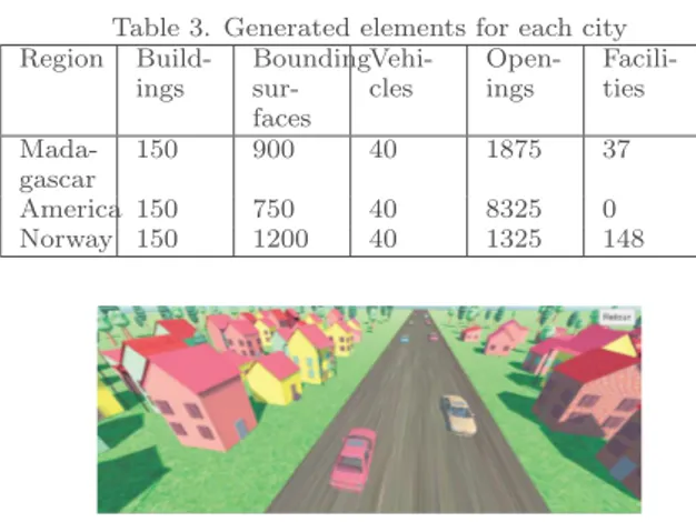
Figure 3. Screenshot of a town from Madagascar
Figure 4. Screenshot of a town from Norway
Figure 5. Screenshot of an American city
We can see that despite applying the variations, the general style of the cities remains faithful to the overall styles of the individual buildings. The more contrast be-tween colors, textures and overall shape of buildings, for example, in Antananarivo, the more the resulting city looks disparate, contrarily to the Norway town, which seems more uniform.
7.
FUTURE WORK
We presented a system capable of generating a city from a set of predefined elements for each urban style of in-serted cities. The work we have done so far was focused on a method that associates the use of a database of ur-ban models and a procedural method for the visualiza-tion of a city, and our contribuvisualiza-tions have been focused on this hybrid approach, using the coupling between static elements, and the models created manually, and then using procedural methods on these elements to de-compose these models and create cities containing var-ious items, while keeping some control and respecting the urban style of it. We were able to model and gener-ate random cities, exchanging architectural elements in order to obtain variations on an infrastructure, as well as ensuring that the number of models stored in the database is reduced to a minimum. While this system can play a useful role in the construction of an urban model, this is achieved through compliance with estab-lished standards and good initialization when modeling. And thus, the system still has gaps and future research can be suggested in the following areas :
The first perspective of evolution is to further automate the model’s import into the database, so as to avoid having to manually name the descriptive elements of a building, an algorithm should be developed capable to recognize the thematic elements from distinct character-istics such as the position relative to certain components and, thus, reduce the user’s tasks to a minimum. It would also be useful to integrate other thematic el-ements into the category of urban objects, as well as for the buildings themselves. Buildings could be clas-sified by function (e.g., residential, commercial, indus-trial) and their creation and placement follow a number of rules to ensure the coherence of the whole environ-ment. In our future works, the procedural aspect will be explored in more depth, we especially consider taking in an amount of input data in order to extract derivation rules, our database could then consist of primary shapes to use these rules on.
Finally, the system should consider a more complex street network which could be done via input data on the street patterns and other information about the ter-rain pertaining to the streets shape.
References
[1] F. Bao, M. Schwarz, et al. “Procedural facade variations from a single layout”. 2013.
[2] J. Benner, A. Geiger, et al. “Flexible generation of semantic 3D building models”. 2005.
[3] C. Brenner. “Towards fully automatic generation of city models”. 2000.
[4] C. Dold and C. Brenner. “Automatic matching of terrestrial scan data as a basis for the generation of detailed 3D city models”. 2004.
[5] A. Fournier and D. Y. Montuno. “Triangulating simple polygons and equivalent problems”. 1984. [6] S. Greuter, J. Parker, et al. “Undiscovered worlds–
towards a framework for real-time procedural world generation”. 2003.
[7] G. GROGER, T. H. Kolbe, et al. Open Geospatial Consortium OGC City Geography Markup Lan-guage (CityGML) Encoding standard. 2012. [8] J. F. Hughes, A. Van Dam, et al. Computer
graph-ics: principles and practice. 2014. [9] Industry Foundation Classes.
[10] G. Kelly and H. McCabe. “Citygen: An interactive system for procedural city generation”. 2007. [11] P. M¨uller, P. Wonka, et al. “Procedural modeling
of buildings”. 2006.
[12] P. M¨uller, G. Zeng, et al. “Image-based procedural modeling of facades”. 2007.
[13] A. Stadler and T. H. Kolbe. “Spatio-semantic co-herence in the integration of 3D city models”. 2007.
[14] A. Stadler, C. Nagel, et al. “Making interoper-ability persistent: A 3D geo database based on CityGML”. 2009.
[15] G. Stiny. “Introduction to shape and shape gram-mars”. 1980.
[16] P. Wonka, M. Wimmer, et al. Instant architecture. 2003.