B e s t P r a c t i c e G u i d e o n F i r e S t o p s a n d F i r e
B l o c k s a n d t h e i r I m p a c t o n S o u n d
T r a n s m i s s i o n
N R C C - 4 9 6 7 7
R i c h a r d s o n , J . K . ; Q u i r t , J . D . ; H l a d y , R .
J u n e 2 0 0 7
J u n e 2 0 0 7
Best Practice Guide on Fire Stops
and Fire Blocks and their Impact
on Sound Transmission
J.K. Richardson, J.D. Quirt, R. Hlady
Best Pr
actice Guide on Fir
e Stops and Fir
e Bloc
ks and their Impact on Sound T
ransmission
BEST PRACTICE GUIDE ON FIRE STOPS AND FIRE BLOCKS
AND THEIR IMPACT ON SOUND TRANSMISSION
Prepared For
Special Interest Group on Suitable Acoustic and
Fire Stop Technologies
Prepared by
DISCLAIMER
The analysis, interpretations, and recommendations in this Guide are those of the authors and do not necessarily reflect the views of the Special Interest Group on
Suitable Acoustic and Fire Stop Technologies or those organizations that assisted in the preparation, review and publication of the document.
Care has been taken to review the literature summarized in this Guide. Neither the authors nor the Special Interest Group warrant or assume any liability for the accuracy or completeness of the text or drawings, or their fitness for any particular purpose. It is the responsibility of the user to apply professional knowledge in the use of the information contained in the drawings and text, to consult original sources, or when appropriate, to consult a qualified design professional.
BEST PRACTICE GUIDE ON FIRE STOPS AND FIRE BLOCKS AND THEIR IMPACT ON SOUND TRANSMISSION
(A Publication of the Special Interest Group on Suitable Acoustic and Fire Stop Technologies)
PREFACE
The production of the Best Practice Guide was organised by the National Research Council of Canada (NRCC) and Ken Richardson Fire Technologies Inc. (KRFT). Unless otherwise indicated, all drawings have been provided by Affinity Fire Stop Consultants Inc.
This Best Practice Guide is based extensively on a document from The City of Calgary entitled “Fire Stopping Service Penetrations in Buildings”, and the authors extend their appreciation to the City for making the document available and for assistance in development of this Guide.
Critical review of the content of the Best Practice Guide was the primary focus of the Special Interest Group on Suitable Acoustic and Fire Stop Technologies (SIG-SAFT). This Special Interest Group (SIG) was made up of stakeholders, who provided financial and in-kind support for the project, as well as regulators and standards
developers. The SIG provided review and comment on draft documents to NRCC and KRFT throughout the production process. A formal ballot of SIG members confirmed acceptance of the final content.
The organizations and individuals comprising SIG-SAFT are:
Organizations Individual
3M Canada Sylvain Masse
Marcelo Mellicovsky
A/D Fire Protection Systems Don Falconer
Affinity Fire Stop Consultants Inc. Rob Hlady
Bibby Ste. Croix William Monaghan
Preface - 2
Organizations Individual
Hilti Canada Corporation Douglas King
International Firestop Council Anthony Crimi
IPEX Inc. Allan Baker
Ken Richardson Fire Technologies Inc. Ken Richardson
NRCC – Institute for Research in Construction David Quirt
North American Insulation Manufacturers Association Keith Wilson
John Scott
NUCO Inc. Keith Brebner
Ontario Ministry of Municipal Affairs & Housing John Gryffyn
Cengiz Kahramanoglu
The City of Calgary Bernardine van der Meer
Tremco Inc. Rick Reuss
Underwriters' Laboratories of Canada Emmanuel Sopeju
The draft document was also circulated to external reviewers to obtain input from potential users who were not involved in the development of the Guide. The following individuals reviewed the draft and provided comment to the SIG and the authors.
Organization Individual
NRCC – IRC – Canadian Codes Centre Igor Oleszkiewicz
Senez, Reed, Calder Fire Engineering Inc. Peter Senez
Gibbs Gage Architects Ed Sych
Thermo Fire Systems Inc Mike McClure
Participation of organizations and individuals from both Canada and the U.S.A. helped to ensure that the input encompassed the codes, standards and regulatory environments in both countries.
This Best Practice Guide primarily addresses fire stops and fire blocks installed in Canada, which must meet Canadian codes and standards. The requirements for fire stops and fire blocks in the National Building Code of Canada (NBCC) are similar, in concept, to those contained in the International Building Code (IBC) and NFPA 5000 in the U.S.A. Specific significant differences between Canadian and American codes are identified. The current requirements for CAN/ULC-S115 also contain a number of differences from the American Society of Testing and Materials (ASTM) and
Underwriters Laboratories Inc. (UL) documents in the U.S.A; these are also identified in the Guide.
The Guide also identifies differences from the NBCC that have been approved in some provincial building codes. These are included to ensure that users of the Guide are aware of the minor provincial variations that may impact on fire stops and fire blocks.
The Guide has been developed to assist in the design, installation and inspection of suitable fire stop and fire block systems. It is intended to identify technical solutions relating to the fire resistance and sound transmission aspects of fire stops and fire blocks by those who manufacture, design, specify, install and inspect these systems.
The Best Practice Guide is not intended for use as a code document. Some of the solutions described in the Guide may not conform specifically to current Canadian codes. The authority having jurisdiction must be consulted on the acceptance of such solutions. The Guide, however, may be used as a background reference by those in the building regulatory community as a means of identifying suitable fire and acoustic
solutions for fire stops and fire blocks. In the future, others may re-work the Best Practice Guide, or portions of it, into a form that may be suitable for use with codes and standards. That is not the intent of this current document, however. While the Guide makes extensive reference to the NBCC as being the source of the requirements for fire stops and fire blocks in Canada, there are occasions in the Guide where Best Practice may dictate the need for features beyond the NBCC requirements. The authors have tried to identify those situations in Chapters 7 through 13.
Contents - 1 TABLE OF CONTENTS DISCLAIMER... PREFACE ... 1.0 INTRODUCTION... 1.1 Background ... 1.2 Objective... 1.3 Basic Terminology ...
1.4 Historical Requirements for Fire Stops and Fire Blocks ...
1.5 The Effects of Fire Stops and Fire Blocks on Acoustic Separation
of Spaces... Chapter 1 References ...
2.0 BASICS OF FIRE COMPARTMENTATION AND SOUND TRANSMISSION
2.1 Fire Compartmentation History...
2.2 Elements of Fire Compartmentation...
2.3 Protection of Openings In and Between Fire Separations...
2.4 Concealed Spaces in Construction ...
2.5 Effect of Fire Stops and Fire Blocks on Acoustical Separation ...
2.6 Rating Sound Transmission Through Fire Stops...
2.7 Cases where STC Ratings are not Required for Fire Stops ...
2.8 Other Noise Control Objectives ...
Chapter 2 References ...
3.0 TYPES OF FIRE STOPS AND FIRE STOP MATERIALS ...
3.1 Introduction...
3.2 Fire Stop Materials ...
3.3 Through-Penetration Fire Stops ...
3.4 Membrane-Penetration Fire Stops ...
3.5 Construction Joint Fire Stops ...
3.6 Building Perimeter Fire Stops...
3.7 Caulks and Sealants...
3.8 Putties...
3.9 Mortars and Grouts...
3.10 Foams...
3.11 Coatings and Sprays ...
3.12 Wraps ...
3.13 Blocks, Pillows and Bags...
3.14 Composite Sheets and Boards...
3.15 Fire Stop Devices ...
3.16 Generic Materials ...
4.0 TYPES OF FIRE BLOCKS AND FIRE BLOCK MATERIALS ...
4.1 Introduction...
4.2 Concealed Space Division...
4.3 Fire Block Materials ...
Chapter 4 References ...
5.0 CODE REQUIREMENTS FOR FIRE STOP INSTALLATIONS AND SOUND ISOLATION...
5.1 Introduction...
5.2 NBCC Requirements for Continuity of Fire Separations ...
5.3 NBCC Requirements for Protection of Service Penetrations ...
5.4 NBCC Requirements for Sound Control...
5.5 Rating of Fire Stops for Service Penetrations ...
5.6 Requirements of CAN/ULC-S115...
5.7 U.S. Model Code Requirements for Fire Stops (including
Sound Control) ... Chapter 5 References ...
6.0 CODE REQUIREMENTS FOR FIRE BLOCK INSTALLATIONS AND SOUND ISOLATION...
6.1 Introduction...
6.2 NBCC Requirements for Fire Blocks in Concealed Spaces ...
6.3 Rating of Fire Blocks ...
6.4 U.S. Model Code Requirements for Fire Blocks and Draft Stops ...
6.5 Requirements for Sound Control ...
Chapter 6 References ...
7.0 BASIC ISSUES RELATED TO BEST PRACTICE FOR FIRE STOPS AND FIRE BLOCKS ...
7.1 Engineering Judgements...
7.2 Fire Separations and Fire “Walls” above Parking Garages – F and FT
Ratings ...
7.3 Abandoned Openings Requiring Protection ...
7.4 Multiple Penetrating Items ...
7.5 Minimum Stud (Framed) Wall Plate or Track Size for Penetrating
Items...
Contents - 3
8.0 BEST PRACTICE FOR FIRE STOPS FOR PIPE PENETRATIONS ...
8.1 Introduction...
8.2 Pipe Penetrations through Monolithic Concrete Floor Assemblies...
8.3 Floor Penetrations for Toilets above Monolithic Concrete Floor
Assemblies ...
8.4 Monolithic Concrete Floor Penetrations for Tubs and Showers ...
8.5 Pipe Penetrations through Framed Floor Assemblies ...
8.6 Pipe Penetrations through Framed Floor Assemblies for Toilets ...
8.7 Pipe Penetrations through Framed Floor Assemblies for Tubs and
Showers...
8.8 Pipe Penetrations through Monolithic Concrete or Masonry Walls ....
8.9 Pipe Penetrations through Stud Walls...
8.10 Pipe Penetrations through Framed Roof Spaces ...
8.11 Multiple Pipe Penetrations...
8.12 Transitions between Combustible and Noncombustible Pipe ...
Chapter 8 References ...
9.0 BEST PRACTICE FOR FIRE STOPS FOR ELECTRICAL SERVICE
PENETRATIONS ...
9.1 Introduction...
9.2 Electrical Service Penetrations through Monolithic Concrete Floor
Assemblies ...
9.3 Electrical Service Penetrations through Framed Floor Assemblies....
9.4 Electrical Service Penetrations through Monolithic Concrete or
Masonry Walls ...
9.5 Electrical Service Penetrations through Stud Wall Assemblies ...
9.6 Cable Tray Penetrations...
Chapter 9 References ...
10.0 BEST PRACTICE FOR FIRE STOPS FOR MECHANICAL SERVICE PENETRATIONS ...
10.1 Introduction...
10.2 Mechanical Service Penetrations through Monolithic Concrete
Floor Assemblies ...
10.3 Mechanical Service Penetrations through Framed Floor Assemblies
10.4 Mechanical Service Penetrations through Monolithic Concrete or
Masonry Walls ...
10.5 Mechanical Service Penetrations through Framed Stud Wall
Assemblies ...
10.6 Duct Penetrations and Vertical Shafts...
11.0 BEST PRACTICE FOR FIRE STOPS FOR CONSTRUCTION JOINTS ...
11.1 Introduction...
11.2 Fire Stops for Bottom of Wall Joints ...
11.3 Fire Stops for Top of Wall Joints ...
11.4 Fire Stops between Adjacent Floors...
11.5 Fire Stops between Adjacent Walls...
11.6 Floor-to-Wall Fire Stops...
Chapter 11 References ...
12.0 BEST PRACTICE FOR BUILDING PERIMETER FIRE STOPS ...
12.1 Introduction...
12.2 Best Practice for Building Perimeter Fire Stops with Fire-Rated
Exterior Walls ...
12.3 Best Practice for Building Perimeter Fire Stops with Non-Fire-Rated
Exterior Walls ... Chapter 12 References ...
13.0 BEST PRACTICE FOR FIRE BLOCKS ...
13.1 Introduction...
13.2 Fire Blocks in Wall Assemblies...
13.3 Fire Blocks in Horizontal Concealed Spaces...
13.4 Fire Blocks Between Horizontal and Vertical Concealed Spaces ...
13.5 Fire Blocks Between Nailing Elements...
List of Figures - 1
LIST OF FIGURES
FIGURE 2.A Example of some typical paths for sound transmission
FIGURE 3.A Example of a through-penetration fire stop
FIGURE 3.B Example of membrane penetration fire stop
FIGURE 3.C Example of shaft wall penetration fire stop
FIGURE 3.D Example of construction joint fire stop
FIGURE 3.E Example of building perimeter fire stop
FIGURE 3.F Examples of a fire stop sealant with insulation
FIGURE 3.G Example of fire stop sealant without insulation
FIGURE 3.H Example of a self-levelling fire stop sealant
FIGURE 3.I Example of a mouldable putty fire stop
FIGURE 3.J Example of a putty pad
FIGURE 3.K Example of a fire stop mortar
FIGURE 3.L Example of a fire stop foam
FIGURE 3.M Example of a fire stop spray
FIGURE 3.N Example of a fire stop wrap
FIGURE 3.0 Example of fire stop pillows, blocks or bags
FIGURE 3.P Example of a composite sheet fire stop
FIGURE 3.Q Example of a fire stop collar
FIGURE 3.R Example of a fire stop collar
FIGURE 3.S Example of fire stop plug
FIGURE 3.T Example of electrical box insert
FIGURE 4.A Fire block dividing roof concealed space
FIGURE 4.B Example of fire block separating two concealed spaces
FIGURE 5.A Protection of a penetration by a structural member
FIGURE 5.B Certification Marks used in Canada
FIGURE 6.A Fire block locations and materials
FIGURE 6.B Fire block locations and materials
FIGURE 7.A Example of a blank opening fire stop system
FIGURE 7.B Minimum spacing for multiple pipes when fire stops do not have spacing requirements specified in the listing
FIGURE 7.C Minimum spacing for electrical cables when fire stops do not have spacing requirements specified in the listing
FIGURE 7.D Minimum spacing for openings for penetrations through stud walls
FIGURE 8.A Apartment building over a parking garage showing typical penetrations of combustible and noncombustible piping through rated fire separations
FIGURE 8.B.1 Insulated noncombustible pipe penetration through fire-rated floor system
FIGURE 8.B.2 Insulated combustible pipe penetration through a fire-rated floor assembly
List of Figures - 3
FIGURE 8.G Penetration for toilet on wood sleeper floor system installed above a monolithic concrete slab – F or FT rating
FIGURE 8.H Pipe penetration for a tub or shower above a monolithic concrete slab – F or FT rating
FIGURE 8.I.1 Pipe penetration through a framed floor assembly
FIGURE 8.I.2 Penetration of combustible sprinkler piping through a framed floor assembly
FIGURE 8.J.1 Penetration of sprinkler piping through ceiling membrane of a fire-rated assembly
FIGURE 8.J.2 Penetration of sprinkler piping through ceiling membrane of a fire-rated assembly with a fire stop
FIGURE 8.K Penetration of DWV pipe for a toilet through a framed floor assembly
FIGURE 8.L Penetration of DWV pipe for tubs or showers through a framed floor assembly
FIGURE 8.M.1 Penetration of pipe through monolithic concrete wall assembly
FIGURE 8.M.2 Penetration of pipe through masonry wall assembly not using a sleeve
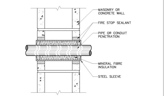
FIGURE 8.M.3 Penetration of pipe through masonry wall assembly using a sleeve
FIGURE 8.N Penetration of water supply pipe through membrane of wall assembly
FIGURE 8.O.1 Penetration of a combustible pipe through a fire-rated wall assembly
FIGURE 8.O.2 Penetration of a noncombustible pipe through a fire-rated wall assembly
FIGURE 8.P.1 Penetration of a pipe through a wall membrane that is not fire-rated
FIGURE 8.P.2 Penetration of a pipe through a fire-rated wall assembly
FIGURE 8.Q Penetration of a drain pipe through a furred-out wall assembly
FIGURE 8.R Penetration of pipe through fire-rated ceiling membrane
FIGURE 8.S Multiple pipe penetrations through a fire-rated stud wall
FIGURE 8.U Combustible DWV pipe penetrating a vertical fire separation
FIGURE 8.V Pipe transition from combustible pipe in the parking garage below the slab to noncombustible pipe above the slab
FIGURE 9.A Typical apartment building showing electrical service penetrations
FIGURE 9.B Example of stacked electrical rooms
FIGURE 9.C Cable penetrations of a monolithic concrete floor assembly
FIGURE 9.D Conduit penetration of a monolithic concrete floor assembly
FIGURE 9.E Cables penetrating monolithic concrete floor above an electrical service room to obtain FT rating in lieu of FT-rated fire stop systems
FIGURE 9.F Fire stops for cables and conduit penetrating a steel framed floor assembly
FIGURE 9.G.1 Fire stops for outlet boxes in fire-rated framed ceiling assemblies
FIGURE 9.G.2 Fire stops for outlet boxes in fire-rated steel-framed ceiling assemblies
FIGURE 9.H Fire stops for outlet box in a dropped ceiling below a fire-rated framed floor/ceiling assembly
FIGURE 9.I Electrical service penetrations through monolithic concrete or masonry wall
FIGURE 9.J Examples of combustible and noncombustible conduit installations for electrical service penetrations through a stud wall
FIGURE 9.K Examples of electrical cable without conduit, at penetrations through a stud wall assembly
List of Figures - 5
FIGURE 10.A Typical apartment building showing mechanical service penetrations of fire-rated assemblies
FIGURE 10.B Example of a fire damper in a fire-rated stud wall assembly
FIGURE 10.C Example of fire stops at a duct penetration that does not require a fire damper
FIGURE 10.D Example of ducts penetrating a monolithic concrete floor assembly
FIGURE 10.E Example of duct penetrations of a monolithic concrete floor assembly with and without fire dampers
FIGURE 10.F Example of chimney penetration in basement with shaft enclosure
FIGURE 10.G Example of chimney penetration in basement with no shaft enclosure below floor
FIGURE 10.H Examples of duct penetrations of a framed floor assembly – with and without fire dampers
FIGURE 10.I Example of duct running through a horizontal space below a framed fire-rated floor assembly
FIGURE 10.J.1 Example 1 of duct running perpendicular to framing members within a fire-rated floor assembly
FIGURE 10.J.2 Example 2 of duct running perpendicular to framing members within a fire-rated floor assembly
FIGURE 10.K.1 Example 1 of duct running parallel to framing members within a fire-rated floor assembly
FIGURE 10.K.2 Example 2 of duct running parallel to framing members within a fire-rated floor assembly
FIGURE 10.L Example of duct penetration of a monolithic concrete or masonry wall with and without fire dampers
FIGURE 10.M.1 Example of duct located in a fire-rated stud wall assembly
FIGURE 10.M.2 Example of duct located in a non fire-rated stud wall assembly
FIGURE 10.N Example of duct located in a furred-out stud wall assembly
FIGURE 10.O Examples of duct penetrations of a fire-rated stud wall assembly with and without fire dampers
FIGURE 10.P Example of ducts penetrating fire-rated vertical shaft wall assemblies
FIGURE 10.Q Example of ducts penetrating fire-rated vertical shaft with a constantly-running fan at the top
FIGURE 10.R Examples of ducts penetrating a fire-rated vertical shaft with ducts continuous to the outside
FIGURE 11.A Types of construction joints
FIGURE 11.B Example of fire stop at bottom of wall
FIGURE 11.C Example of fire stop at top of wall
FIGURE 11.D Examples of fire stops at top of wall, for the joint between a masonry wall and the underside of a fluted steel deck
FIGURE 11.E Track and slip fire stops at top of wall
FIGURE 11.F Fire stop at both joist penetration of the wall and top of wall linear joint
FIGURE 11.G Example of floor-to-floor fire stop
FIGURE 11.H Examples of wall-to-wall fire stops
FIGURE 11.I Example of fire stop between floor and wall
FIGURE 12.A Building perimeter fire stop at a fire-rated concrete or masonry exterior wall
FIGURE 12.B Building perimeter fire stop at a fire-rated exterior stud wall
FIGURE 12.C Building perimeter fire stop with stiffback angle
FIGURE 12.D Proper installation of mineral fibre insulation
List of Figures - 7
FIGURE 13.D.1 Floor/wall cavity where fire block is not required because air gap is 25 mm or less wide
FIGURE 13.D.2 Floor/wall cavity less than or equal to 25 mm wide with fire block
FIGURE 13.D.3 Floor/wall cavity less than or equal to 25 mm wide, with non-fire-rated floor
FIGURE 13.E.1 Examples of fire blocks at ceiling and floor levels with floor/wall cavity greater than 25 mm wide
FIGURE 13.E.2 Examples of fire blocks at ceiling and floor levels with air gap greater than 25 mm wide
FIGURE 13.F Example of fire block at floor level with an air gap greater than 25 mm wide on non-rated floor assembly
FIGURE 13.G Fire blocks in crawl spaces
FIGURE 13.H Fire blocks in roof spaces
FIGURE 13.I Fire blocks in horizontal concealed spaces
FIGURE 13.J Fire block for coved ceiling space
FIGURE 13.K Fire block at ceiling soffit/bulkhead
FIGURE 13.L Fire blocks for stair stringers
FIGURE 13.M Fire block continuity with stair stringers
FIGURE 13.N Fire blocks between ceiling nailing elements in buildings required to be of noncombustible construction
FIGURE 13.0 Fire blocks with raised platform in buildings required to be of noncombustible construction
1.0 INTRODUCTION 1.1 Background
While the past decade has produced valuable research information and technical solutions on suitable fire and acoustic components for fire-resistant wall and floor
assemblies tested in a laboratory, the design and construction process also demands proven approaches to ensure satisfactory performance of installed fire-rated assemblies in buildings. This means addressing potential openings in or adjacent to these floors and walls. As well, recent research conducted at the National Research Council of Canada has shown that construction solutions that provide adequate fire resistance may not resolve (or may worsen) sound transmission shortcomings. Finding suitable fire and acoustic solutions and balancing fire resistance and sound transmission issues are growing problems for all in the construction industry as both are mandated by Codes for certain building occupancies.
For designers, plan reviewers, installers and inspectors, the lack of recognized solutions to provide both appropriate sound and fire control with fire stops and fire blocks is a frequently-encountered problem. As a result of the absence of reliable authoritative documents, accepted practice for fire stop and fire block solutions in one jurisdiction may be unacceptable in neighbouring ones. Those who design and install fire stop systems do not wish to face the problem of having met the fire requirements but not meet the requirements for sound isolation, especially when this is discovered at the
commissioning stage. The manufacturers of fire stop and fire block systems, who provide technical information to designers, installers and regulators, also wish to assure themselves that they have addressed both the fire and sound transmission aspects of their systems to avoid problems that may only be identified at the commissioning stage or during the occupancy of the building.
There is currently no reliable reference document that addresses both fire and sound transmission issues related to fire stops and fire blocks. As well, there is currently no document that provides the design, regulatory, manufacturing and installation
communities with reliable information that can be used with assurance across the many jurisdictions in the country. Much of the technical knowledge needed to produce such a document is presently available in a variety of references. This "Best Practice Guide" aspires to serve as a first reliable reference document.
Best Practice - For the purposes of this Guide, "best practice" is defined as:
Best Practice – Based on current knowledge, recommendations in this Guide representing the best judgement of individuals from all aspects of the
Introduction 1-2
City of Calgary Experience – In the late 1990s, the City of Calgary was experiencing a building boom which included a large increase in the construction of multi-family housing units. During the same period, the City entered into a partnership agreement with the Calgary Region Home Builders' Association to, among other goals, raise standards and to achieve a higher level of consistency in construction of multi-family housing. The City's Building Regulations Division had identified multi-multi-family buildings as their greatest area of concern and had noted a pattern of deficiencies in fire separations and fire stops. The City and its partners from the building industry,
architects, engineers, contractors and fire stop manufacturers agreed that, to reduce deficiencies in the field and obtain a higher standard of consistency, a guideline on fire stops needed to be prepared.
The City of Calgary also noted that numerous new fire stop products were being introduced to the Canadian market and installed in buildings in Calgary. The City had concerns about the selection of appropriate products and their suitable installation in buildings, in particular, multi-unit residential units. Following a two-year development and review process, the guideline "Fire Stopping Service Penetrations in Buildings" [1-1] became a reality in 2003. Subsequently, the City expressed an interest in extending the document to address fire blocks and other fire stops not previously addressed, as well as sound transmission issues, which are often inseparable from fire separation issues in residential buildings. The City’s document and request became the catalyst for the development of this Best Practice Guide.
1.2 Objective
With the numerous reference sources available, this Best Practice Guide will build on existing knowledge and then add value through the integration of the data on fire and sound transmission in such a manner that the user has a useful, authoritative document. With these thoughts in mind, the Objective of the document is:
"To describe, using a synthesis of available data, the technical solutions
necessary to obtain, with fire stop systems and fire blocks, appropriate fire and sound control in buildings."
1.3 Basic Terminology
A number of words and phrases are currently used to describe what is
generically known as "fire stopping". In common usage, the terms "fire stop", "fire block" and "draft stop" are often used interchangeably; others attribute specific meanings to each term. For example, in the 2005 edition of the National Building Code of Canada (NBCC) [1-2], while there is no definition of the term "fire stop", the terms "fire stop" or "fire stop system" are used to encompass all such materials and systems, including those commonly called "fire blocks" or "draft stops" in other documents. There are, however, differences, often not subtle, that call for unique terminology for each different technology. For this reason, in this Best Practice Guide, specific terminology will be
adopted in an attempt to enable the user to better understand what is being discussed, to reduce confusion and to achieve consistency with other North American documents.
Fire Stop – a material, component or system, and its means of support, used to fill gaps between fire separations, between fire separations and other construction assemblies, or used around items which wholly or partially penetrate fire separations, to restrict the spread of fire and often smoke thus maintaining the integrity of a fire separation.
Fire Block – a material, component or system installed in a concealed space in a building to restrict the spread of fire and often smoke in that concealed space, or from that concealed space to an adjacent space.
In this Guide, fire block is intended to encompass the term “draft stop” which is sometimes used in American codes when speaking of some fire blocks in larger
concealed spaces. Draft stops are intended to stop air movement as well as fire spread. In the 2005 NBCC, fire blocks, as defined in this Guide, are called "fire stops".
The basis for the "fire stop" and "fire block" terminology can be found in the Fire Protection Handbook [1-3], NFPA 5000 – Building Construction and Safety Code [1-4] and the International Building Code [1-5]. The Fire Protection Handbook is one of the most widely-used reference documents in the fire protection profession; its use of the
above terminology (fire stop and fire block) in its 19th edition indicates a wide acceptance
internationally of this terminology.
Throughout this Guide, reference is made to "listed fire stop systems". These are systems which have been tested to CAN/ULC-S115 – Standard Method of Fire Tests of Firestop Systems [1-6] by a recognized testing agency and proof of that testing and subsequent follow-up service is provided by an independent certification agency. The definition for a "listed fire stop system" is adapted from CAN/ULC-S115 as follows: In this Guide, "listed fire stop systems" will be used to indicate fire stops which conform to CAN/ULC-S115.
Listed Fire Stop System – a specific construction consisting of materials, any penetrating items and their means of support, that has met the requirements for an F, FT, FH and/or FTH rating when tested in a fire-resistance rated assembly in accordance with CAN/ULC-S115 – Standard Method of Fire Tests of Firestop Systems.
It should be noted that under the NBCC [1-2], Part 3 requires that fire stops comply with CAN/ULC-S115, which may be accomplished by using a listed fire stop
Introduction 1-4
1.4 Historical Requirements for Fire Stops and Fire Blocks
1.4.1 Introduction
The need for fire stops to ensure the continued integrity of fire compartments, and the need for fire blocks to restrict the size of concealed spaces has been known in the fire protection profession since fire compartmentation began to be used as a means of fire control. Historically, fire losses were much greater when fire stops and fire blocks were not installed or were installed with deficiencies. Fire departments frequently reported that fire suppression operations were made more difficult by the spread of fire to an adjacent compartment or to a concealed space as a result of no or poorly-installed fire stops and fire blocks. High profile fires, such as at the Brown's Ferry Nuclear Power Plant, the Inn on the Park and the MGM Grand Hotel, raised the awareness of all fire safety professionals to the need for appropriate fire stops and fire blocks and to the materials used for their construction. It is these and other events, related to sound isolation of residential units, that illustrated the need for this Guide.
1.4.2 Canadian Code Context
In Canadian Codes, until the latter half of the 20th century, fire stops and fire
blocks generally consisted of generic materials, such as batt insulation, solid wood, gypsum board and even foamed plastic. The exact time duration for which these
generic materials were expected to restrict fire spread and their efficacy at doing so was not quantified. Fire stops were generally mandated through the use of phrases such as "fire stopped with noncombustible material …" as shown below from Article 3.2.2.5 of NBCC 1965] [1-7].
"3.2.2.5.(1) Where heavy timber construction is permitted as an alternate to 3/4 hr. fire separation, such heavy timber shall be constructed as a smoke-proof barrier with doors, shafts, and firestopping as necessary to prevent the passage of smoke and flame from one side of the separation to the other. Every duct passing through such construction shall have dampers fitted with temperature rise releases and every duct, pipe or wire which pierces the fire separation shall be tightly fitted or fire stopped with noncombustible material unless contained within a shaft." [Ref: 3.2.2.5.(1) of NBCC 1965]
In the NBCC 1965, fire blocks (called "fire stops") in "wood construction" were required at most locations indicated in the current NBCC [Ref: 3.2.2.9 of NBCC 1965]. These fire blocks were not permitted to be covered or concealed " … until inspected and
approved by the authority having jurisdiction".
In the 1970 edition of the NBCC [1-8], a separate subsection [Ref: 3.1.9 of
NBCC 1970] was added to address most fire stop needs. It gathered together much of
the information on fire stops spread throughout Part 3 in the 1965 Code. A "fire stop" was defined in the NBCC 1970 as:
"Fire stop – means a draft-tight barrier within or between construction assemblies
This 1970 NBCC definition again notes the need to retard the passage of both flames and smoke, however, no quantification of specific performance in that regard is mentioned. There were also requirements in the NBCC 1970 to install fire stops around such penetrations as noncombustible pipes and ducts [Ref: 3.1.7.6 of NBCC 1970 as
example].
"3.1.7.6.(1) Openings for noncombustible pipes are permitted in fire separations provided such pipes
(a) are enclosed in shafts conforming to Section 3.5, or
(b) are tightly fitted or fire stopped to prevent the passage of smoke and flame.
(2) Openings for noncombustible ducts are permitted through fire separations provided such ducts
(a) are enclosed in shafts conforming to Section 3.5, or
(b) conform to Subsection 3.5.1. for unenclosed ducts and they are tightly fitted or fire stopped to prevent the passage of smoke and flame." [Ref:
3.1.7.6. of NBCC 1970].
In the 1970 edition, some performance criteria for fire stops and fire blocks can be surmised from the prescriptive terms used to describe their construction as shown below. For example, it is assumed that batt insulation used for fire stops in this edition of the Code would have had to meet the "noncombustible material having a melting point above 1200°F (649°C)" to be acceptable as a fire stop.
"3.1.9.1.(7) Every fire stop shall (a) be constructed of:
(i) asbestos cement board, gypsum board or other noncombustible material having a melting point above 1200°F (649°C) , such as sheet steel,
(ii) solid lumber not less than 2 in (51 mm) nominal thickness, or
(iii) ½-in.-thick (13 mm) plywood with joints backed with like material or two thicknesses of lumber not less than 1 in. (25 mm) nominal in thickness with joints staggered, where the width or height of the opening or space to be fire stopped is such that more than one piece of 2-in.-thick (51 mm) lumber is necessary." [Ref: 3.1.9.1(7) of NBCC 1970].
It can be easily seen that the actual performance, under fire exposure, of these diverse fire stop and fire block materials would vary considerably from the perspective of temperature rise on the unexposed surface and penetration by smoke and flames. The 1970 NBCC did, however, provide greater clarification and quantification of fire stop and fire block performance through this requirement.
Introduction 1-6
[Ref: 3.1.9.4.(1) of NBCC 1985]. Generic materials such as gypsum board, sheet steel
and plywood were still permitted in that edition of the NBCC without explicit reference to their expected fire performance. While the first edition of ULC-S115 was available in 1985, after the completion of the work on the 1985 NBCC, the policy of the NBCC of not including standards as references until they are published meant that ULC-S115 was not referenced in the NBCC until the 1990 edition.
It was only in the 1990 edition [1-10] of the NBCC that the present requirements for fire stops appeared. In that edition, fire stops around service penetrations were required to meet CAN/ULC-S115 "Standard Method of Fire Tests for Firestop Systems" [1-6], the reference standard still in use today. Fire blocks, on the other hand, had to resist the standard fire exposure for 15 min, as was required in the previous edition, or they had to consist of specified generic materials. It is clear that, from 1990 onwards, there was an intentional distinction between the fire performance expectations of fire stops and fire blocks, while still using the term "fire stop" for both.
While the code in Canada was undergoing these changes, events in the U.S.A. were leading to better-defined fire stops and fire blocks in both Canada and the U.S.A. Two major fires, in particular, played material roles: the Brown's Ferry Nuclear Power Plant fire in 1975 and the MGM Grand Hotel fire in 1981. The former indicated a weakness in the selection and testing of fire stop materials for cable penetrations and the latter a weakness in the fire and smoke performance of building construction joints, in particular, seismic joints. As well, a study by the U.S. National Bureau of Standards provided evidence of the need for fire stops and fire blocks to prevent unrestricted fire spread in concealed spaces in multi-family residences.
1.4.3 Brown's Ferry Nuclear Power Plant Fire
The fire at the Brown's Ferry Nuclear Power Plant [1-11, 1-12, 1-13] in 1975 originated with an electrician using a candle to check the airtightness of "seals" in major fire separations between a Control Room and a Cable Spreading Room. The wall was approximately 0.7 m thick and was penetrated by openings for cables. The space between the cables and the wall opening had been filled with resilient polyurethane foam. The foam was going to be covered eventually with a protective material. As the result of a pressure difference between the two rooms, the flame from the candle was drawn into the opening, igniting the polyurethane foam. The resulting fire caused property damage of approximately $10M (U.S.) with business interruption losses many times that. Some plant employees believed that the polyurethane foam "would not sustain a fire" [1-13] so the foam was considered an appropriate material to seal cable penetrations. While the complete seal, with the protective material, had been tested under fire conditions, the tests had been conducted without a pressure differential. After the fire, the plant removed the existing seals and replaced them with silicon seals [1-12].
As a result of this fire, two significant changes related to fire stops occurred. The first was the development of an appropriate standard fire test to specifically evaluate the ability of through-penetration fire stops to remain in place and resist fire spread. This standards development activity, which occurred at the American Society for Testing and Materials (ASTM), was paralleled by research sponsored by the U.S. Nuclear Regulatory Commission on Fire Stops for Nuclear Plants [1-3]. The second change as a result of
that fire was to recognize the need for pressure differentials when testing fire stops, as these differentials tend to adversely affect the performance of some fire stops.
1.4.4 MGM Grand Hotel Fire
The extent of fire spread at the MGM Grand Hotel fire in Las Vegas in 1980 [1-14, 1-15] was the result of numerous deficiencies in construction and fire protection. The 26-storey high-rise hotel was built in the form of a "T" in plan which sat above a large single storey and basement structure housing the casino and other services. The space between the Ground Floor and the hotel room towers was a deep, essentially undivided, return-air plenum. Seismic joints, approximately 300 mm wide, were located in all floors of the hotel to isolate two of the wings of the "T"; the bottoms of the shafts adjacent to these joints communicated directly with the large plenum over the Ground Floor. At each floor level in the hotel, non fire-rated panels separated the seismic joint from the corridor [1-14].
The fire began in a room adjacent to the casino and rapidly spread to the casino and other spaces on the Ground Floor. Smoke and fire moved into the return air plenum above the Ground Floor and, from there, smoke spread up the shaft adjacent to the seismic joints in the high-rise tower [1-15]. Of the 84 casualties in this fire, 64 were in the hotel high-rise towers.
Among the many factors contributing to this tragedy, the inquiries identified that construction and seismic joints, if not appropriately fire stopped to prevent fire and smoke spread, can be a significant hazard. The inquiries also reinforced the findings from the Brown's Ferry fire on the detrimental affects of pressure differentials across fire-stopped openings on smoke spread to other spaces in a building.
1.4.5 U.S.A. Study on Fire Causes
In 1977, the Center for Fire Research of the National Bureau of Standards (now the National Institute of Standards and Technology) published the results of a study on fire spread in multi-family residences in which fires spread beyond the area of origin [1-3; 1-16]. That study focussed on fires in low-rise residential buildings located in parts of Maryland and Virginia; most of the buildings were of wood frame or ordinary (load-bearing masonry walls and wood frame) construction. The study identified the lack of fire stops and fire blocks as the single greatest cause of extensive fire spread in these buildings.
Many of the deficiencies identified with fire stops and fire blocks had been previously identified and addressed by code writers, and had been incorporated in the
Introduction 1-8
• Omission of fire blocks in furred-out exterior walls.
• Lack of fire blocks between mansard roofs and attic spaces above these roofs. This was similarly observed at a fire in Winnipeg at the Fairland Meadows Complex in 1974.
• Roof and floor cavities formed by wood trusses without appropriate fire blocks. This NBS study, combined with the results of the Brown's Ferry Nuclear Plant and MGM Grand Hotel fires, provided fire protection professionals and code developers with a clear indication of the critical need for appropriate, well-defined fire stop and fire block techniques and materials. As well, these fires indicated the need for a greater focus on the expected installed performance of fire stop and fire block systems. The recommendations from the NBS study included specific changes for the model codes in the U.S.A.; many of these changes are included in all North American building codes today.
1.5 The Effects of Fire Stops and Fire Blocks on Acoustic Separation of Spaces
In some circumstances where fire stops or fire blocks are installed, the fire-rated construction must also provide acoustical separation. One obvious example is that for multifamily residential buildings; some aspects of sound transmission are regulated via provisions of the National Building Code, or comparable codes in specific jurisdictions. But in addition, acoustical design requirements for a given building may apply to situations not addressed by the Building Code, or be more stringent than the minimum requirements of the Building Code.
• One example is spaces in office or public buildings where speech privacy is essential; such as meeting rooms for client/lawyer discussion in courthouses. There is no Building Code provision to address such concerns, but performance requirements for acoustical separation may be specified.
• Another example is luxury residential condominiums, where design objectives or performance requirements may be more stringent than minimum sound control requirements in the Building Code.
To address such concerns, this document also includes complementary information addressing acoustical performance requirements beyond the minimum design objectives of the Building Code:
• In Chapter 2, sections on acoustics outline basics of noise control, and the specific standards and requirements that apply to fire stops and fire blocks. • Chapter 5 deals with acoustics in the current National Building Code of Canada. • For each example in Chapters 8 through 13 where there may be significant
acoustical issues, guidance is given in a sidebar. In some cases, minimum requirements in the context of building codes are given. In other cases,
additional requirements for good practice are given; in the latter cases, the non-regulatory context is identified both by headings and the use of non-mandatory language.
Introduction 1-10
Chapter 1 References
1-1. Fire Stopping Service Penetrations in Buildings, The City of Calgary Building
Regulations Division, Calgary, AB., 2003.
1-2. National Building Code of Canada, Canadian Commission on Building and Fire
Codes, National Research Council of Canada, Ottawa, ON, 2005.
1-3. Coté, A.E. (ed.), Fire Protection Handbook, 19th Edition, National Fire Protection
Association, Quincy, MA, 2003, p. 12-107.
1-4. NFPA 5000 – Building Construction and Safety Code, National Fire Protection
Association, Quincy, MA, 2003, p. 49.
1-5. International Building Code, International Code Council Inc., Country Club Hills,
IL., 2003.
1-6. CAN/ULC-S115 – Standard Method of Fire Tests for Firestop Systems,
Underwriters' Laboratories of Canada, Scarborough, ON, 2005.
1-7. National Building Code of Canada, Associate Committee on the National Building
Code, National Research Council of Canada, Ottawa, ON, 1965.
1-8. National Building Code of Canada, Associate Committee on the National Building
Code, National Research Council of Canada, Ottawa, ON, 1970.
1-9. National Building Code of Canada, Associate Committee on the National Building
Code, National Research Council of Canada, Ottawa, ON, 1985.
1-10. National Building Code of Canada, Associate Committee on the National Building Code, National Research Council of Canada, Ottawa, ON, 1990.
1-11. Sawyer, R.G. and Elsner, J.A., Cable Fire at Brown's Ferry Nuclear Power Plant,
Fire Journal, Vol. 70, No. 4, National Fire Protection Association, Quincy, MA,
July 1976, pp. 5-10.
1-12. Pryor, A.J., Brown's Ferry Revisited, Fire Journal, Vol. 71, No. 3, National Fire Protection Association, Quincy, MA, May 1977, pp. 85-89.
1-13. Comey, D.D., The Fire at the Brown's Ferry Nuclear Power Station, Friends of
the Earth, California, 1976, www.ccnr.org/browns_ferry.
1-14. Fire at the MGM Grand – A Preliminary Report, Fire Journal, Vol. 75, No. 2, National Fire Protection Association, Quincy, MA, March 1981, pp. 33-36. 1-15. The MGM Grand Hotel Fire Investigation Report, Clark County Fire Department,
Clark County, NV, 1981, www.co.clark.nv.us/fire/mgm_doc.
1-16. Vogel, B.M., A Study of Fire Spread in Multi-Family Residences: The Causes –
The Remedies, NBSIR76-1194, National Bureau of Standards, Gaithersburg,
2.0 BASICS OF FIRE COMPARTMENTATION AND SOUND TRANSMISSION
For the purposes of this Guide, fire compartmentation is defined as:
Fire Compartmentation – the use of fire-rated, vertical and horizontal, structural and non-structural assemblies to contain fire to a specified area in a building for a specific period of time.
2.1 Fire Compartmentation History
Fire compartmentation has been one of the fundamental means of fire control for hundreds of years. The developers of building and fire codes instinctively knew the value of fire compartmentation and mandated it in early codes. In 1189, Henry Fitz-Allwyne, the first Lord Mayor of London, issued a building regulation that included the need for stone party walls 0.9 m thick and 4.9 m high [2-1]. The objective of that
regulation was to establish a fire compartment no larger than the building on one side of the party wall. Over the centuries, that London regulation ceased to be enforced. The need for fire compartmentation in London was further emphasized following the Great Fire of London in 1666 when a new building regulation required stone and brick houses to have fire-resisting party walls [2-1].
As time went on, those involved in construction attempted to better quantify the fire resistance performance of the wall, floor and roof assemblies that created fire compartments. As early as 1790, architects in London were conducting tests to
determine the relative merits of different fire barriers for periods of 1 to 2 hours [2-1]. It
wasn't until the late 19th century that standardized fire tests were developed both in the
United Kingdom and the U.S.A. [2-1]. While those techniques and measurements were crude by today's standards, the basic fire exposure and minimum required fire barrier
response from those 19th century tests are similar to those used today. This early fire
research and testing led to the "fire resistance ratings" for wall, roof and floor assemblies
commonly used in the 21st century. Assemblies with fire resistance ratings provide fire
compartmentation in today's buildings.
2.2 Elements of Fire Compartmentation
Note: It should be noted that the discussion of Code concepts in this Chapter is limited to Part 3 of the National Building Code of Canada (NBCC). Similar concepts are applicable to Part 9 – Housing and Small Buildings; these are described in Chapter 5 – Code Requirements for Fire Stop Installations and Sound Isolation and Chapter 6 – Code Requirements for Fire Block Installations and Sound Isolation.
Basics of Fire Compartmentation and Sound Transmission
2-2
An Appendix Note to that definition indicates that "A fire separation may or may not have a fire resistance rating" [Ref: A-1.4.1.2 of NBCC 2005]. A fire resistance rating is
essentially the time that an assembly will resist fire spread in a standard fire test. Technically, a fire compartment would, when exposed to fire, have a minimal capacity to resist fire spread if the wall and floor assemblies were constructed of non-robust
materials or with robust materials assembled incorrectly. In these cases, the fire resistance rating of the assemblies would be only a few minutes. On the other hand, if wall and floor assemblies comprised of robust materials (assembled correctly) were exposed to fire, the fire resistance rating of those assemblies could be a few hours and the fire compartment would fulfil its purpose for a longer period of time.
The importance of fire stops in achieving the needed continuity of fire separations to create fire compartments is stated, in principle, in the following requirement and Appendix Note:
"3.1.8.3
4) The continuity of a fire separation shall be maintained where it abuts another
fire separation, a floor, a ceiling, a roof, or an exterior wall assembly. (See
Appendix A.)" [Ref: 3.1.8.3.(4) of NBCC 2005]
"A-3.1.8.3.(4) Fire Separation Continuity. The continuity of a fire separation where it abuts against another fire separation, a floor, a ceiling or an exterior wall assembly is maintained by filling all openings at the juncture of the assemblies with a material that will ensure the integrity of the fire separation at that location.
[Ref: A-3.1.8.3(4) of NBCC 2005]
While not specifically stated as such, a material which will fill "…all openings at the juncture of the assemblies …" is clearly a fire stop which will restrict the movement of fire, and sometimes smoke, to adjacent fire compartments. While no mention is made in this requirement about penetrations, it can easily be concluded that fire separation continuity is equally important when an item penetrates the fire separation and thus fire stops are needed.
From the perspective of fire stops, it is important to understand the relationship between fire resistance ratings and fire separations since, the higher the fire resistance rating desired, the more robust a fire stop used in those fire separations must be; i.e., the greater the hourly rating. The NBCC formally defines "fire resistance rating" as:
"Fire resistance rating means the time in minutes or hours that a material or assembly of materials will withstand the passage of flame and the transmission of heat when exposed to fire under specified conditions of test and performance criteria, or as determined by extension or interpretation of information derived therefrom as prescribed in this Code." [Ref: Division A: 1.4.1.2 of NBCC 2005] So, to achieve fire compartmentation in a meaningful way, a defined area in a building must be surrounded by fire separations which can resist fire spread, when subjected to a standard fire test. In the NBCC, the standard test by which wall, roof and floor assemblies must be evaluated (and which defines the standard fire exposure that must be employed) is CAN/ULC-S101-M "Standard Methods of Fire Endurance Test of Building Construction and Materials" [2-3]. More information on this test standard is provided in Chapter 6 – Code Requirements for Fire Block Installations and Sound Isolation.
For fire stops, the most important aspect of the requirements for fire
compartmentation are the words in Article 3.1.8.1 of the NBCC 2005 (see below) which state that a fire separation "… be constructed as a continuous element …" and that openings in a fire separation … be protected with closures, shafts or other means …" [Ref: Article 3.1.8.1 of NBCC 2005]. Fire stops would be considered "other means" in this requirement.
3.1.8.1 General Requirements
1) Any wall, partition or floor assembly required to be a fire separation shall a) except as permitted by Sentence (2), be constructed as a continuous
element, and
b) as required in this Part, have a fire-resistance rating as specified (see Appendix A).
2) Openings in a fire separation shall be protected with closures, shafts or other means in conformance with Articles 3.1.8.4 to 3.1.8.17. and
Subsections 3.1.9. and 3.2.98. (See Appendix A.) [Ref: 3.1.8.1 of
NBCC 2005]
These requirements provide the basis for fire stops in the context of Canadian building codes: they provide a prescribed means to ensure the continuity of fire separations to achieve fire compartmentation. Further details on this concept are included in Chapter 5 – Code Requirements for Fire Stop Installations and Sound Isolation.
2.2.2 Types of Fire Separations
Fire separations can be made up of a single construction material (e.g., masonry walls) or of a number of materials that form an assembly (e.g., gypsum board, studs, insulation). As well, under the NBCC, fire separations may or may not have a prescribed fire resistance rating. An examination of these four variables (single/multiple
components and fire-rated/non-fire-rated) provides a shopping list of the various types of fire separations that can be encountered in buildings. Some roof assemblies and
mezzanine floor assemblies are required to have fire resistance ratings under the NBCC, however, they do not need to be fire separations. This means that through-openings in these assemblies, such as for skylights, do not require additional protection to ensure continuity. The solid (unpenetrated) portions of these assemblies must, however, possess the specified fire resistance rating.
Table 2-1 provides a list of the types of fire separations (and fire resistance ratings) in which fire stops may be installed within the context of the NBCC.
Basics of Fire Compartmentation and Sound Transmission
2-4
Table 2-1
Types of Fire Separations
Fire Separation Fire Resistance Rating Required
Fire Stops/Fire Blocks Required Construction Type Examples
Yes No Yes No Yes No X X X X X X
X X (3)
Solid homogenous wall, floor or roof(1) Concrete floor or wall X X X X X X Solid membrane wall,
floor, ceiling or roof(1)
Gypsum board ceiling(2) X X X X X X X X X X X (3) Multi-component wall, floor or roof(1) assembly
Wood or steel stud wall with gypsum board X X X Notes:
(1) Roof assemblies are required by the NBCC to have a fire resistance rating but are not required to be fire separations. This means that the solid portions of a roof must remain in place for the required time but that any openings in the roof assembly (e.g., skylights) are not required to be equipped with closures. Typically fire stops would not be required for openings in roof assemblies, such as where a plumbing vent pipe penetrates a roof deck. There are cases, such as where roofs expose exterior walls of adjacent buildings, that openings in roof assemblies may be required to be protected with fire stops.
(2) This applies to assemblies in which all of the required fire resistance rating for the assembly is provided by the membrane alone (see 2.2.3).
(3) Fire stops would be required if an opening could result in a decrease in the fire resistance rating of the structural assembly. An opening which does not impact negatively on fire resistance is assumed to not require fire stops.
2.2.3 Membrane Ratings
From Table 2-1, the entry "Solid Membrane Wall, Floor, Ceiling or Roof"
describes a type of fire separation that is frequently used in construction. Codes permit two arrangements to achieve fire resistance ratings for assemblies made up of multiple components. The first, which is more common, is an assembly where all components collectively combine to provide the prescribed rating. An example is a typical wall
comprised of gypsum board on both faces attached to studs, with insulation between the studs. All three components may be required to achieve a particular fire resistance rating, for example of 1 h.
For the purposes of this Guide and as a suggestion to users, another
arrangement can be used to provide fire resistance in structural systems with multiple components. In a framed apartment building, for example, to achieve appropriate fire compartmentation, the fire separations around each apartment must be continuous so vertical fire separations would normally have to penetrate a gypsum board ceiling and abut the floor or roof deck above. With structural members and electrical, plumbing and HVAC services being installed above many such ceilings, it is often impractical to have these vertical fire separations penetrate the truss or joist space above.
One suggested solution to that problem is to terminate the walls at the ceiling membrane– which now must possess the required fire resistance rating for the entire assembly to ensure fire compartment continuity. This method of placing all of the fire resistance in the ceiling membrane alone (and its supports above the membrane to hold it in place) leads to fire stops at openings in such a ceiling having to be more robust than for an assembly in which multiple components contribute to the fire resistance. At this time, there do not appear to be any listed fire stop systems specifically designed to address penetrations through this type of membrane-only rated assemblies.
The concept of a membrane alone providing all of the fire resistance for the assembly is articulated in the NBCC for horizontal service spaces as shown below. The Appendix Note differentiates between the fire resistance of a membrane evaluated as part of an assembly and of a membrane evaluated on its own.
"3.6.4.2.(2) If a horizontal service space or other concealed space is located above a required vertical fire separation, other than a vertical shaft, this space need not be divided at the fire separation as required by Article 3.1.8.3. provided the construction between this space and the space below is a fire separation with a fire-resistance rating equivalent to that required for the vertical fire separation, except that the fire-resistance rating is permitted to be not less than 30 min if the vertical fire separation is not required to have a fire-resistance rating more than 45 min. (See Appendix A.)" [Ref: 3.6.4.2.(2) of NBCC 2005]
"A-3.6.4.2.(2) Ceiling Membrane Rating. In construction assemblies that utilize membrane ceiling protection and have been assigned a fire-resistance rating on the basis of a fire test, the membrane is only one of the elements contributing to the performance of the assembly and does not in itself provide the protection implied by the rating. For the fire-resistance rating of membrane materials used in this form of construction, reference should be made to the results of fire tests which have been conducted to specifically evaluate the performance of this element." [Ref: A-3.6.4.2.(2) of NBCC 2005]
Basics of Fire Compartmentation and Sound Transmission
2-6
Appendix D to the NBCC 2005 – Fire-Performance Ratings [2-5] also contains information on ceiling membrane ratings as shown below. These provisions are targeted at meeting the intent of the NBCC for membrane-only fire resistance ratings. As can be seen in requirement D-2.3.12. (below), this rating can be used "… provided no openings are located within the ceiling membrane". This provision would seem to imply that this ceiling membrane cannot be penetrated. Assuming that to be the case, fire stops would not be required if this method is used to provide a ceiling membrane rating.
"D-2.3.12. Ceiling Membrane Rating. Where the fire-resistance rating of a ceiling assembly is to be determined on the basis of the membrane only and not of the complete assembly, the ratings may be determined from Table D-2.3.12., provided no openings are located within the ceiling membrane.
Table D-2.3.12.
Fire-Resistance Rating for Ceiling Membranes
Description of Membrane Fire-Resistance Rating, min 15.9 mm Type X gypsum wallboard with ≥ 75 mm
mineral wool batt insulation above wallboard 30 19 mm gypsum-sand plaster on metal lath 30 Double 14.0 mm Douglas Fir plywood phenolic
bonded 30
Double 12.7 mm Type X gypsum wallboard 45 25 mm gypsum-sand plaster on metal lath 45 Double 15.9 mm Type X gypsum wallboard 60 32 mm gypsum-sand plaster on metal lath 60
[Ref: D-2.3.12. of NBCC 2005]
Membrane-only fire resistance ratings then are available from certification agencies as "finish ratings", from individual fire test reports or research papers or from Appendix D to the NBCC 2005. As explained above, the manufacturers of listed fire stop systems do not yet provide listed solutions to protect openings in these membrane fire separations. The performance of these fire stops would have to meet the
performance of the membrane to prevent the fire from entering the concealed space (i.e., an FT rating for the same duration as the fire resistance rating). To provide the intended level of safety, assurance of fire stop performance to prevent ignition in the concealed space is needed.
As indicated above, it is also not certain that membranes assigned ratings on the basis of Appendix D to the NBCC would be permitted to have penetrations. While the intent of the NBCC related to membrane-only ratings is clear and the application for membrane-only fire-rated ceilings widespread, there is an absence of listed fire stop systems for this application. An engineered judgement (see Chapter 7 – Basic Issues Related to Best Practice for Fire Stops and Fire Blocks) would be required to develop a technical solution for fire stops for penetrations of these membranes.
2.2.4 Smoke Separations
Table 2-1 also shows entries where fire separations are not required to have prescribed fire resistance ratings. In the NBCC, such fire separations are intended to restrict the spread of smoke for a period of time. That intent is stated in an Appendix Note:
"A-3.1.8.1.(1)(b) Barrier to Control Smoke Spread. Although a fire separation is not always required to have a fire resistance rating, the fire separation should act as a barrier to the spread of smoke and fire until some response is initiated. If the fire resistance rating of a fire separation is waived on the basis of the presence of an automatic sprinkler system, it is intended that the fire separation will be constructed so that it will remain in place and act as a barrier against the spread of smoke for a period of time until the sprinklers have actuated and controlled the fire." [Ref: A-3.1.8.1.(1)(b) of NBCC 2005]
For the fire separation to act as a barrier against the spread of smoke, some form of fire stop may be required to protect openings in that fire separation. Technically, the fire stops in a smoke separation should meet the performance criteria of a fire separation without a fire resistance rating – which may be for only a few minutes. Such listed fire stop systems should be non-permeable for as long as the fire separation withstands the spread of smoke. Insulation batts alone may not be suitable for this application.
Acoustic caulking may be a solution that would meet both fire and acoustic needs of these separations. Another option that may be used is to employ a fire stop with an "L" rating – meaning it has been tested for air leakage, however, an "L" rating is not
currently a requirement of the NBCC. The time duration for which this smoke spread must be restricted by this protection is not articulated by the NBCC but it can be estimated to be a few minutes; i.e., "the time until sprinklers have actuated and controlled the fire".
From the NBCC references above, it can be surmised that any non-permeable fire stop in a smoke separation should resist smoke spread for a few minutes. Where a caulk or similar less permeable product may achieve this performance, insulation batts may not. The ability of insulation batts to resist smoke spread will depend on such factors as the insulation density and the percentage of compression within the opening. Best practice would dictate using a product which can be expected to resist smoke spread for a few minutes.
2.2.5 How to Achieve Fire Resistance Ratings
The NBCC provides three methods that can be used to establish a fire resistance rated assembly:
• Testing and certification by an agency qualified to undertake such work. This is the most commonly used approach especially when proprietary materials are used.
• The methods described in Appendix D of the NBCC [2-5]. These provide ratings for some assemblies using generic materials. These ratings can
Basics of Fire Compartmentation and Sound Transmission
2-8
Whichever method is used to determine the fire resistance rating, the assembly must still be continuous to be a fire separation. As such, openings in that assembly must be protected with closures or fire stops. With respect to these three methods, from the fire stop perspective, it is important to note that Parts 3 and 9 of the NBCC treat fire resistance ratings differently and also treat fire stop materials differently. This is
explained in detail in Chapter 5 – Code Requirements for Fire Stop Installations and Sound Isolation.
2.3 Protection of Openings In and Between Fire Separations
To maintain the continuity of fire compartmentation, building codes in North America require that openings in and between fire separations be protected by some means to prevent fire and smoke spread from the fire compartment. The NBCC states this requirement as:
"3.1.8.1.(2) Openings in a fire separation shall be protected with closures, shafts or other means in conformance with Articles 3.1.8.4. to 3.1.8.17. and
Subsections 3.1.9. and 3.2.8…." [Ref: Sentence 3.1.8.1.(2) of NBCC 2005]
As indicated in 2.2.1 of this Guide, fire stops would qualify as the "other means". Shafts are fire rated in the same manner as walls. Closures, however, need to be discussed since the method of rating them is different from rating walls or floors. See Table 2-2 as an example of how fire stops and other closures are treated differently by the NBCC for both fire separations and fire walls. The NBCC defines a "closure" as:
"Closure means a device or assembly for closing an opening through a fire
separation or an exterior wall, such as a door, a shutter, wired glass or glass
block, and includes all components such as hardware, closing devices, frames and anchors." [Ref: Division A: 1.4.1.2 of NBCC 2005]
Prior to that, it is important to understand that the NBCC treats a firewall
differently from a fire separation – primarily in the fact that a firewall creates a separate "building" for purposes of application of the Code. The NBCC defines "firewall" as:
"Firewall means a type of fire separation of noncombustible construction that subdivides a building or separates adjoining buildings to resist the spread of fire and that has a fire-resistance rating as prescribed in this Code and has structural stability to remain intact under fire conditions for the required fire-rated time." [Ref: Division A: 1.4.1.2 of NBCC 2005]