Biologically Inspired Autoadaptive Control of a Knee Prosthesis
By
Ari J Wilkenfeld
MS, Massachusetts Institute of Technology, 1997 B.S., Case Western Reserve University, 1995
Submitted to the Department of Electrical Engineering and Computer Science in partial
fulfillment of the degree of
Doctor of Philosophy
at the
MASSACHUSETTS INSTITUTE OF TECHNOLOGY
July 2000
@ 2000 Massachusetts Institute of Technology
All rightA. erved Author:
Certified by:_
Gill A. Pratt
Assistant Professor of Electrical Engineering and Computer Science, MIT
Thesis Supervisor
Accepted by
Artr Dai oC. SmithSdn Chairman, Departmental Committee on Graduate Students
MASSACHUSETTS I STITUTE OF TECHNOLOGY
OCT 2 3 2000
LIBRARIES
Biologically Inspired Autoadaptive Control of a Knee Prosthesis
By
Ari J Wilkenfeld
Submitted to the Department of Electrical Engineering and Computer Science on July 25, 2000 in
partial fulfillment for the degree of Doctor of
Philosophy Abstract
This thesis describes the electronic control of a knee prosthesis for amputees. A microprocessor
receives data from sensors, processes it and
determines the proper level of rotary resistance for the joint. Control is maintained through one of two algorithms -- one for a system with sensors only for knee angle and axial force and one that also senses bending moment at the knee base. The electronic knee
can control stance stability, adapt to walking cadence and detect stairs and standing modes, all advantages over the conventional mechanical knee. It will also
allow flexion during stance- an important component of normal gait that most prostheses do not allow.
Parameters for the knee are set automatically from observing the subject walk, rather then relying on the judgment of the prosthetist doing the fitting. As the subject moves, the output of the microprocessor
changes and adapts to the actions of the subject, who might be walking faster, picking up a suitcase, or
changing shoes. The algorithms were developed using five amputees with varying physical characteristics. Safety, comfort, and natural-appearing movement were considered in the project.
Thesis Supervisor: Gill A. Pratt
Title: Assistant Professor of Electrical Engineering and Computer Science, MIT
Dedicated to Baby Lea, her extended family, and her great-great grandfather
Acknowledgments
First off, I'd like to thank Gill Pratt and Hugh Herr who a) ran the project and b) somehow put up with me. The leg lab is an . . .interesting place to work and probably always will be. Thanks also to Terri, Olaf, Mike, Bruce, and all the others who gave me something to program. Thanks to everyone at the Spaulding gait laboratory. And of course a million thanks to the best friends one could ask for. Keeping me sane is really above and beyond the call of duty, and I really do appreciate you all.
This research was supported in part by Flexfoot, Inc. and in part by a fellowship by the National Science Foundation.
Chapter 1-Introduction
Prostheses are artificial replacements for body
parts lost due to injury or illness. Knee prostheses
in particular, are used by subjects who have their leg
amputated between the knee and the hip. Common causes
include accidents, military losses, and diabetes. In
the United States alone there are tens of thousands of
people suffering from above the knee (or through the
knee) amputations every year (20).
Knee prostheses have been designed for thousands
of years. The earliest involved simply a stick to
walk on. Later, a hinge was introduced (often two
pieces of wood bound by cloth) to allow the knee to
bend during swing.
More recently, especially in the aftermath of the
second world war, more advanced knee units were
designed. Many of these newer knees improved upon the
concept of a "hinge knee" by adding hydraulic
cylinders which could dampen the rotation of the knee
by providing a resistive torque about the joint. In
some units, this resistance was adjustable by the
prosthetist setting up the unit for individual
individual prosthetist's judgment, training, and
experience.
In the very recent past, research has been
carried out in designing an electronically controlled
knee. Electronic knees use some form of computational
intelligence to control the resistive torque about the
knee. There are several potential advantages to
electronic knees over the "conventional" designs.
Electronic knees can be programmed to detect stumbles
and other pathological behaviors and react
appropriately. They can provide a more natural stance
phase of gait by discriminating between early and late
stance using sensor information. They can be designed
so as to give different levels of damping during swing
so as to optimize for different walking speeds
(assuming they have the appropriate sensors and a
method for estimated walking speed).
With the correct control algorithm, stairs,
sitting down, and other non-standard gait behavior can
be detected and accounted for. Finally, it is
possible to program such a knee to allow the knee to
flex and extend while bearing a subject's weight
(stance flexion). This feature of normal walking is
Several research groups have been involved in
designing prototype knee controllers for use in the
laboratory. Among them, Bar(30) designed a
microprocessor controlled knee based on observing the
reaction of the sound side leg and acting accordingly.
Aeyels(2,3) worked with electromyographic voluntary
control of a knee prosthesis, as did Myers(12,14),
Triolo(13), and Peeraer(8). Aeyels, along with
Peeraer, also did preliminary work on including stance
flexion in a prosthesis(4,9). Popovic(5,7) worked on
using output space Lyapunov tracking for control of a
knee prosthesis while Ju(3) attempted to use "fuzzy
logic" for the same purpose. Wang(6) did simulations
of adaptive control. Chitore(10) and Nakagawa(11)
also worked on the control of an electronic knee.
Kautz(15) designed a knee based on input from the
sound side leg ("echo" control). Our control
algorithm followed a more computationally simple
strategy than many of these and did not involve either
myoelectric sensors or sensors on the contralateral
leg.
Flowers, at the Massachusetts Institute of
Technology, and his students worked on a variety of
his students, Grimes (19) and Darling (18) both worked
on controller designs based on the concept of
"echoing" the actions of the sound leg with the
prosthesis. Two others, Qi(17) and Goldfarb(16)
developed a multi-mode controller using only sensor
information from the prosthesis side in the control
algorithm. Their progress heavily influenced the
initial paradigm of the design presented in this work.
A small number of companies have also developed
electronic knees for clinical use. Prominent among
these are the Endolite Intelligent Prosthesis and the
Otto Bock C-leg(23). The Endolite IP allows the
prosthetist to set the resistance for three different
speeds of walking for both flexion and extension in
swing (see chapter 2). The Otto Bock C-leg also
provides adjustable resistance for flexion and
extension in swing. The onboard intelligence can
detect when the user is descending stairs or sitting
down. In addition, it allows the prosthetist to
adjust the resistance during the stance phase of gait.
A special software package is necessary for the
prosthetist to calibrate several parameters for each
The new M.I.T. knee described in this thesis
attempts to take full advantage of the possibilities
of an electronic knee. It estimates walking speeds
and separately and automatically adapts swing
resistance for each walking speed. It also adjusts
resistance during stance phase based on the subject's
weight and walking speed. It can detect stairs and
sitting behavior. Finally, it is designed to be
self-calibrating. All the parameters for optimal knee
resistance and detecting switches in modes of gait are
automatically determined by the processor from sensor
Chapter 2- Normal and amputee gait
Walking for the able-bodied is easy to do. It is
therefore easy to overlook how many complex,
synchronized actions are necessary. To further
complicate the matter, it is very difficult to define
"good" versus "bad" walking behavior in quantitative
terms. Consider, for example, someone walking with a
rock in his shoe. A typical observer will immediately
be able to notice that something "looks wrong" about
the way the person is walking. But describing the
abnormality quantitatively, in terms of the joint
angle trajectories of the hips, knees, and ankles,
would generally be very difficult. Likewise, if the
joint angles were recorded on a computer, someone
looking at them might detect nothing wrong with the
gait.
For the design of a knee prosthesis, this problem
is compounded by only having data from the knee. No
data is available about the motion of the ankle, hip,
or center of mass. Likewise, sensor information is
only available from the leg with the prosthesis.
between the two legs, the lack of the information from
the contralateral leg is a serious difficulty.
Many studies have been done of both normal and
amputee gait (24-29,31,32). Figure one shows a
schematic of a normal gait cycle. Gait is
conventionally divided into several phases by both
kinematic and kinetic barriers.
A gait cycle starts at heel strike (when the foot
hits the ground). From heel strike until the knee
finishes flexing, is called "early stance" or "stance
flexion". During this phase, the subject's weight is
loaded on the leg and the knee flexes. The purpose of
stance flexion is to absorb some of the shock of heel
strike. Most sources also claim that it reduces the
vertical gyrations of the center of mass. Without
stance flexion, there would be a large difference in
the body center of mass between when the leg is
Right Left R.9ht Left Right Right Left
heel toe- bee( heel toe- heel
toe-contact off contact off contact off
0% , 50% 100%
Time, percent of cycle
Doubl
1 -
R. Single support Double L. Single support - DoubleI Spprt Isupport support
R. Stance phase 4---+ -- R. Swing phase
Swing phas L Stance phase
B 1-Cycle (stride) duration
Figure 1: A walking cycle. (31)
supported equally on two legs. Recent research
however has questioned whether the timing of stance
flexion leads to any actual improvement in the
trajectory of the center of mass (1).
From the time of maximum knee flexion until the
knee extends back to straight is described as "late
stance" or "stance extension". The power to
straighten the leg comes from the hip and/or the
alternate leg pushing off, and/or the forward momentum
of the body.
After the leg straightens during stance it begins
This phase, until the foot leaves the ground, is known
as "pre-swing". Pre-swing for one leg begins slightly
after heel strike of the opposite leg. The time when
both legs are on the ground and supporting the body is
referred to as "double support".
From the time when the leg leaves the ground
until it reaches its maximum flexion angle is referred
to as "swing flexion". Flexing the leg (and therefore
shortening it) is important so as to prevent the toe
from hitting the ground as the leg swings forward in
preparation for the next heel strike. Too much
flexion, however, will take time and not allow the
leg, when it swings forward, to be extended in time
for the next heel strike.
From the time of maximum flexion in swing to the
following heel strike is referred to as "swing
extension". Ideally, the leg straightens out at the
same time the foot is ready to contact the ground.
A gait cycle for an amputee using a
"conventional" prosthesis looks much like that shown
in figure one. The major phases are the same as for
normal gait except that conventional prostheses do not
also tends to be asymmetric between the prosthetic leg
Chapter 3- The Knee
This chapter will provide a brief overview of the
hardware on which the controller is run. Only those
aspects of the design necessary for explanation of the
control will be detailed. An above-the-knee amputee
uses a prosthesis system containing three basic
components- the socket, the knee, and the foot/ankle
unit. Although some systems come with two or more of
these components combined, generally they are modular
and can be intermatched to meet the needs of the
prosthetist and subject.
The firm, comfortable fitting of the socket to
the subject's stump is probably the most important
factor in successful prosthesis-aided walking.
Sockets are designed by taking an impression of the
subject's remaining leg stump and then fitting a
carbon composite mold. Most sockets stay attached to
the stump due to suction caused by a vacuum in the
part of the socket not filled by the stump. The knee
unit bolts to the bottom of the socket. In addition
to the socket fit, the length of the remaining leg
stump can have a large effect on how well an amputee
remaining muscle mass and a better lever arm to
control the lower leg prosthesis.
Ankle-foot units come in three basic
varieties-solid, hinge, and energy storage modules. An example
of a solid ankle-foot unit is the SACH (Sold Ankle,
Cushion Heel) model. As the name implies, these have
a softer ankle built into the rubber foot to allow for
some shock absorption at heel strike. The ankle,
however, is rigid.
Both hinge ankles and energy storage ankles, on
the other hand, allow for flexion and extension of the
ankle. Hinge ankles allow free rotation about the
ankle joint and are not often used. Energy storage
units, on the other hand, have springy elements in the
ankle (and/or foot) which are bent and then release
their energy in pre-swing. Since in normal walking,
much of the energy comes from the ankle, these units
have become increasingly popular.
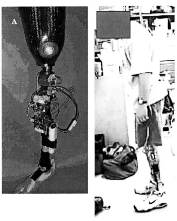
The MIT knee itself (see figure two) is
mechanically passive. It generates no energy and can
only resist applied torques (this is true of all knees
currently available). The basic knee design is a
series of interspaced blades which slide past each
provides a varying magnetic field perpendicular to the
plain of the blades. This field pushes the blades
together and makes it harder to slide past one
another. The knee is also filled with a magnetic
particle fluid. The field lines up the particles of
the fluid into chains and thus changes the shear
resistance of the fluid. The result of this design is
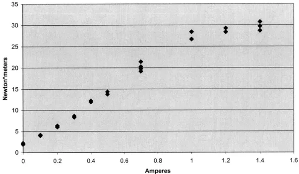
that the knee will provide a resistive torque as a
function of current applied to the electromagnet (see
figure three).
~tIs
Figure 2- The M.I.T. Knee hold the leg stump and on and foot)
(connected on the top to a socket to the bottom to an artificial leg, ankle,
1.- -4 ,
M.I.T. Knee resistive torque output as a function of commanded current 35 30 25 $ 20 E 0 1j 15-0 z 10 01 0 0.2 0.4 0.6 0.8 1 1.2 1.4 Amperes
Figure 3- Knee resistive torque as a function of commanded
current. Several data points were taken at each current to check
repeatability.
The knee has a built in rubber "knee-cap". Its
purpose is to dampen somewhat the noise and vibrations
when the knee extends rapidly to a completely straight
configuration.
There are three input signals to the knee- knee
angle, bending moment below the knee (either a loaded
toe or loaded heel), and applied axial force to the
knee (force along the axis of the leg). The
derivative of knee angle is also taken to give angular
velocity. The electronic controller of the knee
consists of a microprocessor, memory units, analog to
digital converters for the sensor, and a current
Chapter 4- The Controller
Conventional Prostheses
Any conventional knee prosthesis has four major
goals corresponding to four of the five phases of gait
(there is no requirement for stance-extension since
conventional prostheses do not allow the knee to flex
and extend during stance). During early stance it
must provide stability (i.e. prevent knee buckling).
During pre-swing, the knee must go easily into
flexion. During swing-flexion, the maximum heel-rise
must be limited. Finally, during swing extension,
there must be sufficient deceleration for a soft stop
while still ensuring the knee reaches full extension.
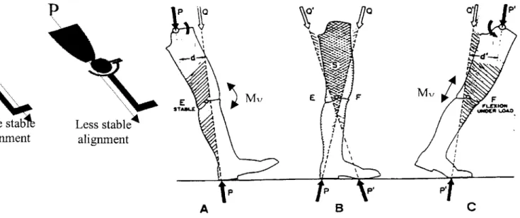
For conventional prostheses, the first two goals
are achieved by altering the static alignment of the
subject's weight line relative to the axis of rotation
of the knee (see figure four). If the weight line is
anterior to the knee, the knee is said to be stable
(that is, it will not buckle). If the weight line is
posterior to the center of rotation at heel strike,
the subject must provide an extensive torque about the
subject's ability to stabilize the knee in this
fashion determines, when aligning the knee on the
subject, how far posterior the weight line can be to
p
More stab
alignment
Less stableA
alignment
E STAN"A PA
E F .4 /P N,B
P1 F OFLXXIO14 UOC. LOAO PC
Figure Four- Stability in the alignment of a prosthesis. In A,
the leg is in the position it would be at heel strike (initial
loading) . My is the voluntary hyperextensive moment the subject
can supply to keep the knee from buckling. The weight line, P
causes a flexive torque about the knee causing it to buckle. The
sum of these two torques can be represented by an equivalent
force vector 'Q'. Q must pass in front of the knee axis for the
knee to be stable at heel strike. The magnitude of My determines
how far back, relative to the knee axis, the socket can be
aligned. In C, the leg is in the position it would be in during pre-swing. In this diagram, My is the voluntary flexive torque
that can be supplied by the subject (from his hip muscles). The
weight line, P, will tend to cause a hyperextensive torque about
the knee axis. The equivalent force vector, Q, must be behind
the knee axis for flexion to take place leading to swing. The
diagram on the left shows how the further forward the socket is aligned relative to the knee axis, the more hyperextensive torque
is supplied by the weight line at heel strike. (34)
When attempting to go into pre-swing, there must
be little or no resistive torque to interfere. If the
weight line of the subject at pre-swing falls in front
of the axis of the knee, an extensive torque is
generated which makes pre-swing more difficult. Knee
alignments with the weight line relatively far forward
(sacrificing ease of pre-swing for stability at heel
strike) are referred to as "safe" alignments. Knee - 061 . .
alignments with the weight line relatively far back
(sacrificing stability at heel strike for ease of
pre-swing) are referred to as "triggered" alignments.
To provide flexion and extension resistance
during swing, most prostheses have hydraulic cylinders
of some sort' to aid with swing control (see figure
five). The hydraulics provide a resistive torque
proportional to the velocity of the knee squared. On
some knee units, the damping constant can be set by
the prosthetist. Some units also allow the flexion
and extension damping to be set separately (using
different hydraulic cylinders or a set of hydraulic
one-way valves).
1 There have actually recently been introduced several new varieties of mechanical knees
including those with moveable centers of rotation and "friction locks" to enhance stance stability.
Socket attachment point
Knee axis of rotation
Direction
of knee
flexion
Hydraulic cylinder to
provide resistive torque
Lower leg attachment point
Figure
5-
Conventional knee with hydraulic cylinder
The MIT knee
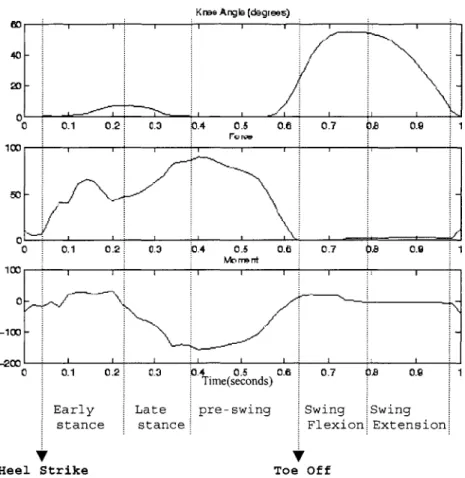
The knee control algorithm takes information from the sensors and from its internal state. It then
determines which phase of gait the walker is in. Based on the phase of gait and the sensor inputs, it
determines the appropriate resistance for the knee. The controller implements a state machine with each state corresponding to a phase of gait (see figure six). State one is stance-flexion (or early-stance), State two is stance-extension (or late
stance), State three is pre-swing, State four is swing-flexion, and State-five is swing-extension.
Stance
The MIT knee is programmed to tell the
difference between initial loading during stance and the beginning of pre-swing. It can therefore provide stance stability without needing to rely solely on static alignment and subject hyper-extensive effort like conventional prostheses. The knee therefore does not have to be aligned such that it will be locked all
the way through stance to ensure safety. Rather, it is designed to allow the controlled flexion and
K re Angle (degrees) 40 0 01020304 0.5 0.6 07 OS 09 01 0 0.1 02 03 b4 0.5 0.6 07 0S 09
1
100 c 1 - ' - - --MW rr t 0/
0 V 0.1 0.2 Early stance Late stance Heel Strike 0.4 0.5 0.6 0.7 Time(seconds) pre-swing Swing Flexion V Toe offFigure 6- Sensor data from the prosthesis for a single stride
showing knee angle (in degrees), Force (in arbitrary units) and
Moment (in arbitrary units) . Heel Strike (when the foot first
hits the ground) and Toe-Off (when the foot leaves the ground for
swing) are marked, as are the five states the controller cycles
through during gait
The first state in the controller corresponds to
early stance. The trigger to enter State one is the
foot making contact with the ground, as measured by
the force sensor. Under normal operation, the knee
will flex while in this state and then switch to State
two (stance extension) when maximum stance-flexion is
reached.
LB 0.9
Swing
Extension
The resistance for early stance is determined as
a linear function of the peak force in the step
before, as well as angle and angular velocity. That
is:
Torque= Beariy-stace* angular velocity*angle
(Where Beariy stance = C*peak axial load from previous step + D)
The logic behind this is that a heavier subject,
or a subject walking more quickly (corresponding to a
higher dynamic ground reaction force) will require
more support from the knee during stance flexion. The
constants in the formula (C and D) were derived
empirically from testing what levels of resistance
were most comfortable for the subjects in the study.
The velocity dependence in the determination of
torque is there primarily so that the torque will be
zero when the knee starts flexing to allow the subject
to initiate bending and zero when it reaches maximum
flexion, thereby allowing the subject to reverse and
enter stance extension.
The angle dependence in the determination of
torque is also there to ensure low torque to allow the
torque as the subject bends, giving the more safe
feeling that it will catch them.
The second state corresponds to extension during
stance. The state begins when stance flexion is
completed and the velocity turns positive2. It ends
when the conditions for pre-swing are met.
The resistance for stance extension is a function
of the angular velocity, specifically:
Torque = Biatestance * angular velocity
The damping constant, Biatestance is fairly low and
was determined empirically from testing for comfort on
the subjects. The only major issue with this state is
preventing noise when the knee re-extends into the
"knee-cap", which is already partially limited by the
rubber bumper (see chapter 3) . Therefore, no
adaptation, per se, is necessary for this state. As
in State one, the primary reason for the velocity
dependence is to assure that at the beginning of the
state (when the knee is maximally flexed) the torque
will be low, allowing the subject to begin extension.
2 In all places in this document, 0 degrees refers to the knee when in is straight. By convention, positive angles refer to the knee in flexion and positive angular velocity refers to a flexing velocity.
The third state is pre-swing. The trigger for
pre-swing presents a relatively difficult problem. At
heel strike, when high torque is needed to prevent
knee collapse, the knee is straight and still with the
subject's weight on the leg (see figure six).
Likewise, at the beginning of pre-swing, the knee is
straight and still with the subject's weight still on
the leg. In pre-swing, however, it is critical to
have no resistive torque to impede the subject's
kicking the leg out into swing phase. Therefore one
is left with two conditions with very similar sensor
signals but requiring diametrically different
responses.
Two different controllers were developed for this
project, one for a two sensor system- angle and force,
and one for a system with three sensors- angle, force,
and bending moment (see chapter 3). A different
solution to this state transition problem was found
for each of these systems.
For the two sensor system, four criteria need to
be met for switching from State two to State three.
a) The knee must be close to straight (within 2
degrees)
zero)
c) The axial force must AT SOME POINT have passed higher than a force threshold
d) At least 300 msec must have elapsed since 'c'
Condition 'a' is present so that the knee can not go into low torque mode when the subject has a bent knee and is relying on it for stability. The angle is not set to zero (perfectly straight) since with stance flexion and extension, it is possible to choose to go into pre-swing before stance-knee-extension is
entirely complete.
Condition 'b' is present so that if the knee IS going through knee flexion and extension, pre-swing will not be triggered before the knee is fully
extended (or as extended as it is going to get) and comes to a stop. Without this requirement, the last two degrees of stance-extension would be in pre-swing at zero torque.
Condition 'c' prevents the knee from going into pre-swing immediately at heel strike. The force
threshold is calibrated during the first ten steps of walking by taking the average peak force per step and
theory, peak force when walking is approximately 120%
of body weight, so the threshold is approximately 60%
of body weight. It takes some time from initial heel
contact to load to this level. Condition 'd' then
gives the subject time to move their weight line
forward. By the end of three hundred milliseconds, a
subject will have already initiated stance flexion if
likely to do so (in which case conditions 'a' and 'b'
prevent the transition to pre-swing).
The knee is also designed to provide stability
when standing, crouching, or sitting. If State one or
State two is entered and the axial force is LESS then
60% of body weight (e.g. they are standing on both
feet) pre-swing will not be entered and stance
stability will be maintained.
For the three sensor system, the switch to state
three is simpler. Three conditions need to be met.
a) The knee must be close to straight (within 2
degrees)
b) The knee must be still (angular velocity of
zero)
toe-load above a certain threshold.
Looking carefully at figure six one observes that
stance begins with heel strike (a heel load) and ends
with the weight loading the toe. The threshold for
condition 'c' is determined during the first ten steps
by taking the average peak toe load per step and
multiplying by 80%. In the case of standing still,
crouching, or sitting, the load should be roughly
equally balanced between heel and toe so condition 'c'
is not satisfied and stance stability is maintained.
Swing
The swing portion of gait is speed adaptive in
two senses. In the immediate sense, resistance from
the knee (in most of swing) is proportional to the
angular velocity (as is the case with hydraulic
knees). Angular velocity dependence is beneficial
because a faster moving knee has more kinetic energy
and requires more resistive torque to slow it.
At a higher level, the damping parameters for
swing are determined separately for each walking
3 Throughout this work, a toe moment (the moment caused by loading the toe) is given a negative sign and a heel moment (the moment caused by loading the heel) is given a positive sign.
Therefore, a large toe moment (as required for the transition from late stance to pre-swing) will be a large negative value.
speed. This is an advantage over mechanical units
whose damping level can only be set to one value (and
will therefore perform well only over the range of
walking velocities for which it was optimized).
There are several possible methods of
approximating walking speed. Obviously, the optimal
method would be to directly measure the linear speed
of the person walking, such as by using an
accelerometer and differentiating. Unfortunately the
noise inherent in such a system makes it impractical.
Another fairly direct method is to measure the
stride time. Shorter stride times will result in
faster gait speeds. The major disadvantage of this
method is that the information on walking speed is
always at least one step old (one must complete a
stride before the stride time is known and one can
only apply that information to the next step).
One method for approximating the subject's
walking speed before swing phase begins is to look at
the peak axial force during stance. It is logical to
assume that as walking speed increases, the dynamic
component of the vertical reaction force will increase
as well (for example, it can reach two or three times
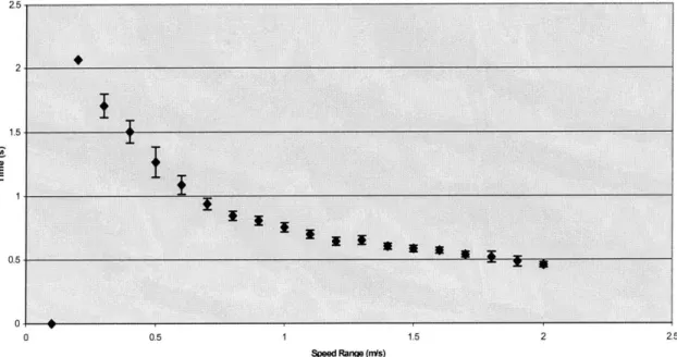
Another possibility for approximating walking
speed is to look at the contact time for the stance
phase preceding a given swing phase. Biological data
(see chapter 6) shows a strong inverse correlation
between contact time (time from heel strike to toe
off) and walking speed (see figure seven).
All Normal Subjects: Contact Time
2.5
1.
C
4-0 0.5 1 1.5 2 2.5
Speed Range (nis)
Figure 7- Contact time (from heel strike to toe off) vs. walking
speed for a pool of unimpaired subjects
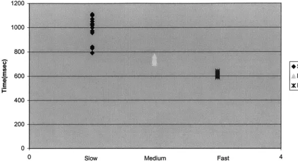
To test for the best possible discrimination
between speeds, a subject was asked to walk fast,
medium, and slow. For several steps at each speed,
the maximum stance axial force and stance contact time
were recorded. The results can be seen in figure
distinction between the three walking speeds using
contact time then using axial force.
Another basic premise for swing is that the
resistance should be applied as late as possible in
the swing. This is based both on mimicking biological
behavior and for safety reasons.
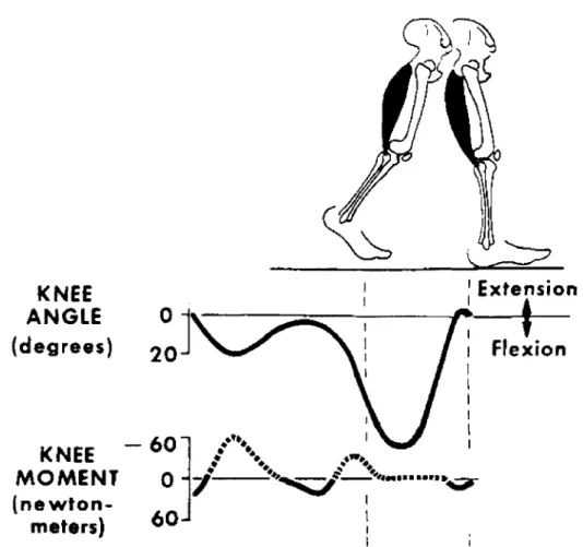
The fact that biologically, muscle moment is
generally applied only at the beginning and end of
swing phase can be seen from figure nine. From a more
practical standpoint, both consultation with
professional prosthetists (20) and our own experience
shows that torque applied too early leads to at least
subject discomfort and at worst tripping.
The fourth state is swing flexion. It begins
when the axial force sensor determines that the foot
is on the ground and ends when the knee reaches its
Contact Time- Heel Strike to Toe Off 1200-1000 800 * Slow E60 A Medium E Fast 400 200 0
0 Slow Medium Fast 4
Maximum Axial Force (arbitrary units)
160 140 120 100 +Slow 80- Medium X Fast 60 40 20 0
0 Slow Medium Fast 4
Figure 8- Two methods of estimating walking speed. Both the
axial force of the leg and the contact time are correlated with
speed. There is less overlap and therefore more accurate detection using contact time.
KNEE
Extension
ANGLE
01
(degrees)
2 0Flexion
-60~
KNEE
MOMENT
0-
(newton-meters)
-Figure 9- Knee moment in biological walking shows that most work
in swing is done at the end of swing flexion. From (31)
Knee resistance for swing flexion is a function of angle and velocity. There is no torque at all
until the knee flexes past 15 degrees. After that, it is determined by:
Torque = Bswingtiexion*angular velocity* (angle-15)
The dependence on angular velocity, as previously mentioned, is useful because within a given step,
faster then expected for a given walking speed will
require more damping to slow it in time.
The angle dependence prevents resistive torque
from being applied too early, as previously discussed.
The form of the function also prevents torque from
being applied too suddenly (which the subject could
feel as a jarring sensation). Specifically, the
maximum possible damping value ramps as a linear
function of flexion angle, starting at fifteen
degrees.
The auto-adaptation for State 4 is designed to
limit the maximum flexion angle for swing. The peak
flexion angle (and as a consequence the maximum heel
rise) during swing is very important in amputee gait.
If it is too high, the prosthesis will take too long
to complete the swing cycle and will not be extended
and ready for the next heel strike. To prevent
tripping in this way, amputees are forced to either
walk slower or work harder to push the knee forward
during swing extension.
If, on the other hand, the heel does not reach a
sufficient angle, there is an increased chance that
4 For some walkers, the knee flexes past 15 degrees while the leg is still on the ground (i.e. the
controller is still in State 3- pre-swing). In this case, torque is still applied in pre-swing as though it is in State 4.
the amputee will stub their toe on the ground when
swinging it forward (because flexing the knee in swing
has the effect of "shortening" the leg to assure toe
clearance with the ground).
Finally, a large difference in maximum flexion
between an amputee's biological leg and the prosthesis
is clearly visible and does not lend itself to dynamic
cosmesis.
Adaptation for State 4 is designed so as to, if
possible, keep the maximum knee flexion between sixty
and seventy degrees. It should be noted that this is
slightly arbitrary. Different works of literature
suggest anywhere from 50 to 70 degrees as being
reasonable for unimpaired adult walkers. The upper
end of the range was chosen because
a) It is safer to have slightly too much flexion
then to risk applying too much resistive
torque.
b) As discussed in Chapter 6, different studies
using different methods for determining
angles are difficult to compare.
The adaptation algorithm, therefore, checks for
greater then seventy degrees, the constant Bstance_flexion
is increased by an amount proportional to the amount
by which it is greater.
If, after a few steps, the maximum flexion angle
in swing is always below sixty degrees, the constant
Bstance flexion is decreased. It is important to remember
that since the knee can only supply resistive torques,
nothing can be done for a subject whose maximum
flexion angle is less then 60 degrees even when
Bstance_flexion is zero.
Since the controller is speed adaptive, a
different value for Bstance_flexion is stored for each
walking speed range (as approximated by contact time).
These values are stored in an array and the correct
one chosen for any given step.
The fifth state is swing extension. It begins
when the knee reaches maximum flexion in swing and
begins to extend. It ends at heel strike at the
beginning of the next stride.
The primary goals are to dampen swing
sufficiently such that terminal impact (the impact
when the knee reaches 0 degrees and is mechanically
forced to stop) is not too hard (the knee is not
too much energy out of the swing such that the subject
has to use excessive energy to extend the leg in time
for heel strike.
Knee resistance is a function of angle and
velocity, being turned on for only the last few
degrees of extension. The torque is governed by the
equations:
Torque 0 for knee angle > X
Torque = Bwingextension*angular velocity for knee angle < X
Adaptation for swing flexion is based on the
concept of using enough deceleration to decrease
terminal impact while ensuring that the knee always
reaches full extension before heel strike. The angle
X at which the damping turns on starts at zero and
increases until there is a step in which swing does
not quite reach full extension. At that point, the
angle X stops rising.
Experimentation over the course of this study has
shown that it is absolutely critical that the leg
always reach full extension. If it doesn't, even by a
small amount, most subjects will be extremely
Therefore, once a single step has not made it to
full extension, X will not increase again unless 20
steps do make it to full extension. It only requires
a single step not reaching full extension, however, to
cause X to decrease. The result is an adaptation
biased towards lower torque for safety.
The algorithm as described so far has a problem.
The more powerful walkers in the subject pool would,
in a desire to never let the knee not reach full
extension, put more and more energy in from the hip as
X increased. There result was that X would continue
increasing far past the point where they could walk
without quickly fatiguing. Therefore, as an
additional safety precaution, there is an empirically
determined maximum value for X. It was determined by
measuring the highest value that allowed for
comfortable walking in the most "sensitive" member of
our subject pool.
Bswingextension is held constant at a fairly high value. The decision to modulate the angle range where
the knee is slowed rather than the level of the torque
(which is high when it is on at all) is consistent
with the principle of using torque only as late in
As in State 4, the controller is speed adaptive.
Therefore, a different value for X is stored for each
walking speed range. These values are stored in an
Chapter 5- Extra modes of walking and features
STAIRS
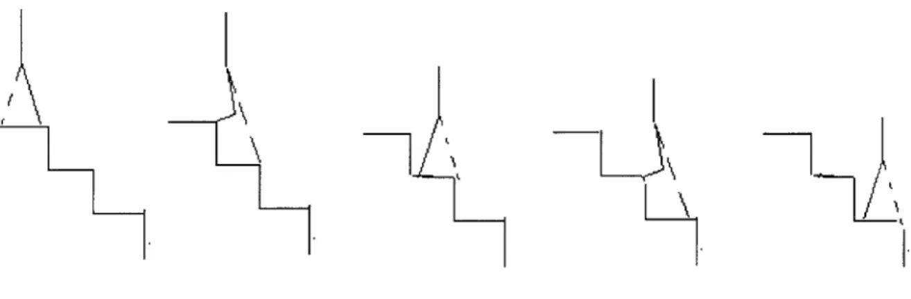
Amputees use several strategies for walking down
stairs. The easiest method is to lower oneself down
to the next step using the biological leg. The
prosthetic leg is then brought down to the second step
and the process repeated for the third step (see
figure 10). The stairs are therefore descended one
step at a time.
Figure 10- Descending stairs one at a time. The prosthesis (the
dashed leg) never has to support weight when bent.
Another method for more aggressive amputees is
known as "jack-knifing". First the prosthetic leg is
lowered to step 2 using the biological leg. Then,
rather then bringing the biological leg down to the
second step, it is lowered directly to the third (see
Figure 11- Descending stairs "step over step". The prosthesis (the dashed leg) has to support weight when bent.
This requires the subject to bear his full weight
on the prosthesis. Since conventional prostheses
provide little to no stance torque, this means the
knee collapses under the weight. By using excellent
timing, an amputee can manage to have their biological
leg in place on the third step in time to catch him.
The descent however, in addition to being difficult,
is noticeably asymmetric.
The MIT knee allows for stance support during
stair descent. The difficulty (similar to that in the
State 1 to State 3 transition) is that bending the leg
to go down stairs looks very similar (to the
controller) to the actions leading to pre-swing in
leg is straight and still with the subject's full
weight on it just before it begins to flex for
pre-swing. The same is true for flexion to lower the body
to the next stair. In the case of pre-swing, as
previously mentioned, it is critical to have no
torque. In the case of stair descent however, a high
level of torque is needed.
The two and three sensor systems handle the
state transition problem differently. For the two
sensor system, the key is condition 'd' in the
requirements for transition from stance to pre-swing.
Experiments in this study show that almost without
exception, walking down stairs is fast enough that the
knee begins flexing before 300 msec have elapsed from
the time the knee is loaded. Once the knee is bent
past two degrees, condition 'a' keeps it from
transitioning to pre-swing. The leg then will leave
the step and go into swing phase.
In the event that the system does transition
to pre-swing during stair descent, there is a method
(using the two-sensor system) to detect the mistake.
When entering pre-swing, the force drops off rapidly
as the foot leaves the floor for swing. When, on the
body down steps, the force falls off more slowly (see
figure twelve). Therefore, if the force does not fall
off with a certain slope (measured with respect to angle bent in this case), the state machine goes back
into State one.
Axial Force unloading during knee flexion at the end of stance-- Stairs vs slow and fast walking 160 140 120 100*Force(Fast,Walking) 80 MForce(Stairs) Force(Slow Walking) 60 -IA. 40-20 0 0 5 10 15 20 25 30 35 Angle(Degrees)
Figure 12- Axial Force unloading during knee flexion at the end of stance-Stairs vs. slow and fast walking. Note that the force for stairs falls of significantly slower as the knee bends during stair descent then for either slow or fast walking
In the three sensor system, a large toe moment is one of the triggers to go to pre-swing. In stair
descent, the subjects are instructed to place their
foot with the heel on the step and the toe hanging
over it. Therefore the toe moment is not present and
In case the system accidentally goes into
pre-swing, it will go back if a heel moment is detected
while the leg is still close to straight (when the leg
is bent in pre-swing, it means the foot is being
unloaded and the moment is no longer a reliable signal
(see figure 6)).
The three-sensor system is more robust in terms
of state detection for stair descent. The trade off
is the additional cost (and/or) weight of another
sensor and the added possibility of malfunction should
the sensor break.
"Pathological" state transitions
In addition to the normal sequence through the
states, there are several abnormal (or pathological)
sequences to cover unusual situations, hesitations,
and stumbles. The details are:
1. State 1 (early stance) can transition to State 3
(pre-swing) without going through State 2 (late
stance). This is because many subjects do not
make use of the stance-flexion/stance-extension
capability of the knee (see Chapter 6) and
conditions for transition from State 1 to State
3 are the same as those from State 2 to State 3.
See figure 13 for an example of the signals
resulting from a subject going through the
normal gait cycle (as in figures one and six)
but without flexing the leg in stance.
2. State 1 and State 2 can transition directly to
State 4 (swing flexion). This is for situations
where, for whatever reason (as, for example in
stair descent) where the foot leaves the ground
without first going through the pre-swing state.
The trigger is simply the foot leaving the
ground.
3. State 2 can transition back to State 1 if the
leg begins to flex again while still on the
ground and the conditions for pre-swing are not
met.
4. In swing, if the leg reaches full extension
before heel strike, it is held in full extension
until heel strike takes place. In case the leg
is on the ground and has not been detected
because of sensor noise, this "holding torque"
is programmed to have a velocity dependence the
5. If the system has been in pre-swing for several
seconds, it will transition back to State 1.
6. In the case of a stumble (i.e. the foot hitting
the ground in the middle of swing phase), one of
two things should happen. If the controller is
in State 4, there is a path directly to State 1
if weight is placed on the foot. If the
controller is in State 5, the normal transition
to State 1 occurs whenever weight is placed on
the foot. In either case, there is stance
Knee Angbg (degrees) 60 C 0.1 0.2 0.3 0.4 0.5 0.6 0.7 0B 0.9 1 50 - 0-S 0.1 0.2: 0.3 0.4 0.$ O.C 0.7: 01B 0.9 WMornt itt II I I 0 -10 _Om nI --- C. V 0.1 0.2 Early stance Heel Strike 0.3 0.4 0.5 Time(seconds) pre-swing 0.6 0.7 Swing Flexion Os 0.d Swing Extension Toe Off
Figure 13- Sensor data from the prosthesis for a single stride
showing knee angle (in degrees), Force (in arbitrary units) and
Moment (in arbitrary units). For this stride the subject did not
flex the knee during stance.
Overviews of both the two sensor and three sensor
state machine rules can be seen in figure 14.
Non-zero axial force
State 1
Stance Flexion
-Nonzero a force -Axial fo has been I threshhold some tin -Knee is s and alm straiehState 3
Knee Break
N x rc ti )s t-Derivative of force with respect to a or time not steep enough for walkin
OR
-Time too long for preswing INonzero axial force 4
Knee extending Nonzero axial force
-Knee Break conditions not met
State
2
-Knee flexing -
.Stance Extension
-Nonzero axial force ial -Knee Break
al conditions not met
st Zero -Axial force has Zero axial force For axial been past
force threshhold for some S-INtime
-Knee is still and
almost straight
State 4 """
Zero axial force
Swing Flexion
ngle ~ -Non-zero axial
g force
-Knee extending
State 5
1-Swing Extension * Knee extending
Figure 14A: A diagram of the finite state machine with states in ovals and
transition conditions in rectangles. A controller using only two sensor
inputs: knee angle and axial force.
PP-Nonzero axial fo
-Knee extending -Nonzero axial force
-Toe moment below threshold
Sta
Stance
-Knee not too flexed -Nonzero axial force -Heel moment above threshold
te I
Flexion
-Knee flexing-Nonzero axial force -Toe moment below
threshhold
-Nonzero axial force Zeo -Nonzero -Toe moment Zxial -Toe n above threshold foc above t
-Knee straight,still -Knee str
State 2
tance Extension
axial force
moment Zero axial force hreshold
aight, still
State 3
ZeroState 4
Pre-swing
Swing Flexion
State 5
-Knee extending,Swing
Extension/
-zero axial forceFigure 14B: A diagram of the finite state machine with states in ovals and
transition conditions in rectangles. A controller using three sensor inputs:
knee angle, axial force, and the bending moment below the knee.
Autocalibration
In addition to the adaptation in the individual states, some information about the subject and the sensor calibration is calculated by the knee during
walking. The average peak force and average peak
moment are calculated by recording the peak moment for
the first ten steps of normal walking when the system
is powered up. Nonzero axial force]
The angle sensor is also periodically
auto-calibrated. Every 10 steps the minimum angle reached
is checked. If it is not zero, the offsets on the
sensor are adjusted.
Power Saving
In order to increase the life of the battery, the
electromagnet is shut down completely when
unnecessary. Specifically, if the velocity sensor
reports that the knee has not moved for three seconds,
the electromagnet is shut off, regardless of what the
state machine says it should be doing. Movement
immediately reactivates the torque.
Chapter 6- Analysis
It should be noted at the outset that the goal of
this project was not primarily to develop a knee which
would allow "better" level ground walking, which is
very difficult to define (see chapter 2). Rather, it
was to develop a robust control system for an
electronic knee which was auto-adaptive, speed
adaptive, and allowed for stable stance flexion and
The knee was tested on five experienced above the
knee amputees. Table one shows the distribution of
the subjects' heights, genders, and conventional
prostheses.
Table 1: Information about subjects
Subject Gender Height Conventional
Code Prosthesis
CPL M 6'-1" Endolite ESK
CLH F 5'-4" Otto Bock
3R60
RWE M 6' Otto Bock
intelligent prosthesis
JBR M 6'-2" Tae Len
LAC F 5'-5" Endolite ESK
The first test, and the most important one, was
almost entirely qualitative. The subjects had to be
able to walk both successfully and comfortably. When
descending stairs, the knee had to provide sufficient
support and when walking up or down ramps the knee had
to continue to function normally. With the exception
of a few minor problems mentioned in chapter seven,
the knee passed these qualitative tests.
Most quantitative testing was done at Spaulding
collection was done with a Vicon analysis system. The
system uses reflective markers placed at
pre-determined anatomical locations. Based on anatomical
assumptions and measurements made on the subject,
joint angles and velocities are estimated. Kinematic
analysis was done with the use of infrared cameras
which record light reflected off the markers. Two
force plates on the walkway record forces and moments
during the one or two strides when the subject is in
range of the camera.
The marker placement system is discussed by
Kadaba(24). As is discussed in detail in that work,
different placement systems and analysis routines for
the kinematic data will lead to different results for
measured joint angles. It is therefore, for example,
of no use to compare the maximum knee flexion as
measured by the Vicon system to the desired sixty to
seventy degree range in the knee algorithm. The knee
code is adapting so that the peak angle as measured by
the potentiometer on the knee will be in the target range. The readings from the reflective marker system
at the Gait Lab are not directly comparable (although
Likewise, the data from the prosthesis cannot be
compared literally to published biological norms
(unless they were taken using the exact same system).
Therefore, the first data analyzed for this study was
from 12 healthy, unimpaired adults. Each subject was
told to walk at self selected "normal", "fast", and
"slow" speeds.
Each of the amputee subjects was then tested
twice. For the first test they used their
"conventional" prosthesis (as listed in table one).
For the second test they walked using the MIT knee.
For each of the tests, like the unimpaired subjects,
they walked at three self selected speeds- "normal",
"fast", and "slow". For each speed the subject took
enough steps such that there were around ten good
recordings for both the prosthetic leg and the
biological leg.
Among the data recorded on each subject was the
walking speed, the peak swing flexion angle, and the
time for swing flexion and extension. The data was
analyzed so that the subjects' conventional prosthesis
and the behavior to the MIT knee could be compared
symmetry is very important) and against the range of
biological behavior for adults without prostheses.
Data on stair descent was also taken using video
at 30 frames per second. The quantitative value being
judged was symmetry in time between the sound side and
the prosthesis.
Prosthesis induced pathologies
In judging a prosthesis it is critical to
remember that there is a human in the system. The MIT
knee is designed to adapt its parameters to meet the
needs of individual subjects. Subjects, however, will
also adapt to compensate for the behavior of the
prosthesis they are using.
There are certain common habits that long-time
amputees tend to pick up to compensate for
deficiencies in the prosthesis. According to a study
done by James(29), a normal walker will spend 61% of a
walking cycle in stance. An amputee, on the other
hand, will spend only 57% of a walking cycle in stance
when weighting his prosthesis, but 65% when weighting
his natural leg. This is presumably to some degree
due to discomfort in putting weight on the prosthesis.
walking speed will walk 0.96 meters per second as
opposed to an unimpaired walker who will go
approximately 1.5 meters per second under the same
conditions. Prosthesis swing is also slower then the
swing of a natural leg. Whether this is because the
leg reaches a higher maximum flexion angle in swing is
unclear.
Another habit many amputees pick up is raising
themselves up on their good leg while going over it.
Generally, this is because of a fear that the
prosthesis, when swinging through, will not clear the
ground. Likewise, an amputee will often circumduct
(swing the leg around outward) with the prosthesis to
make ground clearance more likely.
Most complicating for the purposes of study is
the way amputees are trained to pull themselves over
the leg (apply a hyperextensive torque) at heel
strike. Since most prostheses will not support stance
flexion, amputees are trained that any bending of the
leg during initial loading is an indication that the
knee is about to buckle and drop them.
It is therefore very difficult to convince
subjects to allow the knee to flex at heel strike,
the knee will not buckle and drop them. In biological
walking, the knee flexes in stance to somewhere on the
order of 20 degrees (depending on walking speed).
Only two of the five subjects in this study allowed
any stance flexion at all, and only one of them
allowed stance flexion above a couple of degrees (that
subject's data is shown in figure 6). Aeyels
experienced similar difficulties in his studies of
Chapter 7- Results and Conclusions
Qualitatively, the knee seems quite successful
with the exception of the smoothness of stance flexion
(see Appendix A). The stance flexion function was
very exciting for the one subject who managed to take
advantage of it.
The next test was to check the adaptation
routines. An example of swing flexion as a subject
walks at a single speed is shown in figure fourteen.
Note that the damping fact, Bswing-fiexion (see Chapter 4),
stays at zero for the first several steps while the
sensors auto-calibrate themselves. During this time,
heel rise is excessively high (the target being
between sixty and seventy degrees)5 . Then, as the
adaptation begins, it quickly reaches and maintains a
value which puts the maximum swing flexion angle in
the target range.
s Note that the angle measurements in figure 14 were measured by the knee's angle sensor, not kinematic measurement system at Spaulding rehab hospital. It is the only set of angles so measured in this chapter (see chapter 5 for details on angle measurements).
Swing-Flexion Adaptation 90 100 80 70 .80-7070 60 60 50
* Maximum angle in swing-flexion
.E . Swing-flexion damping aC 40 - E 40 30 30 20 1 3 5 7 9 11 13 15 17
Number of steps taken
Figure 14- Adaptation of swing-flexion damping and the resultant
maximum knee-angle as a function of steps taken at a given speed
(the target of the adaptation is to keep the maximum knee angle between sixty and seventy degrees)
On stairs, the descent appears much more
symmetric then the traditional stair-over-stair "jackknife" descent (see chapter 5). For a
quantitative analysis, a subject (the best stair
walker) practiced walking on both her normal
prosthesis and the MIT knee. A videotape (30
frames/sec) was then taken of her descending a flight of stairs in each. For each step, the time from heel-strike to maximum flexion of the knee was calculated.
For her conventional prosthesis, this time, on
her biological leg. Wi
the prosthesis was, on
for her biological leg.
th the MIT knee, the time for
average, only 8% longer than
As previously mentioned, the subjects at the
Spaulding gait lab were asked to walk at a normal pace
as well as a fast and a slow one. Figures fifteen