Publisher’s version / Version de l'éditeur:
Arctic Technology Conference, 2016-10-24
READ THESE TERMS AND CONDITIONS CAREFULLY BEFORE USING THIS WEBSITE.
https://nrc-publications.canada.ca/eng/copyright
Vous avez des questions? Nous pouvons vous aider. Pour communiquer directement avec un auteur, consultez la première page de la revue dans laquelle son article a été publié afin de trouver ses coordonnées. Si vous n’arrivez pas à les repérer, communiquez avec nous à PublicationsArchive-ArchivesPublications@nrc-cnrc.gc.ca.
Questions? Contact the NRC Publications Archive team at
PublicationsArchive-ArchivesPublications@nrc-cnrc.gc.ca. If you wish to email the authors directly, please see the first page of the publication for their contact information.
Archives des publications du CNRC
This publication could be one of several versions: author’s original, accepted manuscript or the publisher’s version. / La version de cette publication peut être l’une des suivantes : la version prépublication de l’auteur, la version acceptée du manuscrit ou la version de l’éditeur.
For the publisher’s version, please access the DOI link below./ Pour consulter la version de l’éditeur, utilisez le lien DOI ci-dessous.
https://doi.org/10.4043/27398-MS
Access and use of this website and the material on it are subject to the Terms and Conditions set forth at
A numerical study of interaction between ice particles and complex ship structures
Seo, Dong Cheol; Pallard, Robert
https://publications-cnrc.canada.ca/fra/droits
L’accès à ce site Web et l’utilisation de son contenu sont assujettis aux conditions présentées dans le site
LISEZ CES CONDITIONS ATTENTIVEMENT AVANT D’UTILISER CE SITE WEB.
NRC Publications Record / Notice d'Archives des publications de CNRC:
https://nrc-publications.canada.ca/eng/view/object/?id=eb9a6fa7-510c-4506-a1da-173a2dc2e8f0 https://publications-cnrc.canada.ca/fra/voir/objet/?id=eb9a6fa7-510c-4506-a1da-173a2dc2e8f0
OTC 27398
A Numerical Study of Interaction between Ice Particles and Complex Ship
Structures
Dong Cheol Seo, and Robert Pallard, National Research Council Canada
Copyright 2016, Offshore Technology Conference
This paper was prepared for presentation at the Arctic Technology Conference held in St. John’s, Newfoundland and Labrador, 24-26 October 2016.
This paper was selected for presentation by an ATC program committee following review of information contained in an abstract submitted by the author(s). Contents of the paper have not been reviewed by the Offshore Technology Conference and are subject to correction by the author(s). The material does not necessarily reflect any position of the Offshore Technology Conference, its officers, or members. Electronic reproduction, distribution, or storage of any part of this paper without the written consent of the Offshore Technology Conference is prohibited. Permission to reproduce in print is restricted to an abstract of not more than 300 words; illustrations may not be copied. The abstract must contain conspicuous acknowledgment of OTC copyright.
Abstract
This paper describes a numerical method of ship-ice interaction. Identifying an operational risk to an ice breaking vessel such as serious interference or sudden efficiency reduction by ice is necessary at early design stage. CFD-DEM coupled approach can be used for this prediction. Combining two numerical approaches, free floating ice particles can interact with the surrounding fluid as well as the rigid hull surface effectively. Ship-ice interaction becomes more complicated around the stern area considering the swirling flow of the propulsion device and the complex hull appendages. Using CFD-DEM method, simulation of ship-ice interaction during the astern operation was carried out. To evaluate the simulation performance, three example cases were conducted. The first and second case is the astern operation with/without the propeller action. For reducing the computational load, a virtual disc model for the propeller action is selected. Then, a simple sensitivity analysis on the ice friction coefficient was carried out to verify if the friction model is working appropriately. CFD-DEM simulation provides a promising result showing a similar ice jamming and pileup pattern with the physical model test. The suggested method can help to understand the ice movement effectively including the hydrodynamic force and the contact dynamics together.
Introduction
When designing an ice breaking vessel, one of the most challenging steps is to predict the ship-ice interaction effectively. This task should be repeated whenever there is a signification design change. Generally, physical model scale experiments, carried out using an ice-tank for the various ice related issues, is the preferred method for assessing the quality of a design.
While various numerical approaches have been suggested for solving the ship-ice interaction problem; there is no distinct solution at this moment. In order to estimate the huge impact load of iceberg collision, a crushable form of ice based on the Arbitrary Lagrangian Eulerian (ALE) model was tested (Gagnon 2012). The main objective of the ALE approach is to simulate the structural deformation of the ship during the ice collision. The ALE formulation requires a huge computational cost which makes the ALE approach inappropriate for the repetitive analysis needed during the early design phase.
Besides the Finite Element Model (FEM) based approach, Discrete Element Method (DEM) is suggested considering its effectiveness when dealing with the massive contact dynamics. DEM has been applied to predict the ice breaking performance such as ice resistance and maneuvering loads (Lau 2011 and Shunying 2013). In order to create a more robust model, an in-depth study of the relevant ice modeling parameters such as friction and restitution coefficient is also carried out (Morgan 2015). Recently, CFD-DEM coupled method has been suggested to achieve realistic ship-ice interaction simulation with increased computing power. Kim et al (2015) and Vroegrijk (2012&2015) conducted level ice simulation and obtained a promising result. Compared with the traditional DEM, CFD-DEM coupled method can take account of the hydrodynamic effect more appropriately extending the simple hydrodynamic model of traditional DEM that uses buoyancy and constant added mass.
The research objective of this paper is to apply CFD-DEM method to simulate the astern operation considering a more serious ice contact. This study focuses on identifying the interference and blockage effect between ice pieces and hull structures which may cause significant decrease in efficiency. Also, a hexahedral composite particle is proposed replacing a conventional spherical DEM particle, which is widely used in the previous studies (Kim 2015 and Vroegrijk 2015). A hexahedral ice piece can allow a more realistic contact and ice build-up pattern such as jamming in small gap. The suggested approach can provide a cost effective way to predict ship-ice interaction at early design stage.
Simulation Scenario
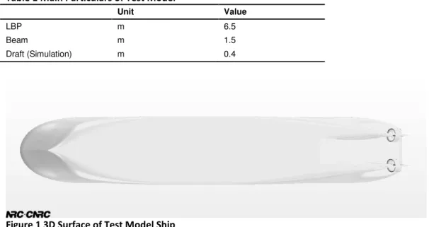
To investigate a more dynamic ice contact with the hull structure, astern motion is selected for the target simulation condition. Generally, ice tank tests are carried out to estimate ice resistance and maneuvering performance in forward operation. However, when encountering a serious ice condition, the ice breaking vessel needs to back and ram again, so efficient astern operation is necessary for independent navigation (Riska). While astern performance may not be important as ahead performance, it needs to be confirmed in the design phase. In this paper, astern performance simulation was conducted using CFD-DEM method. For the simulation, a generic hull with twin propellers was selected in this study to represent a typical ice breaking vessel (Lee 2008). The main particulars of the test model are summarized in Table 1 and the submerged hull surface is shown in Figure 1.
Table 1 Main Particulars of Test Model
Unit Value
LBP m 6.5
Beam m 1.5
Draft (Simulation) m 0.4
Figure 1 3D Surface of Test Model Ship
Numerical Model
General Procedure
All simulation in this paper was carried out using a commercial software package, Star-CCM+. The theoretical backgrounds and detailed formulations of DEM are not dealt with in this paper. A more detail description about DEM method for ship-ice interaction can be found in the reference (Lau 2011 and Shunying 2013). A general analysis procedure consists of two steps. The first step is a preliminary simulation to achieve the hydrodynamic steady-state condition when satisfying the target astern speed and propeller RPM; this step is the same as generic CFD analysis for the resistance and propulsion. The second step is actual CFD-DEM coupling; multiple ice pieces are injected to the steady-state flow obtained in the first step. This simulation carries on for about 10-15 second until a sufficient number of ice particles have passed through the area of interest.
CFD Setup
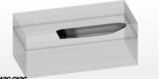
CFD setup is very similar to that used for ship resistance prediction. To reduce the computational cost, a smaller computational domain is created as shown in Figure 2. Because of the low speed when going astern (0.2 m/s) and the proximity of the area of interest around the rudder and propeller, the space between the hull and outlet boundary is reduced. To capture the free surface effectively, a further refinement is done as shown in Figure 2. Also, a fine prismatic layer is attached on the hull surface to take account of the near wall flow as shown in Figure 3. A fine mesh is also generated in the target area between the transom and propeller skeg. The grid size is tuned to meet the wall Y+ value between 10 and 40 as shown in Figure 4. The total cell number of the analyzed case is around 2.6 x 10⁶.
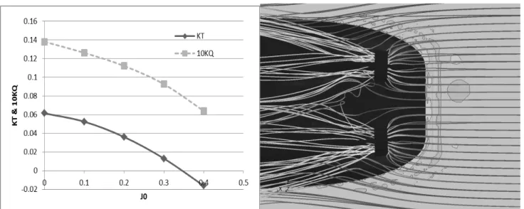
The Reynolds Averaged Navier Stokes Equations (RANSE) are solved using Shear Stress Transport (SST) k-epsilon turbulence model. To capture the free surface effect, the Volume of Fluid (VOF) model is also selected. A virtual disc model is applied to simulate the swirling flow generated by the propeller. Using the virtual propeller model, additional momentum source terms are applied to the cells within a specified disk zone, which produces an equivalent flow pattern based on the given propeller performance curve. For a more accurate simulation including the contact between the propeller blade and ice, a Moving Reference Frame (MRF) method or moving mesh technique is required. When using the virtual disc, an ice particle can freely pass through the propeller blades. However, in this test case, ice piece is assumed to be big enough to prevent a direct contact on the propeller blade. Moreover, using
the virtual propeller model, there is a huge reduction in the computational cost. The propeller characteristic curve used in this study is shown in Figure 5(a). Using the virtual disc, the steady-state streamlines before the ice injection can be obtained as shown in Figure 5(b). Density and dynamic viscosity of water is 999 kg/m3 and 1.6 x 10⁻³ Pa∙sec respectively.
Figure 2 Computational Domains and Generated Grids
Figure 3 Detail Grids around Rudder and Propeller Duct
Figure 5 (a) KT-KQ Curve for Virtual Propeller Model, (b) Stream Line around Virtual Disk before Ice Injection
DEM Setup
In this study, a hexahedral shape of ice particle was created as shown in Figure 6. Compared with a typical spherically shaped DEM particle, the thin block shape of the ice looks similar to the broken/brash ice pieces observed during model tests in astern operation. In this study, 70 spherical particles are agglomerated to form the single piece as shown in Figure 6. The Hertz-Mindlin model is selected for the ship-ice and ice-ice contact. To investigate the effect of the choice of frictional coefficient on the simulation, two different values were examined in this study:
A friction coefficient of 0.3 is suggested for the ice rubble in Morgan (2015);
while a friction coefficient of 0.05 is widely used for the level ice condition based on the work of Timco (2010) and Frederking (2001).
To enhance realistic interaction, two-way coupling is applied. One-way coupling can be used for the typical ice resistance to reduce the computational cost, with the compromise that there is no feedback from DEM particles to the fluid domain such as the flow disturbances and volume fraction changes. The 4 injection points are about 0.5 m in front of the model. The vertical location of the injector is determined by satisfying the hydrostatic equilibrium.
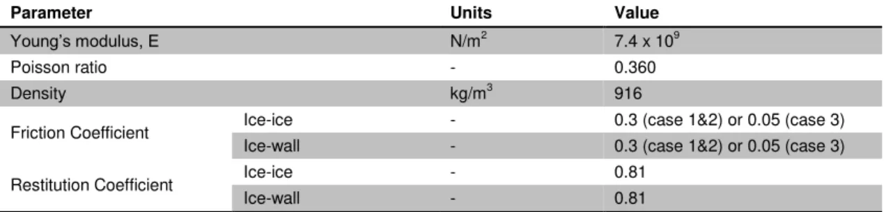
Table 2 DEM Model Parameter
Parameter Units Value
Young’s modulus, E N/m2
7.4 x 10⁹
Poisson ratio - 0.360
Density kg/m3 916
Friction Coefficient Ice-ice - 0.3 (case 1&2) or 0.05 (case 3)
Ice-wall - 0.3 (case 1&2) or 0.05 (case 3)
Restitution Coefficient Ice-ice - 0.81
Ice-wall - 0.81
Simulation Result
In this paper, three test cases were selected to evaluate the simulation performance of the CFD-DEM method, with special attention to the following issues:
if DEM ice particles can be dynamically interacted with the hydrodynamic excitation such as propeller wake;
and, if CFD-DEM method can reflect the different ice friction, which is considered as one of the important experimental parameters in the ice tank test.
The selected simulation cases are summarized in Table 3.
Table 3 Test Case Summary
Propeller RPS Friction Coefficient of Ice
Case 1 0 RPS 0.3
Case 2 13 RPS 0.3
Case 3 13 RPS 0.05
Astern speed (all cases) 0.2 m/s
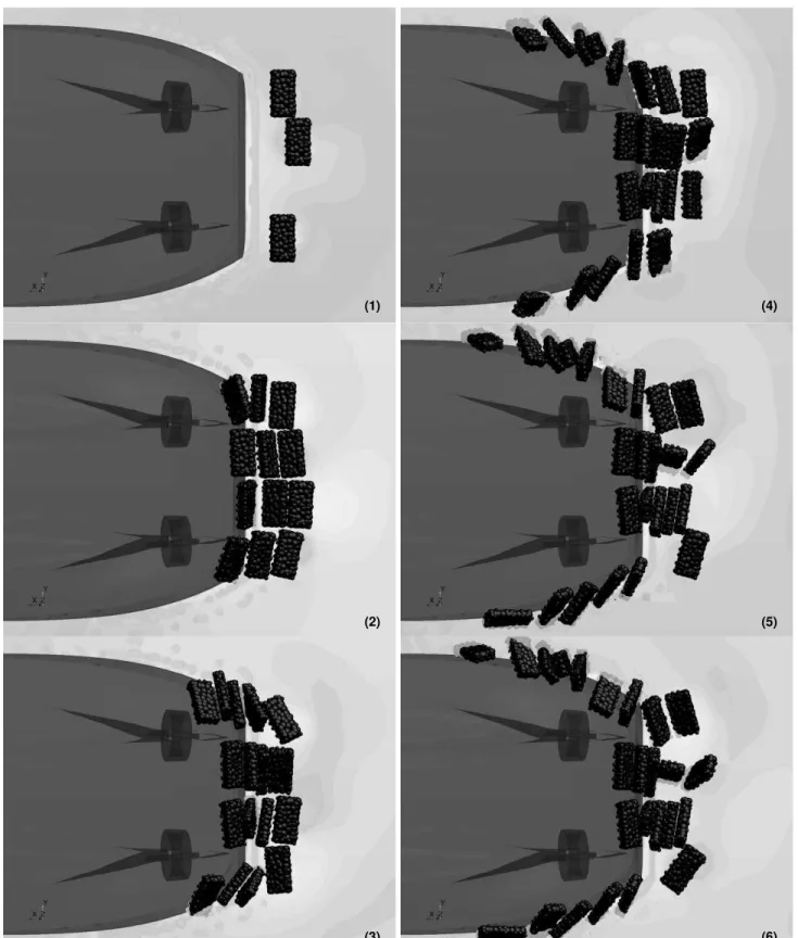
To compare the test cases, the sequential images are captured as shown in Figure 7, 8 and 9. The sequential images can demonstrate the general ice movement. These images are captured at the same time step, usually 1.5 sec interval. The left top image show the initial approach of the ice particles to the ship after particle injection. The second image shows the early contact around the transom. Until this stage, three simulation cases show the very similar behavior. The remaining figures from (3) to (6) show the actual ice behavior and contact pattern under the given condition by changing the propeller action and the friction coefficient.
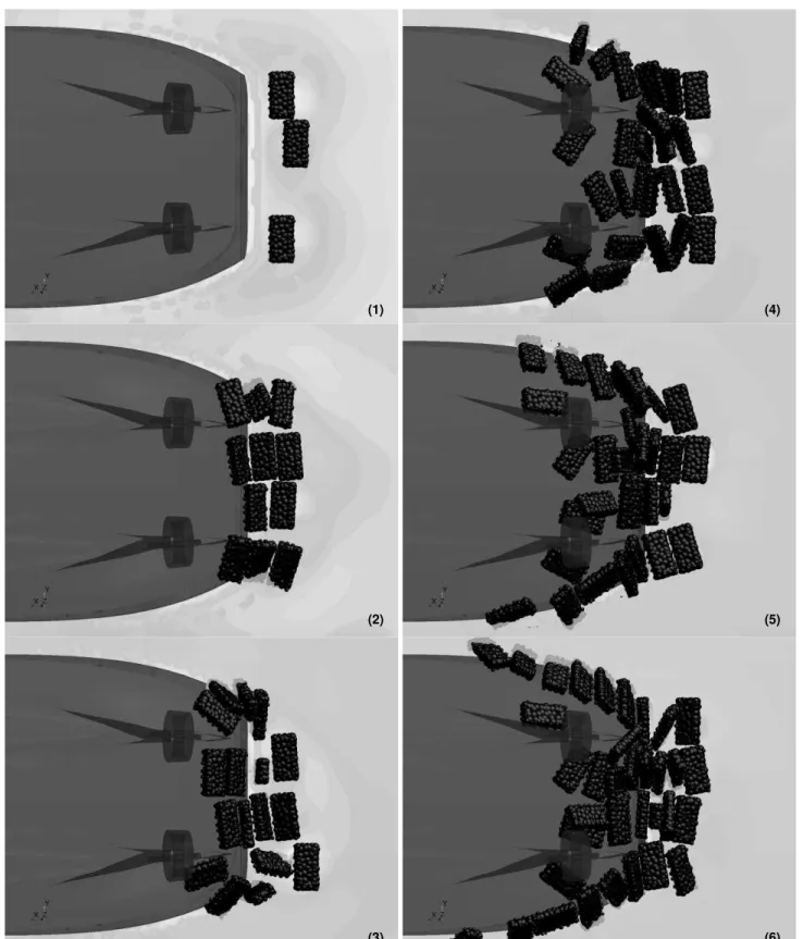
When comparing case 1 and 2, it is observed that the additional hydrodynamic force from the propeller changes the ice particle motion considerably. The outside ice pieces in Figure 8-(3) show a larger rotation toward the propeller. This rotation correlates well with the stream line around the propeller as shown in Figure 5-(b). In Figure 7-(6), ice pileup is observed around the transom area; while, in Figure 8-(6), ice jamming occurs in the flat bottom area between the propellers. It is supposed that the propeller generates strong swirling flow and it pushes the ice piece away. The hydrodynamic effect on the DEM ice particle is taken into account in the simulation. However, the exact hydrodynamic force on the each particle cannot be obtained in the software. For a more precise comparison to validate the hydrodynamic force on the particle, a quantitative evaluation will be required in the future.
Figure 7 Sequential Images of Case 1 (0 RPS and 0.3 of Frictional Coefficient) (1) (2) (3) (4) (5) (6)
Figure 8 Sequential Images of Case 2 (13 RPS and 0.3 of Frictional Coefficient) (1) (2) (3) (4) (5) (6)
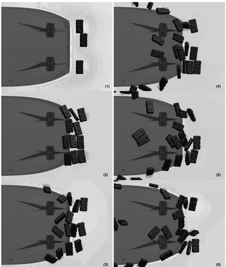
Figure 9 Sequential Images of Case 2 (13 RPS and 0.05 of Frictional Coefficient) (1) (2) (3) (4) (5) (6)
Case 2 and 3 are used to investigate the effect of friction coefficient. In Figure 8-(3) and 9-(3), the lower friction case shows more motion. The ice particles in Figure 9-(3) are moved farther and turned over a little more. Comparing Figure 8-(6) and 9-(6), a more clear discrepancy can be observed. The ice blockage and jamming around the flat bottom and propeller in Figure 8-(6) does not appear in the lower friction case in Figure 9-(6). Considering the continuous contact between the ice particle and the flat bottom area, the ice particle with the low friction can move easily compared with the high friction model. Also, the higher friction can resist the hydrodynamic force and brings the ice pileup in the flat bottom area as shown in Figure 8-(6). In this respect, it appears that CFD-DEM method can capture the effect of different ice friction reasonably well.
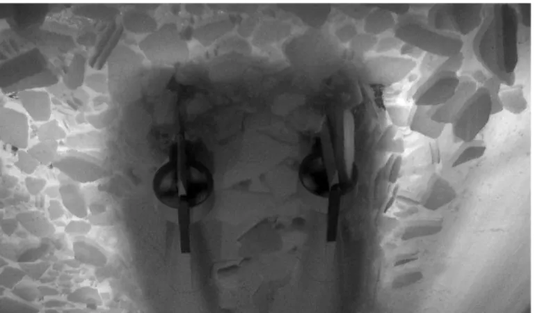
Finally, the simulation result is compared with the experimental result. It is a challenge to control the ice condition such as the number of ice pieces, its size and the approaching direction. So an accurate direct comparison between the physical experiment and the numerical result is impossible. Instead of a precise comparison, a qualitative evaluation is done relying on the representative images as shown in Figure 10. This figure is a typical snap shot of the ice formation during the astern performance test. Compared with the physical model test, the simulation shows similar ice particle positioning around the flat bottom and transom area. A couple of ice pieces strike the propeller duct and turn over; this pattern is also found in the numerical result. However, in Figure 10, the ice pileup location is around the propeller skeg. In Figure 8-(6), this location is around the propeller duct. In Figure 9-(6), there is no specific blockage. So a follow-up study investigating friction coefficient and particle size and shape is required to improve the correlation of the numerical method to the physical test.
Figure 10 Typical Images from Astern Performance Experiment in Ice Tank
Discussion and Conclusion
In order to evaluate the CFD-DEM method for ship-ice interaction, astern performance simulation of a twin-propeller vessel was carried out. To obtain a more realistic ice condition, the hexahedral shape was used in the simulation. The simulation results show that the CFD-DEM method can model the hydrodynamic effect on the ship-ice interaction reasonably. The ice particle can hydro-dynamically interact with the propeller model, and the ice pileup location is affected by the propeller action. By using the virtual disc model, the computational load can be reduced effectively. Also, the friction coefficient is examined to provide a more realistic ice condition. From the comparison study, it is confirmed that CFD-DEM method can reflect the friction coefficient changes properly. The higher friction ice shows more serious ice jamming around the flat bottom area that the lower fiction case. Therefore, CFD-DEM method can be a useful tool to consider the fully-coupled fluid-ship-ice interaction in the design phase. In spite of the promising result, the CFD-DEM method still needs intensive validation. The current simulation results in this study can only provide a qualitative data relying on the visual images. The
imagery may be a very valuable tool for the designer to help assess the effect of shape changes on ice performance when going astern. For a more reliable application, a quantitative evaluation such as the contact force or the particle trajectory should be assessed. In particular, the friction coefficient and the restitution coefficient in the contact model needs to be adjusted to improve correlation to the ice tank test. In the computational aspect, CFD-DEM method is more expensive compared with the typical CFD analysis. To reduce the computational cost, it is necessary to find the optimum simulation setup such as number of DEM particles, shape of the composed piece and the effective domain size.
References
Frederking, R. and Barker, A, “Friction of Sea Ice on Various Construction Materials”, Canadian Hydraulics Centre, Technical Report HYD-TR-67, PERD/CHC 3-49, 2001
Gagnon, R.E, and Wang, J., “Comprehensive Numerical Simulations of a Tanker Collision with a Bergy Bit Incorporating Damage to the Vessel”, 21st IAHR International Symposium on Ice, Dalian, China, June 11 to 15, 2012
Kim, W. J., Kim, S. P., Sim, I. H., Hur, J. W., Kim, H. S., & Ryu, C. H. “Ice Resistance Estimation and Comparison the Results with Model Test.”, International Society of Offshore and Polar Engineers, The Twenty-fifth International Ocean and Polar Engineering Conference, Kona, Hawaii, USA, 21-26 June, 2015.
Lau, Michael, Lawrence, Karl P. and Rothenburg, Leo, “Discrete Element Analysis of Ice Loads on Ships and Structures”, Ships and Offshore Structures, Volume 6, Issue 3, 2011
Lee, S.K., “Combining Ice Class Rules with Direct Calculations for Design of Arctic LNG Vessel Propulsion”, American Bureau of Shipping, Mar., 2008
Morgan, D., Sarracino, R., McKenna, R. and Thijssen, J.W., “Simulation of Ice Rubbling against Conical Structures using 3D DEM”, Proceedings of the 23rd International Conference on Port and Ocean Engineering under Arctic Conditions, Trondheim, Norway, June 14-18, 2015
Riska, Kaj, “Ship-Ice Interaction in Ship Design: Theory and Practice”, ILS Oy, Helsinki, Finland and University of Science and Technology, Trondheim, NORWAY
Shunying, J., Zilin, L., Chunhua, L. and Jie, S., “Discrete Element Modeling of Ice Loads on Ship Hulls in Broken Ice Fields”, Acta Oceanol. Sin., Vol.32, No.11, 2013, pp. 50-58
Timco, G.W. and Weeks, W.F., “A Review of the Engineering Properties of Sea Ice”, Cold Regions Science and Technology, 60, Elsevier Science Publishers B.V., Amsterdam, Netherlands, 2010, pp. 107-129
Vroegrijk, E., “Application of the Discrete Element Method on Ship-ice Interaction.”, Society of Naval Architects and Marine Engineers (SNAME), Proceedings of the 10th International Conference and Exhibition on Ships and Structures in Ice (ICETECH 2012). Banff, Canada, 17-20 September 2012.
Vroegrijk, E., “Validation of CFD+DEM against Measured Data”, Proceedings of the ASME 2015 34th International Conference on Ocean, Offshore and Arctic Engineering (OMAE2015), St. John's, Newfoundland, Canada, May 31-June 5, 2015