AN APPLICATION OF THE SAR TISSUE METHOD WITH A VIEW TO THE ALAMO SQUARE AREA
(SAN FRANCISCO)
by
Hans-Christian Lischewski
Dipl. Ing. Technische Universitaet Karlsruhe, 1975
Submitted in Partial Fulfillment of the Requirements for the Degree of MASTER OF ARCHITECTURE IN ADVANCED STUDIES
at the
MASSACHUSETTS INSTITUTE OF TECHNOLOGY
September 1978
-(/-
, t? I @MIT, 1978 Signature of Author Department of Architecture September 10, 1978 Certified byAnne Vernez-Moudon, Thesis Supervisor Acristant ProfMor of Architecture Accepted by
Professor o f(Arch'tecture J 'an Beinart, Chairman
Da t Committeel Graduate Students
1 part" 1
AN APPLICATION OF THE SAR TISSUE METHOD WITH A VIEW TO THE ALAMO SQUARE AREA [SAN FRANCISCO)
AN APPLICATION OF THE SAR TISSUE METHOD WITH A VIEW TO
THE ALAMO SQUARE AREA (SAN FRANCISCO)
Submitted to the Department of Architecture on September 10,
1978, in partial fulfillment of the requirements for the degree of
Master of Architecture in Advanced Studies.
ABSTRACT
This report summarizes a study of the block fabric around Alamo Square, San Francisco. It includes a survey of different morphological elements of the block fabric and analyzes patterns which are unique to this specific urban situation.
SAR 73, A Methodical Formulation of Agreements Concerning the Direct Dwelling Environment is applied to an analysis of a
specif-ic block.
A set of regulations is developed, based on these results, with the intention of proposing a methodical planning approach for. renewal projects considering the morphological patterns of the existing environment.
A design example, based on the proposed agreements of the tissue model, is presented for a section of a block in the Alamo Square area.
THESIS SUPERVISOR: Anne Vernez-Moudon TITLE: Assistant Professor of Architecture
ACKNOWLEDGEMENTS
I would like to take the opportunity to thank my thesis ad-visor, Professor Anne Vernez-Moudon, for providing me with the op-portunity to work with her for a period of nearly two years and for her patience and engagement in this project.
Professors John Habraken, Eric Dluhosch, and Kevin Lynch sup-ported my efforts and provided important feedback while the project was in progress.
I want to also thank Professor Nicholas Negroponte for
provid-ing me with the opportunity to work with the Architecture Machine
Group.
I would also like to mention the following people, who sup-ported this project:
Professor Antero Markelin, Technische Universitaet Stuttgart Professor Paul Schuetz, Technische Universitaet Karlsruhe Professor Ottokar Uhl, Technische Universitaet Karlsruhe Randy Delahanty, San Francisco Architectural Heri-Jim Demetre, Dick Gamble, Jeremy Kotas, Daniel Salomon, Marc Winogrand, tage Society
San Francisco Redevelopment Agency San Francisco Department of City
Planning
San Francisco Department of City Planning
Architect, San Francisco
San Francisco Department of City Planning
I want to thank Martha Leinroth. Only with her help was I able to start and to finish this report.
Preparatory studies for this thesis were funded
by a grant from the National Endowment for the Arts
and by the Graham Fund (MIT) with a traveling
schol-arship to San Francisco.
FOREWORD
Revitalization of urban quarters has become one of the most important tasks for planners and architects during the last decade. Proposals to change or renew an existing urban area are made in order to improve the quality of the environment. Such efforts can create problems. Parties involved in the planning process may dis-agree on what constitutes quality and which improvements should have priority.
People identify with their living environment. Although they desire improvements, they want to retain the familiar character of their surroundings, especially when they consider the area as their home. This conflict often creates problems of an emotional nature, which can only be solved satisfactorily if the renewal process becomes transparent and permits objective evaluation. A
starting point for the solution of the various problems can be the application of a method which enable the comparison of renewal
pro-posals with the existing situation.
The Alamo Square area in San Francisco is an old residential district which is now in the process of renewal. Application of the SAR 73 method to the Alamo Square area proposes an alternative of evaluating the existing block fabric and systematically devel-oping new tissue models.
CONTENTS
1.0 INTRODUCTION
1.1 URBAN HOUSING 12
1.2 SAR 73 METHOD 14
1.3 APPLICATION OF SAR 73 TO BLOCK TISSUES IN SAN FRANCISCO 16
2.0 ANALYSIS
2.1 GENERAL DESCRIPTION OF THE ELEMENTS OF THE VICTORIAN BLOCK TISSUE 19
2.11 General Description on the Urban and Regional Level 19
2.111 The street grid 20
2.112 Topography 20
2.113 Correlation of street grid with topography 20
2.12 General Description on the Block Level 21
2.121 Circulation systems 21
2.122 Lot subdivision 24
2.123 Intermediate, corner and key-lots 26
2.13 General Description on the Building Level 28
2.131 Building types; number of floors 28
2.132 Types of plots 29
2.133 Correlation of plot and building 29
2.134 Elements of Building 30
2.1341 Base 31
2.1342 Main house or box 35
2.1343 Roof 36
2.1344 Add-ons 42
2.1345 Characteristics of the Victorian residential building 37 7
2.14 Correlation of Buildings 42
2.141 Base area 42
2.142 Main floor area 43
2.143 Roof area 44
2.15 Formal Characteristics of the Streetscape 44
2.2 CHANGE WITH(OUT) LOSS - RENEWAL AND RESTORATION PROJECTS AROUND ALAMO SQUARE 49
2.21 Problems of Urban Change 49
2.22 New Developments 51
2.23 Architectural Groupings for Mapping Purposes 54
2.24 The San Francisco Redevelopment Agency 56
2.25 Summary: Sar 73 60 2.251 General comment 60 2.252 The method 60 2.253 Elements 61 2.254 Functions 63 2.255 Notations of agreements 65
2.256 Documents and the tissue model 71
2.257 Application of the tissue model 77
2.3 ANALYSIS OF BLOCK 1155 80
2.31 Block Fabric in Relation to Adjacent Regions 80
2.32 Block Fabric in Relation to Adjacent .Blocks 83
2.33 The Morphology of the Block 83
2.331 Relation of built and open elements 86
2.332 Streetscapes - public and semi-public spaces 86
2.34 Characteristics Which Influence the Morphological Patterns of the Streetscape 90 8
2.35 Zoning Analysis of Block 1155 93
2.351 Dimension and location of buildings as the basis for a zoning system 96
2.352 Characteristics of the B-zone 96
2.353 Characteristics of ob-margins 96
2.354 SAR 73 zoning distribution for Block 1155, as notated in an agreement sheet 101 2.4 GENERAL ZONING DISTRIBUTION FOR THE ALAMO SQUARE BLOCK FABRIC 103
3.0
DEVELOPMENT OF RULES FOR TISSUE MODELS, BASED ON PRESENT DENSITY STANDARDS OF
THE ALAMO SQUARE AREA, WHICH ASSIMILATE THE EXISTING MORPHOLOGY
1063.1 TISSUE TYPE GROUPS (VARIATIONS OF THE SAME BUILDING FORM OR CIRCULATION SYSTEM) 107
3.2 TISSUE TYPES 109
3.3 FUNCTION MODELS 114
3.4 TISSUE MODELS 124
3.41 Rules for a Tissue Model (Proposal for a Formulation of Standards) 124
3.411 General rules defining location and dimension of zones and margins 124
3.412 Rules regulating the correlation of built elements (support sectors) 137
3.413 Rules regulating location and dimension in separate sectors (detachable units) 149
3.414 Hierarchy of tissue model rules 156
3.42 Calculating Density with the Tissue Model 157
3.421 The physical support (Support System A) 160
3.422 The non-physical support (Support System B) 168
3.423 Sector examples for townhouses, according to the zoning distribution of
Support System B 174
3.43 Tissue Model of Tissue Type IA 185
3.44 Tissue Model of Function Model IVC2, Based on General Zone and Block Dimensions 191
C2a
4.0 CONCLUSION
228
5.0 APPENDIX: A COMPUTER-AIDED GRAPHIC QUANTIFICATION TECHNIQUE FOR
TISSUE MODELS
231
6.0
BIBLIOGRAPHY
23410
1.0
INTRODUCTION
1,1
URBAN HOUSING
The early growth of San Francisco occurred at the same time
as European cities were expanding because of growing industries.
In Europe, there was a large migration from the country to the cities, creating an enormous need for residential space for work-ers in the factories.
In San Francisco, however, the dominant growth factor was not industry, but the Gold Rush. Because of its geographical location and large natural harbor, San Francisco became an important place for business and trade. Within twenty years, the population had grown from 500 to 150,000. The growing population was not
indus--trial workers, as in Europe, but businessmen and tradesmen.
The spreading expansion was controlled by a perpendicular street grid which organized and regulated dimensions of block
areas. Various types of individual houses were built, richly orna-mented with prefabricated details, along the streets defining
these blocks. Based on modules such as plot dimensions and dwel-ling dimensions and location, certain patterns of built elements characterized the Victorian streetscape.
The area around Alamo Square is typical of such development, showing a clear hierarchy of rules, from a community level (the layout of streets and block dimensions) to a more individual level (lot width and building size) to the lowest individual level (style
Increased density caused by the lack of residential space in other areas of San Francisco after the fire of 1906, growth of
small factories and shops, iand the middle class exodus to the
sub-urbs reduced the attractivity of this area as a residential region. Large parts of this area have become slums and need renewal.
There have been new developments and new building. Most of these developments do not assimilate the characteristics of this neighborhood. They often have very different circulation and mor-phological patterns and, because of different modern construction methods, do not relate to the scale of the existing Victorian
built environment.
The renewal process in this region is in progress. Planners have become conscious of the unique character of this built envi-ronment. New regulations for zoning and density appear to take into account the specific characteristics of this area and, with the further assimilation of these characteristics, these regula-tions can provide a chance to revitalize this residential dis-trict. New methods of development and construction and different regulations, on the community as well as the individual level, must be considered. Future guidelines and designs for the revital-ization of this area will have to consider these criteria.
The City Planning Code of San Francisco, which contains
gen-eral rules for the whole city, is still the basis for the design
of development projects. Development of more specific regulations for different regions of San Francisco is in progress. An example of such a study is given in section 2.23. 13
1.2
SAR 73 METHOD
This method is a tool for architects and planners. Based on the consideration of existing patterns of a block tissue, its ob-jective is to transfer, or to transform, these patterns into new projects.
SAR (Stichting Architecten Research) was founded in 1965 by a number of architectural firms with the support of the Bond van Nederlande Architecten, an association of Dutch architects. The work of SAR has been guided by the conviction that users must play
an active role in the housing process.
The research of SAR focused initially on the role of the dweller with respect to his dwelling. A dwelling was differen-tiated into the detachable unit, an area where the dweller has responsibility and control, and the support, an area which lies beyond the control of the dweller and represents the physical
framework of decision-making power. Based on these concepts, the SAR 65 method was developed. SAR 65 was concerned with housing
structures and was based on the systematic formulation of design decisions by way of agreements, obligatory determinations in the design process. In the hierarchy of agreements, each subsequent decision in the design process becomes another agreement. This method regulates the design process of the dwelling place.
Futher work investigated those aspects of living which lie outside the dwelling. Different elements of a neighborhood, such
as streets, squares, buildings, and traffic circulation, were
de-fined as part of a neighborhood, where responsibilities must be separated into areas of collective decision making and areas over which the users assume individual responsibility. This was the
basis of the method of SAR 73.1
SAR 73 is based on decision making by agreements on the tis-sue level of a built environment. An important concept introduced in this method was that of theme, which means that certain ele-ments and their interrelations reveal patterns which are
character-istic of a specific living environment. The theme characterizes
an area and is the basis for comparison and evaluation of
alter-native agreements. A more detailed description of SAR 73 will be given in section 2.25.
1Stichting Architecten Research, SAR 73, The Methodical
Form-ulation of Agreements Concerning the Direct Dwelling Environment. (Eindhoven, HollA'nd: Stichting Architecten Research, 1973)
1.3
APPLICATION OF SAR 73 TO BLOCK TISSUES IN SAN FRANCISCO
(ALAMO SQUARE)
The built environment of the region around Alamo Square con-tains certain patterns of circulation. Built elements interrelate in specific ways which can be typologized and expressed in a
mod-el. Dwellings themselves have repetitive elements with a certain amount of variations. These patterns may be defined as the theme of this specific environment. In this case, they have an
histor-ical background and present a specific interweaving of buildings
and spoces.
Using SAR 73 in this context means applying a systematic method to analyze the existing situation, and developing a frame-work of alternative agreements which assimilate the characteris-tics of this area for future revitalization projects.
The following chapters define the general elements character-istic of this area and their patterns in this environment. This description is a short summary of a more comprehensive study en-titled "Urban Form and Change."2 This study identifies the par-ameters of the city's physical structure and defines typologies
2Anne Vernez-Moundon, Principal Investigator, "Urban Form and
Change." Sponsored by the National Endowment for the Arts
(1976-78) and various MIT funds including the Bemis Fund, the
Undergrad-uate Research Opportunities Program, and the Division for Study and Research in Education.
of the elements of the fabric and their relationships. It also demonstrates the changes to which the elements of the physical
fabric have been subjected over time.
2.0 ANALYSIS
E~~~~~
~ ~Eo EU
,b -1 WW-IFIAENIIEI -L S j. FEFM PMk1WIAJn La 2N' N1,EB 5 ~ ~ ~ - : BIDERMGeED g E O' -lmoa L ~ WJ -W_ n -t-- \r2.1
GENERAL DESCRIPTION OF THE ELEMENTS OF THE
VICTORIAN BLOCK TISSUE
2.11
GENERAL DESCRIPTION ON THE URBAN AND REGIONAL LEVEL
Alamo Square is located in the Western Addi-tion of San Francisco, a region which is an exten-sion of the first settlement which had its nucleus at the Western Cove along Market Street.
In 1839, the area was surveyed and laid out in a rectangular grid by Jean Vioget to facilitate ex-isting land claims. (Fig. 1) This street grid reached to Larkin Street and was extended in 1851
to Divisadero Street by the Van Ness Ordinance.
The ordinance also established four public squares on hilltop sites upon which it was impractical to build. Alamo Square is one of these public squares. The Western Addition was later extended to Arguello Boulevard.
The Alamo Square area was developed as a
pure-ly residential district during the period of growth
after 1850.
2.111
THE STREET GRID
The generic layout of the city as presented in the Vioget map was based on the vara, a Colonial Spanish unit of measurement equal to thirty-three inches (82.5 cm). A grid measured in varas was the basis for the location of streets and areas provided for
residen-tial development. In the Western Addition, most streets were laid
down in a perpendicular grid with a width of twenty-five varas
(68'9" or 20.625 m) in both directions. Important commercial
streets such as Divisadero are thirty varas (82'6" or 24.75 m)
wide.
2.112
TOPOGRAPHY
The topographical aspect is one of the most characteristic elements of the Bay Area. Within a very short distance, the tion may climb from sea level to 800 feet. This change of eleva-tion is not smooth, but creates hills and slopes of varying steep-ness.
This natural element conflicts with the artificial format of the rectangular street grid, resulting in a unique variety of slope adaptations which characterize most streets around Alamo Square.
2.113
CORRELATION OF STREET GRID WITH TOPOGRAPHY
The Alamo Square area includes both streets with steep slopes and streets which are nearly flat. The form of the individual
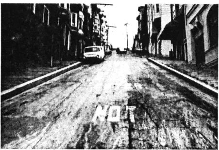
Fig. 2 Montgomery Street from Broadway
built element and its correlation with adjacent buildings is very different for these two situa-tions. Within a relatively short distance, the conflict of street grid and topography creates a changing variety of slope adaptations, necessary set-backs, and access variations.
The interrelation of street grid and topography
also influences circulation and parking. Very steep slopes require perpendicular parking, one way traffic, or a ban on through traffic. In areas such as Telegraph Hill, Buena Vista Park and Mount Davidson, the topography creates extreme con-straints on parking and traffic. (Fig. 2) The
situation around Alamo Square permits normal traf-fic cirulation and parking parallel to the side-walk.
2.12
GENERAL DESCRIPTION ON THE BLOCK LEVEL 2.121
CIRCULATION SYSTEMS
The original street width of twenty-five varas
(68'9" or 20.65 m) included the sidewalk area.
This distance was measured between lot lines on op-posite sides of the street. An average sidewalk width of 10 feet provided a space of 48'9"
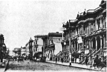
Fig. 3 Golden Gate Street near Webster Street
(1920)
Fig. 4 Webster Street from McAllister Street
(1977)
(14.625 m) for parking and vehicular circulation in both directions (Fig. 3) This width is suffi-cient for today's circulation standards. It per-mits parallel parking on both sides of the street and vehicular circulation in both directions. Only a few streets, such as Van Ness Avenue and Webster Street between Grove and Geary Streets, are wider than the typical street width; they generally function as traffic arteries (Fig. 4).
The generic street width of 68'9" also pro-vides sufficient lighting for buildings on both sides of the street and permits a range of land-scaping in the sidewalk area. This dimension of width also creates a correspondance between ele-ments on opposite sides of the street. The pro-portions of buildings and the distance between them create a street space where elements are per-ceived in morphological relation. Wider streets, such as the section of Webster previously mention-ed, do not have this quality. The distance be-tween buildings on opposite sides of the street is too large to generate a linear space with the
-closed character of more narrow streets.
In a section of the Western Addition between
Larkin, Webster, Haight and Geary Streets, the
BLOCK 830 A LON6 ALLEY PROVIDES VEHICULAR
830 0
CIRCULATION THROUGH BLOCK
Fig. 5 Block 830 (1976)
I
U
Fig. 6 Block 830, view from Laguna into Linden
basic block was divided lengthwise. This generated a long alley, which provided additional vehicular access to the inner block area. This subdivision was made in 1876, most likely to provide additional
small plots affordable by persons of lower income. Another reason for this different circulation
pat-tern may have been real estate speculation: smaller
plots were easier to sell and provided more profit. Because of the fixed location of major streets, the alley had to be narrow. Today, alleys function only as vehicular access to the back. In the
nine-teenth century, both sides of the plots between major streets and the alley were developed separ-ately, with buildings facing on both the major
streets and the alley. Buildings along major streets had the same size as those built in the basic blocks. Dwellings built along the alleys were smaller in depth and height. Block 830A is an example of such a plot subdivision (Fig. 5). Today, most buildings along the alley relate to the
building behind them which faces on the main street. The short alley is a variation of this circu-lation pattern. This subdivision is rare compared
to that created by the long alley. Nevertheless,
it is an interesting way to provide access to the 23
BLOCK 1154A
ShRT ALLEY
PROVIDES VEHICULAR
1154 B CIRCULATION THROUGH BLOCK
inner block and to develop this zone forresiden-tial use.
Dimensions of the main street limit possible lot arrangements. In this case, there is more space for each building facing on the alley than in blocks cut by a long alley. This makes it possible to locate deeper buildings along the alley. Block 1154B presents an example of this block type. As in block types with long alleys, most of the buildings are oriented to the major streets. The short alley provides access to seven buildings (Fig. 7). Because of the deeper lot di-mensions, buildings along the alley have set-backs.
Some short alleys have a continuous facade of attached buildings. The distance between facades
on either side of the alley is only 25' (7.5 m).
(Fig.8)
2.122
LOT SUBDIVISION
The basic block size north of Market Street is 412'6" x 275' (123.75 m x 82.5 m). These dimen-sions are in accordance with the grid laid down by Jean Vioget and are based on the vara module,
be-ing 150 by 100 varas. (Fig. 9a)
Fig. 9a Generic Block Area
Fig. 9b Generic Subdivision
into Six Parcels
Fig. 9c Lot Subdivision of Generic Parcels
Blocks without alley circulation were divided into six parcels, each fifty by fifty varas (137'6" x 137'6", 41.25 m x 41.25 m). (Fig. 9b) Parcels of these dimensions still exist in the Alamo Square area (e.g., Blocks 798 Grove and 824 Fell).
The majority of these parcels were divided fur-ther (Fig. 9c). Analysis of the lot subdivision shows that parcels at the corners have a variety of subdivision combinations while center parcels on the long sides of the block have similar subdivision pro-portions.
A parcel fifty varas wide was divided into five lots, each ten varas wide (27'6", 8.25 m). In-cluding areas from adjacent corner parcels, combi-nations of different lot widths were possible. The most common dimensions are 25' (7.5 m), 27'6" (8.25 m)
and 30' (9.0 m). Lots of these widths have a depth of 137'6", which provides an average ratio of
pri-vate land frontage to depth of one to five.
Subdivision of corner parcels was based on the importance of adjacent streets and type of develop-ment. If parcels were built with similar building
types (e.g., Block 776 Golden Gate), the lot
subdi-vision patterns were not as differentiated as they
were for individual developments with varying types and sizes (e.g., Block 824 Oak). By shortening lot
Intermediate lots
.Corner lots
.... K..e.y-lKey-lots
Fig. 10 Block 821
depth, it was possible to divide a corner parcel
in-to seven separate lots. 2.123
INTERMEDIATE, CORNER AND KEY-LOTS
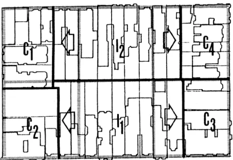
Three kinds of lot locations, resulting from different lot subdivisions and locations of generic parcels, may be defined. Each of these location types has specific characteristics which are repeat-ed in every block and may be definrepeat-ed as patterns of the existing block tissue (Fig. 10).
Intermediate lot locations. These are to be found along the long sides of a block. They usually have a depth of 137'6" (41.25 m). In some cases, the depths of intermediate lots in a block may dif-fer, but their combined depths equal 275' (82.5 m).
Corner lot locations. These may vary in depth and in orientation. In the typical lot location, a
lot is oriented to two streets. If a lot is orient-ed to the longer side of a block but shorter than
137'6", its location is called a corner location.
This means that the lot is influenced by lot subdi-vision patterns for the corners.
Key-lots. These are located between the cor-ner lots on the short sides of a block. They dif-fer from intermediate locations by depth, which may
Fig. 11 Block 821 Location Areas of Lots
be less than 137'6" (41.25 m) and oriented to the
short, instead of long, sides of the block.
To simplify lot location typology for the an-alysis and a later computer-aided evaluation
sys-tem, this study differentiates only two location types, based on the lot subdivision patterns of generic parcels. Key-lots are combined with cor-ner lots, becoming corcor-ner location areas; intermed-iate lots are combined to become intermedintermed-iate tion areas. Each block will have four corner loca-tion areas and two intermediate localoca-tion areas.
Analysis of sixteen blocks in the Alamo Square area indicates that the dimensions of the generic block are preserved in only 18.75 per cent of inter-mediate lot locations. Of the others, 15.6 per
cent are less than 137'6" wide and 65.65 per cent are wider than 137'6", demonstrating that lot sub-division was not bound by the dimensions of the
generic parcel.
This analysis also found different depths for corner location areas. Only 41 per cent of the cor-ner areas had the depth of the gecor-neric parcel; 59 per cent were smaller. The depth of individual lots in corner lot locations was reduced to increase the number of lots. Figure 11 shows the extension of the intermediate lot location area to the corners
Fig. 12 Block 754 Golden Gate
Fig. 13 Block 777 Fulton
Fig. 14 Block 803 Steiner
and reduction in the depth of corner location lots in Block 821.
2.13
GENERAL DESCRIPTION ON THE BUILDING LEVEL 2.131
BUILDING TYPES; NUMBER OF FLOORS
The townhouse with one or two main floors was the dominant building type in the Victorian develop-ment. In 1899, only 24.14 per cent of the
build-ings had only one main floor; 66.79 per cent were two main floors high (Fig. 12).
During the last eighty years, there has been an increase in the number of buildings with three main floors. The percentage of buildings with one main floor has decreased to 15.53 per cent. This change is a result of decreasing family sizes as well as the trend of larger middle class families to live in suburbia where lots and houses are not as expensive as in the urban region.
A large number of apartment buildings have been
built and provide many small units. Because of the building code regulation regarding density stan-dards, these buildings usually have three main floors (Fig. 13).l
1San Francisco Municipal Code, Part II, Chapter
A few higher buildings can be found in this area, for example, a seven-story apartment building on Steiner Street. This building is located on Alamo Square which provides enough distance from structures on the opposite side of the square to
permit a height of six main floors (Fig. 14)
In 1976, there were 1230 buildings in the sur-veyed area around Alamo Square of which only 27
(2.19 per cent) had more than 3 main floors.
2.132
TYPES OF PLOTS
The description of lot subdivision patterns in section 2.122 explains how lots of different widths
and depths were generated. These lots contain
build-ings of varying types, dimensions, and shapes. 2.133
CORRELATION OF PLOT AND BUILDING
The interrelation of adjacent buildings is important for the morphological situation of the streetscape. Victorian development was based on two elements: lot size and the dimension and lo-cation of the building which covered the whole or a part of a site.
For a large number of streets, the elevation of built elements is not continuous. Buildings may
A
Bi
B2
C
ATTACHED WET ATTAOE W1
MEmil.sMi
L~
3 3 0 S S 0 3 I1
MIECSS
3
RECESS NST. -s I-I'K)'
*3* A I I K) I ... , a 3 a e 3* S *IUIa
e
K)
~ S A RECESS ~I ~ OPE NIS - I* E1CENTER 11U)A
QQKYY
Q
Y
Bo3 BbB*510 Sobub Bo B~* 10*b SSB 6 jK
IKTN NIS OKI " IVVETE
as aU1eUUU
u
VI
U
UU
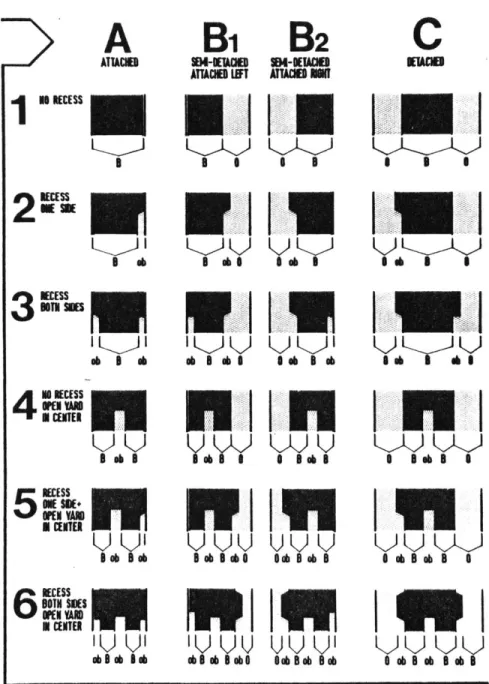
Os 8 Ob Iab o b Bob a Ae 0 a 8 Ob 8 A ebe semi-detached or detached. Some building types
have recess elements on one or two sides (see sec-tion 2.142), an entrance yard in the center, or a combination of both. The location of the
build-ings, their dimensions, and the width of a lot
gen-erate a variety of arrangements.
Figure 15 shows how the plot-building correla-tion is perceived from the street. This scheme typologizes situations in intermediate location areas. A, B1, B2, and C regulate the position of
a built element on a lot. Different forms of re-cesses, entrance yards, and their combinations are
shown under numbers 1, 2, 3, 4, 5, and 6. The com-bination of these two elements generates a type of zoning system perpendicular to the street.
2.134
ELEMENTS OF BUILDLING
The townhouse was the typical building type of the Victorian era. Although the number of
apart-ment buildings has increased since the nineteenth
century, only 16.7 per cent of the buildings in the surveyed area around Alamo Square are apartment buildings. Most buildings are townhouses. It is the townhouse which characterizes the streetscape.
30
U a
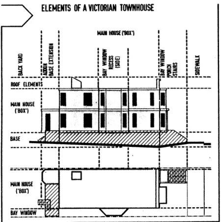
ELEMENTS OF A VICTORIAN TOWNHOUSE
Sa a - - - --- - - - -- - ---- ---ROOF ELEMENTSLj
j
MAIN HOUSE (BOX')I
I
0
1
I
a---r MAIN HOUSE CBOX1 ..WINDOW .I
III I!
I I I
'a * S S. a a a * S I I0
III
=, IIi
-.4 a a aI
-III'
Each townhouse dwelling can be differentiated
by its separate elements which together form the
complex environment, inside and outside, of each building. These elements are indicated in Figure
26. The base is the section of a building which
adapts the building to the topography. The box, or main house, includes all major living and cir-culation spaces. The roof area tops the building. Add-ons in the front and back may increase the vol-ume of the main house. Bay window elements in the front and along the side of a building are also specific elements of the Victorian townhouse.
2.1341
BASE
- The base is one of the most interesting ele-ments of a townhouse. Along with its function of adapting the rectangular box of the main house to
the topography of the site, the base is the section of a building where public space, the street and sidewalk, ends and private space, staircases and the garage, begins. The most important functions of this semi-public zone are to provide access to parking space in the base area, pedestrian access
to the building, and landscaping, if the building
is set back from the street.
31
i
Fig. 16 Elements of the Victorian Townhouse.- Base
C:- 1
P M
J
Z=-wM 1 I I= - -4 -
In the generic Victorian streetscape, these
different functions were heterogeneous (cf. Fig. 3).
Staircase elements, front gardens, and curb cuts created a differentiated environment for this zone.
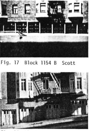
The trend to build apartment houses and con-vert townhouses into smaller units, coupled with the popularity of the car as an individually-owned Fig. 17 Block 1154 B Scott
passenger vehicle, required large amounts of park-ing space. Because streets do not provide all the required parking units, most base areas have be-come garages. The formerly differentiated base front has changed into a homogeneous wall in which garage doors are the dominant element. This pro-vides a maximum number of separate accesses to in-dividual parking spaces in the base, which now Fig. 18 Block 823 Hayes functions primarily as a container for cars. (Figs.
17, 18, and 19) The arrangement of continuous curb
cuts limits parking along the sidewalk, does not permit landscaping, and reduces to a minimum the visual quality of this zone.
In the sidewalk area, a variety of open stairs provide access to buildings. These stairs may
reach into the public zone (the sidewalk), as in Steiner Street, Block 826 (Fig. 20), or are a part
Fig. 19 Curb Cuts on a Very 32
Fig. 20 Block 826 Steiner
Fig. 21 Block 826 Fell
of the landscaped, semi-public front zone, as in
Fell Street, Block 826 (Fig. 21).
In other situations, they do not extend over the front lot line. Figure 22 shows a staircase elevation on Buchanan Street, Block 819. The steep slope and different heights of adjacent bases create stairs of different widths, directions, and depths. The base in this section of the street has a resi-dential function. This means that additional stair-cases provide access to residential spaces located below sidewalk level. The entrance to these
base-level residential areas is very often under the
landing of the stairs, which provide access to the first floor.
Buildings with a very high base often have a staircase parallel to the street, inside or outside
the building. Figure 23 shows a line of similar row houses with similar stairs, parallel to the sidewalk. Here, the base is used as residential
...
Fig. 23 Block 819 A Linden
Fig. 22 Block 819 Buchanan
Fig. 24 Block 775 McAllister
I 2
Fig. 25 Block 774 Golden Gate
space with its own entrance, located under the landing of the main staircase.
The zone between public sidewalk space and private building space may fulfill various "micro-functions" which do not dominate a whole street, but vary from site to site. To contain a function, the space in which this function occurs must be equivalent to the requirements of the function.
Differing set-back depths provide various pos-sibilities of use for this area. While deep set-backs of more than fifteen feet create spaces which separate the public and private areas by an autono-mous zone such as a front yard, set-backs with less depth generate a space with a different quality. A
small set-back margin permits only minor activities
or landscaping. Nevertheless, such an arrangement
increases the attractivity of the base zone for passing pedestrians and creates a variety of
indi-vidual elements along a street.
On McAllister Street, Block 775, the ten-foot set-back margin contains elements for access to the first floor and base level of the main building, as
well as a bay window (Fig. 24). The small set-back depth is not sufficient for a large playground, but large enough for a building-related playground for
ELEMENTS OF A VICTORIAN TOWNHOUSE
H *OIHSUSEESX'
---...-...-...--...-..-...
_-.-.-.-children, who exhibit a consciousness of the semi-public quality of this space by storing their toys behind the wall which separates this area from the sidewalk.
Minor set-backs,(as shown in Figure 25 (Block
774, Golden Gate), also provide space for
addition-al landscaping.
2.1342
MAIN HOUSE OR BOX
The main house, or "box", is the dominant ele-ment of a building (Fig. 26). The balloon frame construction method used creates a rectangular con-tainer for major indoor residential functions. This box is placed on the base, and accomodates up
to three main floors. In 1899, only 0.43 per cent
of all buildings had more than three floors. Even today, there are only 27 buildings (2.25 per cent) in the surveyed area of Alamo Square with more than three floors. These buildings are defined as non-thematic and will not be considered for the general analysis.
The box responds to the problems of maximizing the size of the house, providing enough light for the interior, and fulfilling constraints of the
site dimensions and adjacent situations.
35 Fig. 26 Elements of the Victorian Townhouse
The floors of the Victorian townhouse were organized
accord-ing to the "railroad plan," rooms are arranged along one side of
a hall. The depth and width of each box may vary when adapted to more specific constraints of a site.2
The average ceiling height of the Victorian house is about eleven feet, high when compared to today's standard of eight to nine feet. This height provides very good lighting for the
inter-ior and permits deep rooms.
2.1343 ROOF
The roof area of a building contains built elements of resi-dential or technical use (e.g., a chimney). A roof area is defin-ed as the space locatdefin-ed at the top of a building which has no pri-or fpri-ormal relation to the front facade. Victpri-orian buildings
exhib-it a very differentiated roofscape on some streets, created by various elements of the style and their interrelations. New
build-ings generally do not fulfill this criterion. Recommendations will
be proposed which assimilate this characteristic for new designs.
2.1344
ADD-ONS
The main house is a container for basic indoor housing func-tions. Specific requirements of the dweller often necessitate
ex-2For detailed information on the characteristics of floor
plans for dwellings and flats, see the report, "Urban Form and Change."
expansion of the space provided by the box. It is possible to add extra space to a dwelling by attaching add-ons to the dwelling.
Most add-ons are attached to the back of a building, where they may be attached along the complete height of the building. When townhouses are converted to flats, add-ons are usually built
on the back, to provide an additional kitchen or bedroom.
Add-ons are not attached to the main floor area on the front of a building. Additional built elements in the front of a box are located only in the base area, to provide additional parking space. For commercial use, an add-on may extend into the first floor space, to provide a second level for a shop or an office.
2.1345
CHARACTERISTICS OF THE VICTORIAN RESIDENTIAL BUILDING
The bay window is not an architectural element specific to the San Francisco area, but it is used there in a very unique way and has a strong importance in the elevation fabric of the street.
Bay windows amplify lighting and view for rooms along the front facade. Although they occur only occasionally along the back of existing buildings, they dominate the front (in corner lo-cations, though, only along the street-oriented sides) and cover part of the space which lies between the public space, the street and sidewalk, and the private space, the main house or box.
Bay windows produce a set of vertical volumes in front of boxes and create, with entrance porches, staircases, and entrances, a breakdown in the continuity of these boxes. While different set-37
Fig. 28 Block 822 Steiner
Fig. 29 Block 778 Fulton
back depths modulate the street elevation in the box scale, bay windows divide the mass of a single box into a set of smaller elements.
This system of breaking down the continuity of front facades along the street elevation gener-ates two levels of depth. Major differences in depth are produced by the set-back of a building, up to twenty feet, while a rhythm of more shallow variations, from two to five feet, is created by bay windows of different sizes and shapes (Figs.
27, 28, and 29).
Shapes of the Victorian bay windows differ, according to the style in which the building was built. Stick Style preferred rectangular bay win-dows. Queen Anne Style buildings have round bay windows. The Italianate Style placed the sides of
bay windows at an angle of thirty to sixty degrees
to the front facade.
The width of these elements varies from seven
to ten feet. Post-Victorian styles and a large
number of blended styles assimilate the bay window but change dimensions and materials. The San Fran-cisco Building Code regulations limit bay window depth in relation to the width of the adjacent side-walk, resulting in a shallow but wider type of
Bay windows are located on the side as well as the front of a building, according to the location of a building and the decision of the builder.
The surface area where special concern is placed on the design and ornamentation of the fa-cade is called the public fafa-cade. This is the out-side of the box, the envelope of the private space, which faces the public and represents the dweller's individual taste to the public. Elements in the public facade area display a rich vocabulary of styles and ornamentation, while the rest of the en-velope is very simply treated. Figures 30 and 31 show simple construction of the back of two
Victor-ian buildings which have very ornate front facades.
In these cases, the bay window elements are repeated in the back.
The balloon frame technique permitted mass production of houses. A large variety of prefab-ricated details was available for ornamentation of public facades. Armed with pattern book and archi-tectural catalogues,3 even an unimaginative builder could create a dwelling which we find today amazing.
3
An example is Architectural Elements, The
Tech-nological Revolution. (Princeton: Pyne Press.)
Fig. 31
Fig. 30
Fig. 32 Block 1179 McAllister
Fig. 33 Block 777 McAllister
Brakets, spindles, decorative shingles, oriels and bays, sawn wood ornaments, verge boards, tiles, etched and stained glass, incised ornament, appliques, soaring chim-neys - there were literally hundreds of de-sign variations and materials that the Vic-torian builder could use to make a house "beautiful" - and distinctive fr m others in the same architectural style.
A few examples of such ornamentation for bay windows are presented in Figures 32, 33, 34, and
35. Although these examples are based on the same
construction dimensions, they differ in shape and detail.
The bay of the McAllister, Block 1179, example.
(Fig. 32) is based on the Stick Style which pre-ferred a rectangular shape of bay window element (squared bays) and emphasized the bay by decorative strips. Wooden ornaments over the windows are based on the Italianate Style.
The building on McAllister, Block 777 (Fig. 33) is another example of the Stick Style with
Victor-ian Gothic ornamentation. The sawn wood elements
are very colorfully painted, and the windows are decorated with stained glass.
Judith Lynch Waldhorn, A Gift to the Street. (San Francisco: Antelope Island Press, 1976) Fig. 34 Block 777
McAllister
Fig. 35 Block 798
Fig. 36 Russian Embassy Fig. 38 Block 777 McAllister Fig. 37 Block 1179 McAllister Fig. 38 Block 1155 Golden Gate
Figure 34, McAllister, Block 777, shows a slanted bay with pipe stem colonnetteat the edges, a typical representative of the Italianate Style.
While Figures 32, 33, and 34 show an emphasis of vertical elements with high and narrow window segments, the windows in Figure 35 are nearly square. This example, from Steiner Street, Block
798, represents a blend of styles. The shapes of
the bays are based on the Stick Style, while the window forms and ornamentation are rooted in the Colonial Revival Style.
Porches, as well as bay windows, are treated
as elements of the public facade. They display the
same basic formal elements, but very often have
additional ornamentation. Figures 36 and 37 show
columns supporting the balcony over two entrances. The capitals of these cylindrical elements are
richly ornamented with acanthus leaves, derived
from the Corinthian order.
Ionic columns decorate the porch in Figure 38, while columns in Figure 39 are rooted in romanesque patterns. These two porches emphasize their impor-tance as representative architectural elements with additional elements such as the putto in the arch
or colorful sawn wooden ornamentation based on an
Islamic design.
Variations in ornamentation, especially, made a single building distinctive and generated the in-dividuality of each public facade, constrained by construction dimensions and basic styles.
2.14
CORRELATION OF BUILDINGS
The description of criteria for single build-ings demonstrates the variety of individual built elements in the urban block tissue. This phenom-enon is not unique to San Francisco. The extremes of the topographical situation, combined with the street grid, are specific to this area and create morphological relations of built elements which can be found only here.
2.141
THE BASE AREA
The base area displays not only differentia-tions in access patterns and set-back dimensions, but also in the correlation of building size and plot width (cf. section 2.133). A bay window at the side of a building generates a recess which in-terrupts the continuity of the front facade eleva-tion. Such recess elements create a type of ob-margin perpendicular to the street. An opening
between two buildings (Fig. 40) can provide access 42 Fig. 40 Block 825 Fell
for parking in the rear yard, be a side yard, or provide additional pedestrian access to the side. Such side clearances are generated by the loca-tion of a building on a wide lot.
A building may be detached or semi-detached in relation to neighboring buildings, generating one or two 0-zones perpendicular to the street.
Combinations of ob-margins and 0-zones are also possible. An example of an opening for ve-hicular circulation, in the base area under the main floor area, is shown in Figure 41.
2.142
MAIN FLOOR AREA
Adjacent main floor areas may differ in di-mensions of width and height, in types of bay win-dows, and in ornamentation. According to the loca-tion of a building on a lot, main floors have the same position patterns as bases (attached, semi-detached, or detached) and generate the same ob-margins or 0-zones on the main floor level.
De-pending on the top of the base, with different heights for each building in a sloping situation, the height of main floors also varies from build-ing to buildbuild-ing. Buildbuild-ings step with the slope which generates different levels for the same Fig. 41 Driveway Under a Recess
floor in adjacent buildings (Fig. 43). Normally,
buildings step parallel to a slope, but it is also possible that the stepping, moves against the slope, if the number of main floors differs from one
building to the next (Fig. 42).
2.143 ROOF AREA
In the roof area the same correlation criteria
as in the main floor can be seen. Roofs step with
the slope; they differ in cornice height. As well
as this variation, they break the continuity of the
Fig. 42 Block 820 B Fell roofscape by different shapes of such elements as
cornices and gables.
Figure 44 (Steiner, Block 827) shows the roof detail of two attached buildings. Although they have the same number of main floors, they differ in height because of the steep slope and different base adaptations.
Figure 45 is an example of how different
cor-Fig. 44 Block 827 nic heights and roof shapes create a variety of
Steiner
forms on the roof level.
.1P.
....
2.15
FORMAL CHARACTERISTICS OF THE STREETSCAPE
A survey analyzed the streetscape of fifty
Fig. 43 Block 778 Fig. 45 Block 822 blocks in the Alamo Square area. Although there
Fig. 46 Webster Street
AWE%
Fig. 47 Block 776 Golden Gate
was a continuity of set-backs, recesses, and the change of house type patterns in most streets, some sections indicated a very strong similarity of elements.
Similar row houses along a section of Webster Street (Fig. 46) are all located with their front facades at the sidewalk. Each building has the same width (25', 7.5 m). Bay windows have the same proportions; every other building has the same roofing ornamentation on the top bay window. Individual buildings differ only in color and orna-mentation.
In comparison, a group of buildings along Golden Gate, Block 776 (Fig. 47), has the same height, access patterns, location and width. Each single unit is detached from adjacent buildings, with the same distance between each one. Even the
bay windows resemble each other in shape and loca-tion on the facade. These buildings differ in color, ornamentation, facade material, and in de-tails of roof elements.
These two examples present situations where the generic parcels were subdivided into lots of equal size, and these lots were developed by the same builder. One group exhibits more variation.
Fig. 48 Block 803 Steiner
Another development example is the complex of houses along Steiner Street at Alamo Square (Fig
48). This ensemble was constructed from the same
floor plan by the carpenter/builder, Matthew Kav-anaugh around 1895. Each building has a unique ornamentation on the front facade, but exactly the same location for bay windows, balconies, and porches. The charm of this ensemble is the slight difference of gable ornamentation, porch balusters, and coloring.
The examples shown in Figures 46, 47, and 48 are not typical of the area in general, but they
visualize well the influence of the individual on buildings built at the same time. Variations in
the buildings on Golden Gate were spontaneous, gen-erated by the dwellers. Variations in the ensemble
along Steiner Street were planned by one person, but are based on prefabricated architectural parts offered by the building industry in the nineteenth
century.
In contrast to these homogeneous groups of structures, heterogeneous groups may be found in this area. These buildings differ not only in size, style, and material, but serve different functions
as well (Fig. 49).
Fig. 50 Block 829 430 Webster Fig. 52 Block 775 McAllister/ Pierce Fig. 51 Block 830 Fell/Laguna Fig. 53 Block 805 Hayes
As well as emphasizing corner locations with apartment buildings (see section 2.131), the gener-ic Vgener-ictorian streetscape includes specifgener-ic corner elements. The most common method of emphasizing a corner was to orient a bay window to both sides, creating a 270 degree bay. Figure 50 shows a sit-uation on Webster Street, Block 829, where a round bay window wraps around a corner. Victorian styles also emphasized the corner element with cornice ornamentation, as in a building at the corner of Fell and Laguna Streets, Block 830 (Fig. 51). In other situations, such as the corner of McAllsiter and Pierce, Block 775 (Fig. 52), and the corner of Hayes and Buchanan, Block 805 (Fig. 53), corner location is emphasized by round corner towers.
This description of different morphological elements and their correlations is only a brief summary of the complex morphology around Alamo Square. More detailed information will be provided
in the report, "Urban Form and Change."
Neverthe-less, this study documents the basic elements of
the tissue and indicates tissue patterns.
This study does not include an evaluation of these morphological situations. Historians, plan-ners, environmental pychologists, sociologists,
and economists would be needed to evaluate this situation in its entire complexity. For the further development of new tissue rules, these major patterns will be taken into consideration.
2.2
CHANGE WITH(OUT) LOSS
-
RENEWAL AND RESTORATION
PROJECTS AROUND ALAMO SQUARE
2.21 '
PROBLEMS OF URBAN CHANGE
The flexibility of an urban tissue can be measured by its capacity to permit changes which adapt the structure to modern requirements. These newly created necessities may be the result of differing life styles or the demands of additional functions. The change of an urban environment is a physical change.
Build-ings may be extended, renovated, and torn down, to be replaced by
new ones.
The Victorian block tissue contains elements which permit this kind of permenant regeneration. The subdivision of lots into
small plots and individually-owned single units enable change on a small scale.
Today, more and more land is owned by fewer individuals. This
means that sites can become larger, as large as a whole block. Change is not any longer a matter of a group of house-owners, but becomes a project, which must maximize profit for a small group of financiers who have little or no interest in the living quality of the area or concern for the architectural adaptation of a new design to an existing situation.
While change in a living environment takes a certain amount of time - in the Alamo Square area, the change from houses to
Fig. 54 Block 778 Fulton Street (1910)
flats took eighty years and is still an ongoing pro-cess - new building materials and methods produce
rapid change on a large scale, sometimes in only a few months. Very often, new developments have not only economic and construction-related constraints, but are built in a popular design fashion which can be defined as modern but has little or no respect
for the formal context of the neighborhood.
The change in a single block element, a build-ing, can be minor. Figures 54 and 55 show two
houses of the same type on Fulton Street, Block 778. The upper picture shows these two houses in 1910.5 They are smaller than their lots and leave a ten-foot (3 m) side clearance between them. They have public facade ornamentation on the front only, and ornamented gables over the roof-story windows.
The second photograph presents the change after sixty-five years. The main elements of these dwel-lings have not changed. The ornamentation on the gables has been removed, and the finish on the front facades has been simplified (perhaps under the influence of the International Style). A change of functions for main floor areas cannot be
5San Francisco Historical Society Photo
Collec-tion.
Fig. 56 Block 757 (1976)
inferred from these photographs, but one can see that part of the base of the house on the right
has been converted to a garage.
2.22
NEW DEVELOPMENTS
Modern standards of housing, construction meth-ods and technology, and architectural trends will influence the form of future block tissues. They can either ignore existing life styles and archi-tectural morphology or adapt new designs to the ex-isting situation by assimilating the most character-istic elements of the surrounding environment.
Block 757 was subdivided into twenty lots be-fore 1931. In contrast to most residential lots, this block contained fifteen non-residential func-tions and only thirty-three residential units. The existing physical structure of this block was torn down for a new development, which gave 211 families
Fig. 57 Courtyard
51
Fig. 59 Block 802 (1976)
a home and reduced building coverage to 18.4 per
cent. (Figs. 56, 57, 58)
The public housing project in Block 820 is a low rise development (Figs. 59, 60). Three open building blocks, arranged diagonally to the
exist-ing built element layout, provide two inner
court-yard zones used for parking. Facades on the street are continuous and ignore all formal aspects of the neighborhood (Fig. 60). Figures 61 and 62 show two
other developments, a low rise type in a schematic
set-back layout (Fig. 61), and one with more
differ-entiated breaks in the continuity of the facade.
(Fig. 62) Fig. 61 Block 748 Turk Fig. 62 Block 780 52 Fig. 60 Block 820
Fig. 63 Block 1079 Golden Gate at Buchanan
Fig. 64 Building with Tower to Emphasize Corner
Several approaches to the assimilation of formal elements of the block tissue can be seen. A public housing project at Golden Gate, near Buchanan, increases the height of the building by one floor at the corner locations. Window elements are organized as bays on the front of the main fa-cade. Large vertical openings for staircases re-peat the vertical rhythm which dominates the Vic-tornian streetscape (Fig. 63).
Figures 64 and 65 provide other examples of new structures in corner locations. The corner is treated differently in each design. A tower con-struction (Fig. 64) and a corner bay (Fig. 65) give this part of the building a specific accent.
Fig. 65 Building with Bay to Emphasize Corner 53
2.23
ARCHITECTURAL GROUPINGS FOR MAPPING PURPOSES
The San Francisco Planning Department is con-scious of the unique Victorian residential areas. Their efforts are concentrated not only on sections of the Western Addition, but in other districts of San Francisco which have a built environment worthy of preservation. An analysis has been made on the individual house, as well as the regional (zoning),
level. The important elements of the building
types were classified and their positions relative
to the sidewalk notated (Fig. 66).
A survey of styles of the Victorian
street-scape in other parts of San Francisco was
consider-ed as well. Figure 67 shows a list of the various styles which occur in the city region. The five main groups, California Tradition, Nineteenth Cen-tury Ornamental Styles, American Traditional and
Regional Styles, Classical Root Styles, Exotic Styles, and Modern Root Styles, can be divided into
sub-styles and mixtures of these sub-styles.
Buildings along a street are evaluated
accord-ing to certain criteria regardaccord-ing their
relation-ship to adjacent buildings and their architectural design. The evaluation form presented in Figure 67 contains information about the general condition of
Fig. 66 Street Elevation with Analysis of