EcoGRAFI
2nd International Conference on Bio-based Building Materials & 1st Conference on ECOlogical valorisation of GRAnular and FIbrous materials June 21th - 23th 2017
Clermont-Ferrand, France
THE COMPATIBILITY BETWEEN WOOL FIBERS AND CEMENTITIOUS
MORTARS
A. P. Fantilli1*, D. Jóźwiak-Niedźwiedzka2, K. Gibas2, J. Dulnik2
1 Politecnico di Torino, DISEG, Corso Duca Degli Abruzzi 24, Torino 10129, Italy 2 Institute of Fundamental Technological Research, Polish Academy of Sciences,
Pawinskiego 5b, 02-106 Warsaw, Poland
*Corresponding author; e-mail: alessandro.fantilli@polito.it
Abstract
The addition of natural fibers residue in cement based materials can be a sustainable technological alternative for traditional dispersed reinforcement, and can improve the performance of brittle matrix materials. The presence of a wool reinforcement can increase the fracture toughness and, at the same time, can reduce the environmental impact of cementitious mortars. The beneficial effects are similarly to those observed in presence of vegetal fibers (e.g., hemp), which have been largely investigated in the literature. However, there are some limits in the use of wool fibers due to their chemical compatibility with the cement matrix, as they can dissolve in alkaline environments. In the present paper, to investigate the compatibility between wool fibers and cementitious mortars, laboratory prototypes have been taken into consideration. Three series of wool-reinforced mortar beams have been cast and cured in water (20°C) or in dry conditions (temp. 20 °C, 50% R.H.) for some days. Portland-limestone cement CEM II has been used, whereas the content of fibers has been limited to about 1% in volume to maintain the workability of the mortars. To investigate the chemical compatibility, and the subsequent effects on the mechanical performances, prototypes have been tested in three point bending. After the mechanical test, the mortars microstructure was evaluated through SEM images and by thin section in transmitted light, in order to individuate a possible relationship between the dissolution of wool and curing conditions. The microstructure observation revealed the capability of wool fibers to bridge the cracks, and to reduce the brittleness of plain mortars. The differences in the mortars microstructure due to alternative curing conditions were also observed and described in the paper. Accordingly, wool could be effectively used to reduce the plastic shrinkage of cement-based composites, like the industrially manufactured polypropylene fibers.
Keywords:
Wool fibers, Plain cement-based mortar, Fiber-reinforced mortar, Polypropylene fibers, Three point bending tests, SEM analyses
1 INTRODUCTION
The fulfilment of ecological requirements, concerning low energy consumption in the construction industry, and the application of waste materials in building technology as well, is a necessity. Nowadays the continuous increase in the amount of waste from various processes, and the depletion of natural resources, forces researchers to find new possibilities to reuse waste in concrete technology and building materials. In the last decades, construction industry has adopted eco-friendly practices to enhance the performances of cement-based composites. Among them, vegetal fibers, made with bamboo and hemp, have been used to reinforce some cement-based composites, [Pacheco-Torgal et. al. 2011]. Indeed, these natural fibers are usually stronger and more environmental friendly than synthetic fibers, and can improve the mechanical performances of cementitious
mortars, [Hamzaoui 2014]. Some animal fibers, such as sheep’s wool, have also begun to be marketed and promoted as an alternative insulating material in building constructions [Corscaddena et. al. 2014]. However, about 75% of the wool produced by the European sheep farms cannot be used by the textile industry. The amount of this unused wool is around 150 million tons per year, to which the wool contained in other end of life products (e.g., fitted carpet), and in the waste of the textile industry, has to be summed [Schokker et.al. 2010].
Taking into account the availability of natural sheep wool as waste material, a research work was carried out to test the potential benefits of producing sustainable cement based materials. The purpose of this preliminary research was to design and characterize some cement-based composites with multifunctional addition of unused wool fibers. The
ICBBM & ECOGRAFI 2017 fundamental mechanical properties of the new
composites, including the microstructure analysis, were investigated.
2 EXPERIMENTAL PROCEDURE
The results of three experimental campaign, performed for the first time on cementitious mortars reinforced with wool and polypropylene fibers, is described in the following sections. The experimental procedures are in accordance with the rules reported by EN 196-1 [EN 196-1 2005].
2.1 Materials
The main components of the mortars herein investigated are:
• Cement CEM II/B-LL 32.5 R • Tap water
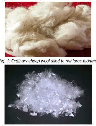
• CEN Standard sand, consisting of siliceous rounded particles, whose size distribution lies within the limits given in Tab.1 [EN 196-1 2005]. To the traditional mixture suggested by EN 196-1 [EN 196-1 2005], a suitable amount of ordinary (Fig.1) and polypropylene fibers (Fig.2) are added.
Fig. 1: Ordinary sheep wool used to reinforce mortars.
Fig. 2: Polypropylene fibers used to reinforce mortars.
The density of both wool and industrial polypropylene fibers is about 1.0 g/cm3.
With these materials, the following mortars were cast: • M = Plain mortar, in which the sand/cement and
water/cement weight ratios are 1:3 and 1:2, respectively [EN 196-1 2005].
• W = Fiber-reinforced mortar, containing ordinary wool (Fig.1). This mortar is prepared with sand/(cement + fibers) and water/(cement + fibers) weight ratios of 1:3 and 1:2, respectively. As wool fibers absorb water, the fiber content is subtracted from the cement content [Hamzaoui 2014].
• F = Polypropylene Fiber-Reinforced Mortar, prepared with sand/(cement + fibers) and water/(cement + fibers) weight ratios of 1:3 and 1:2, respectively.
As shown in Tab.2, which reports the weight composition of all the mortars, the W and F mortars are reinforced with 10 grams (about 1% in volume) of both wool and polypropylene fibers.
2.2 Specimens and test setup
Three specimens were cast per each mortar described in Tab.2. According to EN 196-1 [EN 196-1 2005], all the specimens are prisms with the dimensions of 40 40 160 mm (Fig.3). The prisms were demoulded one day after casting and stored in different ways, then three point bending tests were carried out. The external load P was applied through a Baldwin-Zwick loading machine, having a load capacity of 500 kN. Tests were performed by driving the displacement of the loading cell, whose stroke moved at a velocity of 0.5 mm per minute. Both the applied load P and the midspan deflection of the beam, were recorded during the tests, till the complete failure of the specimen (Fig.3).
After the bending tests, crack surfaces were epoxy-impregnated and thin sections were prepared from mortars. Specifically, the specimens were first impregnated, then cut into slices, and finally vacuum impregnated. Epoxy resin used for impregnation contained a fluorescent yellow dye. The mortar specimens were ground and polished to 20 ± 2 µm thickness thin sections. Thin section image acquisition was performed using an Olympus BX51 microscope in plane-polarized light (PPL).
The SEM analysis were conducted on fresh split surface of the mortar specimens.
Fig. 3: Three point bending tests for cementitious mortars [EN 196-1 2005].
2.3 Test results
Fig.4a shows the load-deflection (P-d) diagram obtained in each test, from which both Pmax and the
corresponding displacement, dp , are measured. As the
ductility, and the fracture toughness, of the cementitious mortars can be improved by the presence of fiber-reinforcement, also the post-peak diagram reported in Fig.4b is taken into consideration. On the ordinate of such diagrams, the values of the normalized load (with respect to Pmax ) are reported.
Conversely, the difference between the post-peak deflection and dp is on the abscissa. All the post-peak
diagrams are limited to the value d - dp = 0.2 mm.
The ductility of the mortars herein investigated are quantified by calculating the area AF delimited by the
post-peak curves of Fig.4b. If this value is multiplied by the flexural strength, a sort of fracture toughness in bending can be attained.
Tab. 1: Particle size distribution of the sand [EN 196-1 2005].
Square mesh size
(mm) 2.00 1.60 1.00 0.50 0.16 0.08
Cumulative sieve residue
(%) 0 7 ± 5 33 ± 5 67 ± 5 87 ± 5 99 ± 5
Tab. 2: Compositions of the mortars.
Fig. 4: Results from the three point bending tests on cementitious mortars: (a) load-deflection diagram; (a) relative load vs. post peak deflection.
3 FIRST SERIES OF TESTS
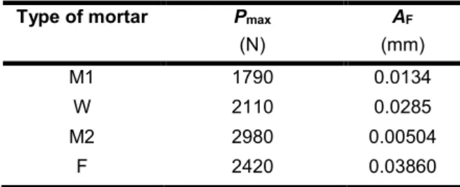
In the first series of tests, specimens were stored for 28 days in dry conditions (temp. 20 °C, 50% R.H.) before testing in three point bending. Tab.3 reports all the main parameters measured in this first series of tests. As the specimens reinforced with polypropylene fibers were cast, and tested, three months later, two plain mortars, named M1 and M2, are here considered as the reference of W and F mortars, respectively. Although the type of cement and the composition are the same, Pmax of W mortar is higher than the
maximum load carried by M1 mortar. Whereas, the strength of F mortars is lower than that of M2. However, the values of AF, which is a measure of
ductility, reveal the effectiveness of the fibers. Both for wool and polypropylene fibers, there is a remarkably increment of AF with respect to the corresponding
values of the plain mortars. In other words, wool filaments can work as a fiber-reinforcement. Indeed, a SEM image of the cracked surface of the W mortar
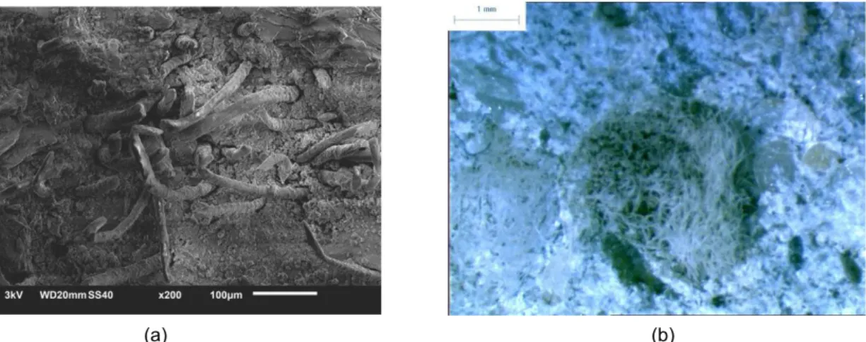
(Fig.5a) reveals the presence of wool filaments that tend to bridge the crack as industrial fibers do. Nevertheless, wool filaments are much longer than polypropylene fibers and tend to create bunches (see Fig.5b). For this reason, the increment of AF with
respect to the corresponding plain mortar, is higher in the case of polypropylene fibers (i.e., F specimens) than in W mortar.
Tab. 3: Results of the tests performed on a first series of specimens.
Type of mortar Pmax (N) AF (mm) M1 1790 0.0134 W 2110 0.0285 M2 2980 0.00504 F 2420 0.03860 Type of mortar Cement (g) Water (g) Sand (g) Wool (g) Polypropylene fibers (g) M 450 225 1350 - - W 440 225 1350 10 - F 440 225 1350 - 10
ICBBM & ECOGRAFI 2017
(a) (b)
Fig. 5: Characteristic part of the W specimen (not stored in water) with visible bunches of the wool filaments: (a) SEM observation, scale bar =100 µm, (b) stereomicroscope, reflected light, scale bar =1000 µm .
4 SECOND SERIES OF TESTS
In the second series of tests, specimens remained in the molds for 1 day and then were stored for 27 days in water (20°C), before testing in three point bending. As the specimens reinforced with wool and those with polypropylene fibers were cast in the same day, a single plain mortar is herein considered as a reference. Tab.4 reports all the main parameters measured in this second series of tests. In this case, the wool filaments are no longer effective as in the first series of tests. Indeed, the maximum load reduces in both W and F mortars, even if in the case of the wool reinforcement the reduction is the largest. In addition, in the case of W mortar, the post-peak ductility completely disappeared.
Tab. 4: Results of the tests performed in a second series of specimens.
Type of mortar Pmax (N) AF (mm) M 3620 0.00754 W 2350 0.00635 F 3044 0.0351
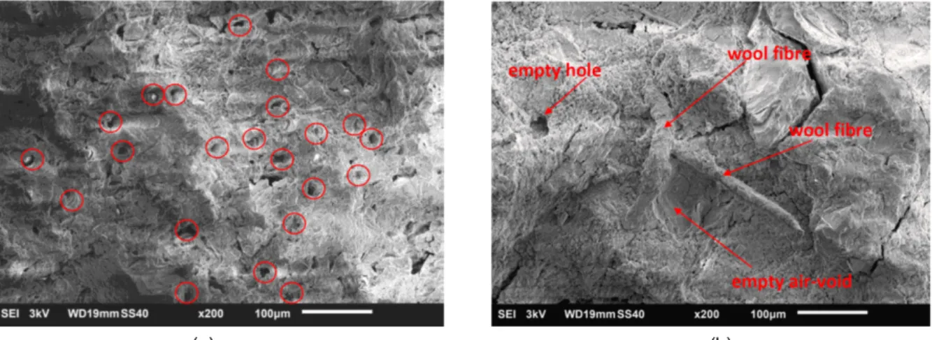
This is due to the fact that some reaction took place and the wool was corroded. The result of such a phenomenon is clearly evident in Fig.6. In particular, crack surface of a W specimen shows the presence of holes, instead of wool filaments (Fig.6a). As appears in Fig.6b, the specimen is full of empty channels.
In Fig.7 a lot of small (about 10 microns) gaps/holes can be seen, where fibers were probably used to be. All the air-voids are empty, and any ettringite needles or portlandite plates are present. Nevertheless, just a few fibers are still in the matrix, but these fibers are covered by something similar to a reaction product (Fig.7b).
This phenomenon is not always dangerous. Indeed, polypropylene fibers are generally used to reduce the deleterious effect of shrinkage, which occurs within some hours after casting. Thus, if wool can resist for few days in alkaline environment, it is as effective as polypropylene fibers.
To check the chemical resistance of wool, a flake has been put in a NaOH solution with a pH = 12.4. After 3 days, the flake is more or less the same. In other words, it seems that wool could be corroded in alkaline
environment, but the corrosive reaction lasts more than 3 days. Accordingly, wool can substitute polypropylene fibers for mitigating the cracking of early age concrete. Of course, this is possible also because the corrosive reaction is not expansive.
5 THIRD SERIES OF TESTS
In the third series of tests, specimens remained in the molds for 1 day and then were stored for only 3 days in water (20°C), before testing in three point bending. As the specimens reinforced with wool and those with polypropylene fibers were cast in the same day, a single plain mortar is herein considered as a reference. Tab.5 reports all the main parameters measured in this third series of tests.
Tab. 5: Results of the tests performed in a third series of specimens.
Type of mortar Pmax (N) AF (mm) M 1300 0.00332 W 1040 0.0102 F 998 0.0444
Compared to the values measured in the previous tests, Pmax is very low, because the tests have been
performed just 4 days after casting. As expected, at this stage the wool can guarantee a post-cracking ductility. Indeed, the average value of AF is remarkably
higher than that of plain mortar.
Thus, if the mortar reinforced with wool filaments is stored only 3 days in water after casting, i.e. the time of plastic shrinkage, the corrosion is not so relevant. After cracking, both wool filaments and polypropylene fibers appear on the crack surfaces, as shown in Fig.8. However, the values of AF of the mortar containing
wool should be increased in order to reach the same value of the specimens reinforced with industrial fibers. To this end, wool filaments cannot be added to the matrix in the form flakes (Fig.1) but in the form of short fibers, as the industrial polypropylene fibers (Fig.2). In other words, wool can be used to contrast the deleterious effects of plastic shrinkage, even if it should be better distributed within the mortar.
EcoGRAFI
2nd International Conference on Bio-based Building Materials & 1st Conference on ECOlogical valorisation of GRAnular and FIbrous materials June 21th - 23th 2017
Clermont-Ferrand, France
(a) (b)
Fig. 6: Characteristic part of the specimen W (stored in water) with visible empty spaces in the matrix, instead of wool filaments; plain polarized light PPL: (a) 1- air-voids, scale bar =500 µm, (b) 1- aggregate, 2 – matrix, scale
bar =200 µm.
(a) (b)
Fig. 7: The SEM microphotographs of the specimen W (stored in water) with visible empty holes where used to be a wool fiber, scale bar = 100 µm.
Fig. 8: F specimen (on the left) and W specimen (on the right) after bending tests.
6 CONCLUSIONS
From the results of the experimental investigations previously described, and conducted on mortars reinforced with wool and polypropylene fibers, the following conclusions can be drawn:
• The addition of wool fibers does improve the performance of cementitious mortars, which behave as those reinforced with polypropylene fibers. However, this is true when the mortars are cured for 28 days in dry conditions (temp. 20 °C, 50% R.H.)
• Conversely, if the specimens were stored for 28 days in water (20°C) after casting, the beneficial effect of wool is not observed. Indeed, an alkaline reaction takes place and the wool corrodes completely.
• Nevertheless, wool filaments can resist more than three days in the alkaline environment before their complete dissolution. Thus, they can be used to contrast the effects of plastic shrinkage, similar to the industrial polypropylene fibers.
Finally, further experimental campaigns need to be performed to optimize the shape of wool filaments, in order to have wool and industrially produced fibers with the same aspect ratio.
ICBBM & ECOGRAFI 2017
7 ACKNOWLEDGMENTS
Part of the work was financed by the Italian Ministry of Education (Prin 2015).
8 REFERENCES
[EN 196-1 2005] EN 196-1. Methods of testing cement -Part 1: Determination of strength. European Committee for Standardization, 2005.
[Hamzaoui 2014] Hamzaoui, R., Guessasmam S., Mecheri, B., Eshtiaghi, A.M., Bennabi, A.; Microstructure and mechanical performance of modified mortar using hemp fibers and carbon nanotubes. Materials and Design 2014, Volume 56, pp. 60–68.
[Pacheco-Torgal et. al. 2011] Pacheco-Torgal, F., Jalali, S.; Cementitious building materials reinforced with vegetable fibers: A review. Construction and Building Materials 2011, volume 25, pp. 575–581. [Corscaddena et. al. 2014 ] Corscaddena, K.W., Biggs, J.N., Stiles, D.K.; Sheep’s wool insulation: A sustainable alternative use for a renewable resource? Resources, Conservation and Recycling 2014, Volume 86, pp. 9–15.
[Schokker et.al. 2010] Schokker, A.J.; The Sustainable Concrete Guide – Strategies and Examples. U.S. Green Concrete Council, 2010 (ISBN 978-0-87031-362-2).