HAL Id: hal-00803042
https://hal.archives-ouvertes.fr/hal-00803042
Submitted on 20 Mar 2013
HAL is a multi-disciplinary open access
archive for the deposit and dissemination of
sci-entific research documents, whether they are
pub-lished or not. The documents may come from
teaching and research institutions in France or
abroad, or from public or private research centers.
L’archive ouverte pluridisciplinaire HAL, est
destinée au dépôt et à la diffusion de documents
scientifiques de niveau recherche, publiés ou non,
émanant des établissements d’enseignement et de
recherche français ou étrangers, des laboratoires
publics ou privés.
Control over the Electrostatic Self-assembly of
Nanoparticle Semiflexible Biopolyelectrolyte Complexes
Li Shi, Florent Carn, François Boué, Gervaise Mosser, Eric Buhler
To cite this version:
Li Shi, Florent Carn, François Boué, Gervaise Mosser, Eric Buhler. Control over the Electrostatic
Self-assembly of Nanoparticle Semiflexible Biopolyelectrolyte Complexes. Soft Matter, Royal Society
of Chemistry, 2013, 9, pp.5004-5015. �10.1039/C3SM27138B�. �hal-00803042�
Journal Name
Cite this: DOI: 10.1039/c0xx00000x
www.rsc.org/xxxxxx
Dynamic Article Links
►
ARTICLE TYPE
Control over the Electrostatic Self-assembly of Nanoparticle
Semiflexible Biopolyelectrolyte Complexes†
Li Shi,
a,bFlorent Carn,
aFrançois Boué,
bGervaise Mosser
cand Eric Buhler
*a,bReceived (in XXX, XXX) Xth XXXXXXXXX 20XX, Accepted Xth XXXXXXXXX 20XX DOI: 10.1039/b000000x
5
The electrostatic complexation between model negatively charged silica nanoparticles (NPs) with radius R~10 nm and chitosan, a natural polyelectrolyte bearing positive charges with a semi-rigid backbone of persistence length of Lp~9 nm, was studied by a combination of SANS, SAXS, light scattering, and
cryo-TEM. In this system, corresponding to Lp/R~1, we observe the formation of (i) randomly branched
complexes in the presence of an excess of chitosan chains and (ii) well-defined single-strand nanorods in
10
the presence of an excess of nanoparticles. We also observe no formation of nanorods for NPs with poly-L-lysine, a flexible polyelectrolyte, corresponding to Lp/R~0.1, suggesting a key role played by this ratio
Lp/R. In the intermediate range of nanoparticles concentrations, we observe an associative phase
separation (complex coacervation) leading to more compact complexes in both supernatant and coacervate phases. This method might open the door to a greater degree of control of nanoparticles
self-15
assembly into larger nanostructures, through molecular structural parameters like Lp/R, combined with
polyelectrolytes/nanoparticles ratio.
Introduction
The spatial orientation and arrangement of nanoparticles (NPs) is important in the realization of technologically useful
20
nanoparticle-based materials1-4 and today the focus of nanotechnology is gradually shifting from the synthesis of individual NPs to the self-organization of larger nanostructures.5 The physical and chemical properties of ensembles of NPs are strongly dependent on their shape as well as their size (R) and are
25
determined by collective interactions of individual NPs,6 generating nanostructures with complex hierarchical architectures.7-15 For instance the establishment of a useful and controllable methodology for the assembly of NPs into well-defined rods or arrays is peculiarly important because it offers
30
immense opportunities of applications in optoelectronics,16-20 micro imaging, sensing,21,22 therapeutics, etc. In spite of this potential, the assembly of NPs into well-defined nanorods or nanowires remains a challenge. Previously, one-dimensional (1D) nanostructures have been prepared by several ways, such as
35
photo-reduction using UV irradiation,23 template-directing using membrane24 or mesoporous silica,25 solution-phase hydrothermal-reduction using various polymer surfactants,26-30 or using proteins as templates.1 During the last decade several research groups
reported on the assembly of colloidal particles in 1D polymer-like
40
structures using various sophisticated chemical and physical processes.9,14,15,31-35 Also a reaction-controlled step-growth polymerization of inorganic functionalized NPs has been reported very recently.36,37 But in the landscape of these different advanced approaches, appears the need to develop less
45
sophisticated and cost-efficient methodologies that can be used to construct nanostructures with desired size and shape.
This is the case with the route studied in this paper: the use of electrostatic interaction, a simple process with interesting
50
potentialities. Association between different species of opposite charge can lead to new objects, often called electrostatic complexes. A case widely studied recently is complexes formed by electrostatic interaction between polyelectrolytes (PEL) and NPs of opposite charge.38-41 Theoretical and experimental works
55
have revealed that along with the physico-chemical parameters such as charge concentration ratio, pH and ionic strength acting on all ionizable species, the characteristics of polymer systems yield additional original tuning parameters.42-44 In the dilute regime, most of the studies focused on the local interaction
60
between a short segment of the polymer chain and one oppositely charged NP. Parameters involving larger scales, like the total polyelectrolyte length or the number of NPs per chain have been taken into account only by simulation.45 At intermediate scales, experiments are also missing on the influence of NPs surface
65
charge density, shape, and size, as well as of the persistence length Lp, a rigidity parameter specific to polymers, the influence
of which has been studied theoretically and by simulations.42-44
The case of DNA however, due to its biophysical interest, was more studied, like ten years ago by Keren et al. using
double-70
strand DNA and charged gold NPs.46 The authors revealed the existence of DNA/AuNPs soluble complexes and discussed the stability of the solutions as a function of the polyelectrolyte/nanoparticle concentration ratio. Interestingly, their soluble complexes seem to adopt a kind of “bead on a
75
string” shape observed by AFM, SEM and TEM after deposition on “sticky” silicon wafer. However, the shape of the complexes
–00
has not been studied in bulk. Also these interesting effects were observed only for DNA, which is a rigid polymer (Lp ≥ 50 nm) -
while for many polyelectrolytes Lp ranges between 10 and 1 nm-
and for one NP size (R = 8 nm) only. Our approach is to study the complex structure for different Lp and different sizes so that the 5
influence of the ratio Lp/R can be established. Also the structure
will be studied in situ in bulk, without influence of a surface. The NPs we have chosen are not gold but silica synthetic NPs with radius~10nm: they are generally considered as very simple model systems, with fixed characteristics (size,
10
shape, and surface function), regular shape and homogeneous surface. Under well-defined conditions a sensible evaluation of the different kinds of interactions (electrostatic, hydrogen bonds, hydrophobic) can be made showing that electrostatic interactions dominate and can be estimated - contrary to proteins,47-53 which
15
are more complex. SiNPs usually bear negative charges, so that they can be combined with species of opposed charges. The case of positive compact particles, namely lysozyme proteins54 (smaller than SiNPs), in interaction with SiNPs has already been studied, showing nicely for example that interaction occurs when
20
the two global charges are of opposite charge, a point also often discussed by Dubin’s group.48,49
But our study focus here on the case where the oppositely charged species is a polyelectrolyte (PEL). We have chosen chitosan, a well-known polysaccharide polyelectrolyte bearing positive charges and displaying a
semi-25
flexible backbone characterized by a persistence length of Lp~7.5
nm,55,56 In our system, electrostatic complexation takes place in a
narrow range of pH, which we therefore kept at 4.5, but it is also well defined. Chitosan chain wrapping around the NPs (not possible with positive dense objects like proteins) is used to
30
induce well-defined shapes. The phase diagram as a function of chitosan and SiNP concentrations at fixed charge density enables to characterize soluble “single complexes” in excess of SiNPs or of chitosan, and a region of coexistence of poor/rich phase (coacervate). We have in particular revealed for Lp/R~1 the 35
presence of well-defined single physical complexes displaying a 1D array structure in excess of NPs and an elongated branched structure in excess of chitosan. For comparison, we also show briefly here that poly-L-lysine, a flexible polyelectrolyte, with Lp
= 1 nm (Lp/R~0.1), does not induce the formation of 1D 40
structures. These results highlight the major role played by the polyelectrolyte persistence length.
Here, we study the structure of what we call “single complex”, the physical assembly of NPs complexed with a small number of oppositely charged polymer chains. The single
45
complex is expected to be of nanometric size and to be present in the monophasic or diphasic systems. Thanks to the convenient suite of small-angle X-ray and neutron scattering q-range combined with the light scattering one, we have fully characterized the structure of these objects: mass, radius, linear
50
density. Molecular structural parameters like the ratio Lp/R and
phase diagram determination enable a quantitative prediction of their structural features: shape, size, NPs organization, number of NPs in an ensemble, formation 1D arrays. This methodology might open the door to a greater degree of control over the way
55
NPs assemble into larger nanostructures.
In brief, our study brings new original views: (i) this “electrostatic route” is simple, and we show for the first time that it can lead, in particular, to rods made out of nanoparticles with monodisperse cross-section. The mechanism is original, different
60
from former cases such as Au/DNA: the rods are formed from chitosan chains of persistence length lower than 10 nm, i.e., 25 times shorter than the nanorods (meaning a strong tightening of the polymer chain), and 7 times less rigid than DNA. (ii) We
observe experimentally for the first time a structural change in
65
two very similar systems where the main difference is the characteristic ratio Lp/R. This makes plausible a cognitive
generalization to many other candidate species. (iii) Together with simplicity, the process is robust, fast, green, low cost, and it should be applied to metallic NPs that have been attracting many
70
concerns for their remarkable industrial potential.
Experimental section
Sample Characteristics
Chitosan. Polysaccharide chitosan belongs to a family of
75
linear cationic biopolymers obtained from alkaline N-deacetylation of chitin, which is the second most abundant polymer in nature. The chitosan studied here is a commercial polymer (with polydispersity index around 1.3) from Sigma-Aldrich composed of 14 D-glucosamine units with a degree
80
of N-acetylation equal to 12.5% (determined by NMR). The mass and the length of the monomer are respectively equal to 166 g/mol and 5Å. In acid conditions, chitosan is water-soluble due to the presence of protonated amino groups. The solutions were then investigated in the solvent 0.3 M acetic acid (CH3COOH) in the 85
presence of 0.2 M sodium acetate (CH3COONa). We obtain thus
a pH=4.5 buffer where all the amino groups bear a positively charged proton. So chitosan exhibits a high polyelectrolyte character with one positive charge every 5 Å,55-58 which would be reduced to one charge per 7 Å after Manning condensation. The
90
intrinsic persistence length of chitosan backbone is roughly equal to 7.5 nm,55 which ranges it in the class of the so-called semirigid polyelectrolytes. The weight-average molecular weight, MW=313 ±20 kg/mol, was determined using static light scattering
measurements.
95
Poly-L-lysine (PLL). PLL (chemical formula (C6H12N2O)n, monomer mass is equal to 128 g/mol) is a natural
homopolymer composed of L-lysine amino acids and produced by bacterial fermentation. Each unit of the chain contains an
100
amino group (NH3 +
) that renders the whole chain positively charged with a pKa=9. Here, PLL was chosen because it has both positive charges, to interact with negative SiNPs, and a flexible backbone characterized by a persistence length close to 1 nm, much shorter than the one of chitosan. The poly-L-lysine
105
hydrobromide used in our study was purchased from Sigma-Aldrich in powder state and was used as purchased. Aqueous solutions were prepared in the presence of 0.2M of KBr. The concentration of additional salt KBr was fixed at 0.2 M to keep the same ionic strength than that of chitosan solutions. Within
110
these experimental conditions, all the amino groups are protonated and PLL is fully charged displaying a charge approximately every 3.5 Å (monomer size); i.e., every 7 Å after Manning correction. The molar weight of PLL was determined by static light scattering (SLS) using a classical Zimm analysis. One
115
obtains MW=54000 g/mol and RG=4.6 nm.
Silica NPs. Silica dispersions of the desired concentration were obtained by dilution of the required quantity of commercial dispersion ([SiO2]=30 wt.%) of Ludox AM in the 0.3 M 120
CH3COOH/ 0.2 M CH3COONa buffer of pH~4.5. In Ludox AM,
tetravalent silicon ions have been substituted for part by trivalent aluminium ions ([Al2O3]=0.2 wt.% in our dispersion according to
modified silica particles carry a more pronounced negative surface charge density over a wide pH range giving rise to very good stability against variation of pH (see ESI).59-61 Such stability with time of the SiNPs solutions has been checked using light scattering measurements, see ESI.62-66
5
Small-Angle Neutron Scattering Experiments (SANS)
SANS experiments were carried out using PACE (Léon Brillouin Laboratory-LLB at Saclay, France) and D11 (Institut Laue Langevin-ILL, Grenoble) spectrometers. The chosen incident
10
wavelength, , depends on the set of experiments, as follows. For a given wavelength, the range of the amplitude of the transfer wave vector q was selected by changing the detector distance, D. Two sets of sample-to-detector distances and wavelengths were chosen at LLB (D = 1.0 m, = 10 1.0 Å; and D = 4.7 m, = 10
15
1.0 Å) so that the following q-ranges were respectively available: 2.210-2 q (Å-1) 2.210-1, and 4.210-3 q (Å-1) 4.410-2. At ILL (dilute simple solution of chitosan) we used D = 8 m and = 5 0.5 Å, giving a q-range of 8.410-3 q (Å-1)
0.104. Measured intensities were calibrated to absolute values
20
(cm-1) using normalization by the attenuated direct beam classical method. Standard procedures to correct the data for the transmission, detector efficiency, and backgrounds (solvent, empty cell, electronic, and neutronic background) were carried out.
25
The usual equation for absolute neutron scattering intensity combines the intraparticle scattering S1(q) = VchainvolP(q) factor
(P(q) is the form factor) with the interparticle scattering S2(q)
factor
( ) ( )
( ) ( )
) )( ( 2 2 2 1 2 1 q S q P V q S q S cm q I chain vol 30 (1) where ()2=(monomer-solvent)2
is a contrast per unit volume between the polymer and the solvent, which was determined from the known chemical composition. = nibi/(nimiv1.6610-24)
is the scattering length density per unit volume (SLDs), bi is the 35
neutron scattering length of the species i, mi the mass of species i,
and v the specific volume of the monomer (which was measured and taken equal to 0.478 and 0.4545 cm3g-1 for chitosan67 and silica, respectively) or the solvent (i.e., 0.9058 cm3g-1 for deuterated water). Vchain= Nvm1.6610
-24
is the volume of the N
40
monomers (of mass m) in a chain and vol is the volume fraction
of monomer. In the high q-range, the scattering is assumed to arise from isolated chains; i.e., S2(q) = 0, and thus I(q) P(q).
Small-Angle X-Ray Scattering Experiments (SAXS)
45
The SAXS experiments were performed at the ESRF (Grenoble, France) on the ID-02 instrument using the pinhole camera at the energy of 12.46 keV at two sample-to-detector distances (1m and 8m) corresponding to a q-range varying between 0.0011 Å-1 and 0.57 Å-1. The absolute units are obtained by normalization with 50
respect to water (high q-range) or lupolen (low q-range) standard. For SAXS, the scattering length densities (SLDs) are defined by
= 1/(mv1.6610-24) relniZi, where rel=0.2810 -5
nm is the electron radius and Zi the atomic number of element i. Table 1 in
ESI reports the scattering length densities SLDs per unit volume
55
of chitosan and silica calculated for SANS and SAXS.
The polydispersity in size of the scattered objects have been described by a log-normal distribution, L(r, R, ), where r is the radius, R the mean radius, and the variance:
60 R r r R r L 2 2ln 2 1 exp 2 1 ) , , ( (2)
Thus, neglecting the Virial effects (neglecting interparticles correlations), it is classical to define the global scattering intensity by the following relation:60
0 2 ) , , ( ) , ( ) (q V Pqr LrR dr I (3) 65q=4/sin/2 is the wave vector, ()2 the contrast factor, the volume fraction, V the volume of the scattered objects, and P(q,r) the form factor. Although silica and chitosan SLDs are close for both neutron and X-rays, the signal is dominated by the scattering of the SiNPs and the signal of chitosan chains is negligible due to
70
the high volume and compacity of the SiNPs.
Cryogenic Transmission Electron Microscopy (Cryo-TEM)
Cryo-transmission electron microscopy (cryo-TEM) was performed on vitrified complexes prepared at several chitosan
75
and NPs concentrations characterizing the different domains of the phase diagram. In brief, a 5ml drop of the solution to be imaged was set onto a TEM QUANTIFOIL carbon coated grid. The drop was blotted with Whatman filter paper #4, and the grid was quenched rapidly in liquid ethane to avoid the crystallization
80
of the aqueous phase. The vitrified samples were then stored under liquid nitrogen until their transfer onto a Gatan cryo-holder operating at -180°. Samples were analysed on a FEI Tecnai Spirit G2 TEM microscope operating at 120 kV. Images were recorded on a Gatan Orius CCD camera at 40 000 ×.
85
Results and Discussion
Single solute solutions characterization
In this paragraph, we briefly summarize the characterization performed on each component (chitosan and SiNPs) before mixing to ascertain their dimensions and initial dispersion state in
90
the solvent used. The full characterization obtained using SAXS, static and dynamic light scattering is presented in the ESI. The buffer solution is the aqueous solution consisting of a mixture of 0.3 M CH3COOH and 0.2 M CH3COONa. Since, as 95
said above, SiNPS and chitosan chains are both fully charged in a relatively small pH range, this buffer was used as a mean of keeping the pH at a constant value of 4.5. The solvent is a good solvent for both components and the electrostatic complexation between the two partners takes place readily. We did not vary
100
either the ionic strength. Table 1 summarizes the structural characteristics of the two partners.
–00 Chitosan SiNPs RG=665 nm RH=444 nm MW=31320 kDa Lc=943 nm R=9.2 nm, variance=0.12 RH=11.71.5 nm MW=(30.2)106 Da
Table 1 Characteristics of the two partners determined using light
scattering and SAXS experiments: radius of gyration, RG, radius,
R, hydrodynamic radius, RH, weight-average molecular weight,
MW, and contour length, Lc (see ESI for details). 5
An important point to be taken care of before dealing with the phase behavior of the mixtures is the precise determination of chitosan persistence length, a parameter playing a major role in complexation phenomena. Figure 1 displays the scattering pattern
10
of a 0.1 g/l chitosan solution obtained by coupling SLS (low-q data) and SANS measurements. We normalized, for both techniques, the scattered intensity by the corresponding contrast term. Then assuming that 0.1 g/l is a concentration low enough to consider the solution as dilute, the result is MW×P(q), where P(q) 15
is the form factor. The gap between the q-ranges for the SLS and the available SANS data, comprised between 3×10⁻³ and 10-2 Å-1, is relatively important. Nevertheless, these experiments give us a good direct estimation of the chitosan persistence length that is anyway determined at higher q. The plot as a function of q
20
exhibits three domains: i) a low-q Guinier regime; ii) an intermediate q-2 polymer coil regime, and finally iii) a q-1 domain at higher q characteristic of rigid rodlike behaviour for distances smaller than the persistence length Lp. This suite of variations can
be fitted satisfactorily to the form factor of a wormlike chain
25
model with no excluded volume interactions68-72 (see ESI for details). This is justified by the small positive value of the second Virial coefficient A2 determined in the presence of a 0.2 M excess
of salt-see the Zimm plot in the inset of Fig. 1.
30
Close
35
40
45
Fig. 1 Combined static light scattering and SANS spectra for a 0.1g/l
chitosan solution. To superimpose both techniques we plot MWP(q) as a
function of q. The continuous line represents the fit of the data with a wormlike chain model (see ESI). The Zimm plot of chitosan is presented
50
in the inset.
The fit of the data yields MW=301K, in good agreement with the
value determined using the Zimm analysis, the contour length Lc=1116 nm corresponding to the theoretical value of a single 55
strand chitosan chain and Lp=9 nm: here Lp is close to the
intrinsic persistence length, the electrostatic additive contribution to the persistence length being negligible in the presence of 0.2 M of salt. This value is close to that previously reported.55 It is determined directly by SANS for the first time. Therefore with
60
chitosane and our SiNPs (R ~9 nm) we are in the case Lp/R ~ 1.
Sequence of Phase Behaviours
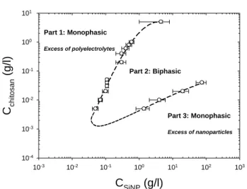
Fig. 2 Sequence of phase behaviours in the chitosan concentration-SiNP
65
concentration plane at T=20°C and fixed pH~4.5.
This section deals with the phase behaviour and the SANS experiments performed on charged SiNPs in the presence of oppositely charged chitosan semiflexible chains at fixed temperature T=20°C. At the constant pH chosen (see above), 4.5,
70
the silica particles undubiously carry a negative surface charge density (an estimate of the zeta potential from mobility -see ESI- corresponds to 25 negative effective charges).
In Figure 2, we have sketched the phase evolution of the samples with the chitosan concentration (vertical axis) and the
75
SiNPs concentration (horizontal axis) at equilibrium. For extremely low chitosan addition, the solutions are monophasic and transparent over the whole range of NPs concentration. When the chitosan concentration is increased, one observes for intermediate NPs concentrations a phase separation: a dilute
80
phase coexists with a more concentrated and viscous phase (see Part 2), while, at lower (Part 1) and higher (Part 3) NPs concentrations, the samples remain clear monophasic solutions. Such shape of the phase diagram reported in Figure 2 is reminiscent of “complex coacervation”51,52
due to electrostatic
85
attraction between polyelectrolytes and oppositely charged NPs or proteins.38-41,45-49,73 The two kinds of objects can first associate in primary complexes, which then are neutral. Above a certain concentration they precipitate in rich and poor liquid phases, or form fractal aggregates by controlled (diffusion limited or better
90
reaction limited) aggregation, or solid clusters (this depends on the form of the attraction potential).50 Another aspect is the release of the counterions of both species, which has an entropic contribution on the free energy, as predicted and experimentally observed.53 In practice for our system, SANS results indicate that 95
the concentrated lower phase contains the major part of the NPs
C
SiNP(g/l)
10-3 10-2 10-1 100 101 102 103C
c h it o s a n(g/l)
10-4 10-3 10-2 10-1 100 101 Part 2: Biphasic Part 1: Monophasic Excess of polyelectrolytes Part 3: Monophasic Excess of nanoparticlesq (Å
-1)
10-3 10-2 10-1M
WP(q) (
g/mo
l)
102 103 104 105 106 107 DataWormlike chain model
-2 -1 q2+10C chitosan 0.000 0.001 0.002 0.003 0.004 0.005 KC c hi tos an /R ( m ol/ g ) 0 2x10⁻⁶ 4x10⁻⁶ 6x10⁻⁶ 8x10⁻⁶
and of the chitosan, while the upper fluid phase is a very dilute solution of both NPs and chitosan. It is noteworthy that the phase separation is observed for minute quantities of chitosan.
5 10 15 20 25 30 35 40 45 50 55 60 65 70 75 80 85
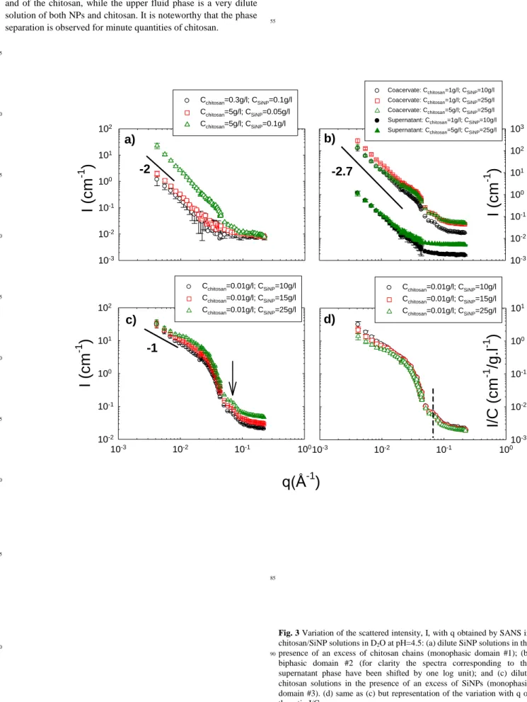
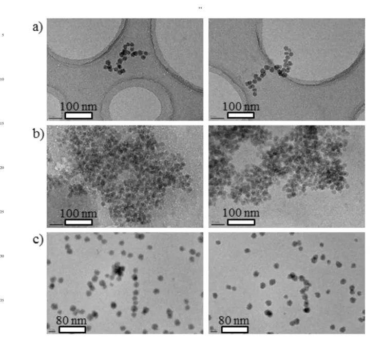
Fig. 3 Variation of the scattered intensity, I, with q obtained by SANS in
chitosan/SiNP solutions in D2O at pH=4.5: (a) dilute SiNP solutions in the
presence of an excess of chitosan chains (monophasic domain #1); (b)
90
biphasic domain #2 (for clarity the spectra corresponding to the supernatant phase have been shifted by one log unit); and (c) dilute chitosan solutions in the presence of an excess of SiNPs (monophasic domain #3). (d) same as (c) but representation of the variation with q of the ratio I/CSiNP.
95
I
(c
m
-1)
10-3 10-2 10-1 100 101 102 Cchitosan=0.3g/l; CSiNP=0.1g/l Cchitosan=5g/l; CSiNP=0.05g/l Cchitosan=5g/l; CSiNP=0.1g/l 10-3 10-2 10-1 100 101 102 103 Coacervate: Cchitosan=1g/l; CSiNP=10g/lCoacervate: Cchitosan=1g/l; CSiNP=25g/l
Coacervate: Cchitosan=5g/l; CSiNP=25g/l
Supernatant: Cchitosan=1g/l; CSiNP=10g/l
Supernatant: Cchitosan=5g/l; CSiNP=25g/l
q(Å
-1)
10-3 10-2 10-1 100I
(c
m
-1)
10-2 10-1 100 101 102 Cchitosan=0.01g/l; CSiNP=10g/l Cchitosan=0.01g/l; CSiNP=15g/l Cchitosan=0.01g/l; CSiNP=25g/l 10-3 10-2 10-1 10010 -3 10-2 10-1 100 101 Cchitosan=0.01g/l; CSiNP=10g/l Cchitosan=0.01g/l; CSiNP=15g/l Cchitosan=0.01g/l; CSiNP=25g/lI/
C
(c
m
-1/g.l
-1)
-1
-2
-2.7
I
(c
m
-1)
a)
b)
c)
d)
–00
To gain insight into the arrangement of the SiNPs and the local structure of the complexes, SANS experiments were performed on solutions characterizing the different parts of the phase diagram: Part 1 (excess of chitosan chains-monophasic domain), Part 2 (Biphasic domain) and Part 3 (excess of
SiNPS-5
monophasic domain). This is a powerful method for determining shapes of objects in solution over the range of 1-30 nm. Figure 3 shows the variations of the scattered intensity as a function of q measured for each of the representative solutions in heavy water and in the presence of 0.2 M CH3COONa and 0.3 M CH3COOH 10
at T=20°C. It is important to note that the SANS signal is dominated by the SiNPs, as expected from the high value of the SiNPs molecular volume (measurements in D2O/H2O mixture
eliminating the signal of chitosan by contrast matching, not shown here, corroborate this estimate).
15
Part 1: Figure 3a shows the SANS curves obtained for
Cchitosan=0.3 g/l / CSiNP=0.1; Cchitosan=5 g/l / CSiNP=0.05 and
Cchitosan=5 g/l / CSiNP=0.1 g/l monophasic mixtures (dilute
solutions of SiNPs in the presence of an excess of chitosan). The
20
scattering curve does not exhibit a Guinier regime with a plateau at low q associated to the finite size of the complexes but instead a ~ q-2 behaviour in a rather extended q range, followed by a high q oscillation. This q-2 dependence suggests a Gaussian distribution for the NPs inside the complexes, or branched
quasi-25
fractal aggregates. The global size of the complexes being larger than 30 nm.
Part 2: For this biphasic domain, the scattering varies as a q-α law with α ranging from 2.6 to 2.8, characteristic of rather compact fractal aggregates larger than 30 nm (the scattering
30
curves do not exhibit a Guinier regime with a plateau at low q). This behavior is observed in the whole biphasic domain for dense phases as well as for supernatant phases, as seen in Figure 3b. The power law is followed at large q, as for part 1, by a high q oscillation that will be discussed below.
35
Part 3: Figure 3c displays the scattering patterns for chitosan/SiNPs solutions at various SiNPs concentrations (Domain 3 of the phase diagram). The variations of the ratio I/CSiNP of the scattered intensity over the SiNP concentration are
illustrated in Figure 3d. The most interesting feature of Figure 3d
40
concerns the intermediate and high q-ranges where all the scattering curves superimpose on each other, thus indicating that the self-assemblies have the same structure at the spatial scale corresponding to these ranges. Furthermore in the lowest q-range, the q dependence of the scattered intensity tend to join for
45
the lowest concentrations, a power law with an exponent close to -1, which suggests a rod-like structure at the corresponding scale. This variation with q has never been observed in NP-polyelectrolyte complexes at our knowledge. The oscillation observed in the high q-range is the initial part of the oscillating
50
term of the shape dependent form factor of the particle cross-section.
In the low q range, the shape of the scattering curves depends on the NPs concentration. The system with a very large excess of SiNPs (CSiNP=25 g/l) tends to exhibit a Guinier regime with the 55
beginning of a plateau in the low q range associated with the average finite size of the scattered objects (here a mixture of rigid-rods and of free SiNPs). This “plateau” is followed by a
slight upturn probably associated to the presence of rods that dominate the signal at very low q. For SiNPs concentrations of 10
60
g/l and 15 g/l the curves show neither a Guinier plateau nor a significant upturn of the scattered intensity in the low q-range: the characteristic q-1 rod dependence is measured down to the lowest q, thus indicating that the rods dominating the SANS signal in this concentration domain are relatively long; i.e., larger than 30
65
nm.
All curves of Figure 3 exhibit an oscillation occurring at the same value of q for all the systems investigated. However, the absence of a Guinier regime at low q and the contribution of the incoherent background at high q prevented us from determining
70
the global and cross-sectional dimensions of the nanorod aggregates with very high accuracy. Therefore, it was interesting to turn to SAXS experiments at the ESRF high brilliance light source.
Nanorods SAXS characterization
75
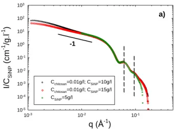
Figure 4a shows the variations of the ratio I/CSiNP of the scattered
intensity over the SiNP concentration versus the scattering wave vector q for nanorod solutions at two different NPs concentrations, CSiNP=10 g/l and 15 g/l. Due to the high mass and
concentration of the SiNPs, the SAXS signal is dominated by the
80
scattering of the NPs; the signal of chitosan chains is negligible. The scattering pattern of free SiNPs is also represented in the high q range in Figure 4a. The scattering curves of the complexes exhibit the same overall behaviour for both SiNP concentrations, characterized by the following sequence: a Guinier regime in the
85
low q range associated with the finite size and mass of the scattered objects, one intermediate regime in which the q dependence of the scattered intensity is described by a power law with an exponent close to -1, an axial Guinier regime at higher q corresponding to the size of the cross-section of the assemblies,
90
and finally well-defined oscillations associated to the shape-dependent form factor of the particle cross-section. The curve corresponding to the bare silica particles is also shown in Figure 4a. In the high q range, all the scattering curves (rod complexes and bare silica NPs) superimpose on each other, thus indicating
95
that rods have the same cross-section than that of free SiNPs.
q (Å
-1)
10-3 10-2 10-1I/C
S iN P(
c
m
-1/g
.l
-1)
10-5 10-4 10-3 10-2 10-1 100 101 102 103 Cchitosan=0.01g/l; CSiNP=10g/l Cchitosan=0.01g/l; CSiNP=15g/l CSiNP=5g/l -1 a)Fig. 4a Variation of the ratio I/CSiNP with q obtained using SAXS
experiments: comparison between free SiNPs (q>10-2 Å-1) and in the
presence of 0.01 g/l chitosan at T=20°C.
5
10
15
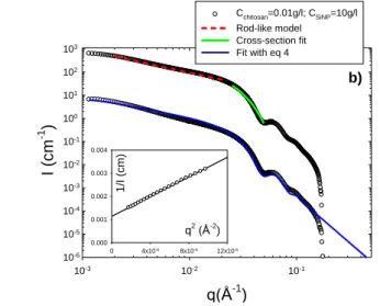
Fig. 4b SAXS spectra obtained for a 0.01 g/l chitosan/10 g/l SiNP
20
solution in 0.2 M CH3COONa and 0.3 M CH3COOH. Upper curve: the
dashed curve represents the fit of the data in the intermediate regime with a rod-like model, and the solid curve represents the fit of the high q data by a Guinier expression for the form factor of the section (see ESI). Bottom curve, for clarity the data have been shifted by two log units
25
along the y-axis: the continuous solid line represents the best fit of the data obtained by a combination of spheres and cylinders form factors (see eq 4). The inset shows the plot of 1/I versus q2 and the best linear fit to the
data.
Inner conformation
30
In the intermediate q regime, the scattering curves can be fitted satisfactorily by a rigid rod model. Figure 4b shows the fit realized for a 0.01 g/l chitosan/10 g/l SiNP solution, that is in the very dilute regime for chitosan, by means of the form factor derived for rigid rod particles, P(q)rod=π/qLc, where Lc is the 35
contour length.74 The high q data can be fitted by a Guinier expression for the form factor of the section (see ESI), giving the radius of gyration of the cross section, rc. By fitting the two
models above to the experimental data, after dividing by the contrast as for individual particles, one can determine the mass
40
per unit length of the rods, ML, the section, S, and the radius of
gyration, rc, of the cross section. From the fits of Figure 4b, we
obtain ML=(98±9)103 g/mol/nm, S=131±15 nm2, and rc=6±0.2
nm. If the rods consist of straight SiNPs monolayer wires, then the mass per unit length can be calculated to be
45
~(mass/diameter)SiNP=3106/24=125103 g/mol/nm, a value
slighly larger than the experimental determination. This discrepancy may be explained by the contribution of free NPs to the SAXS signal (see next part).
The radius of gyration of the cross-section of such a nanorod is
50
given by rc2=R2/2. Using the experimental value of rc=6 nm, one
obtains R=8.5 nm, which is a value in good agreement with the experimental one determined for bare silica particles (see Figure SI-6 in the ESI). In all cases, the determined local structural parameters are consistent with a well-ordered single-strand 1D
55
SiNP self-assembly whose cross-section is that of a single SiNP. This is corroborated by the oscillations observed at higher q that
are identical for all the samples for q>410-2 Å-1 (when S(q)~1) and that are reasonably well reproduced with P(q) calculated for the spherical SiNPs with a radius R of 9.2 nm (see Figure 4 and
60
ESI ).
Overall shape of the nanorods
The low q data have been fitted by the classical Guinier expression, 1/I(q)=1/I(0)(1+q2R2G/3), which provides the
65
average radius of gyration, RG, and the zero-wave vector
intensity, I(0), associated to the weight-average molecular weight, MW, of the rods. For rodlike particles with large aspect ratio
(Lc<<Lp), R2G=L2/12, where L is the average contour length of
the rod. For CSiNP=10g/l, we obtain RG=77 nm, L=267 nm and 70
MW=(31±3)10 6
g/mol. Inspection of the data calls for two remarks. First, the objects formed behave as rigid rods, as shown by the comparison between the calculated value L=121/2R
G=267
nm and the experimental value of MW/ML=(3110
6
)/(98103)=316 nm (ML is the silica mass per 75
unit length of the rodlike object). Secondly, the average number of SiNPs constituting a nanorod is, neglecting the Virial effects, ~MW,nanorod/MW,SiNP~11 (or ~14-15 if one considers the ratio
between the rod length and the NPs diameter, equal to 267/18.4). For Cchitosan=0.01 g/l/CSiNP=15 g/l solutions, the zero-wave 80
vector scattered intensity, I(0), is slightly lower due to the enhanced contribution to the signal of the free SiNPs, and thus showing that the proportion of both populations has to be taken into account: free SiNPs and rodlike self-assemblies (see part 3.4.). The low-q signal is, however, still dominated by the rodlike
85
behaviour.
Polyelectrolyte Concentration Influence on the
Shape of the NPs Self-Assemblies
To gain insight into the shape of the NPs self-assemblies, complementary cryo-TEM experiments were performed on
90
solutions characterizing the three parts of the phase diagram, using also cryo-TEM as a support for the discussion.
Part 1, excess of chitosan:
Evidence in favour of dilute randomly self-assembled NPs
95
structures of 300-400 nm, as already suggested by the q-2
dependence observed in the SANS spectra was provided by cryo-TEM images of solutions containing an excess of chitosan (5 g/l) and 0.1 g/l SiNPs (Figures 5a). A common observation in these micrographs is that NPs do not form single-strand structures but
100
instead form flexible branched structures with variable lengths, cross-sections, and aggregation numbers (mostly between 20 and 50). Thus an apparent fractal dimension of 2 is in agreement with such branched or contorted structure. Also, no free NPs are observed. Thus, assuming that all chitosan chains are involved in
105
the self-assemblies, we can estimate that the number of chains per complex is around 16 ~ (Number of chitosan chains)/(Number of NPs<Nagg>), with <Nagg>~30 the average NPs aggregation
number.
110
Part 2, biphasic domain:
Figures 5b show micrographs of vitrified coacervate phases (concentrated viscous phases). Here, we see dense and globular SiNP aggregates larger than 500 nm composed of most of the
q(Å-1 ) 10-3 10-2 10-1 I (cm -1 ) 10-6 10-5 10-4 10-3 10-2 10-1 100 101 102 103 Cchitosan=0.01g/l; CSiNP=10g/l Rod-like model Cross-section fit Fit with eq 4 q2 (Å-2 ) 0 4x10⁻⁶ 8x10⁻⁶ 12x10-6 1/ I (cm) 0.000 0.001 0.002 0.003 0.004 b)
–00
NPs and chitosan chains. These observations corroborate the SANS analysis.
Part 3, excess of SiNPs:
Imaging of chitosan/SiNP solutions using Cryo-TEM
5
corroborates the SANS and SAXS results indicating the presence of straight rodlike structures in monophasic solution with large excess of NPs. Figure 5c show representative images that clearly demonstrate the presence of aligned nanorod-like objects. Some objects (see right hand picture of Figure 5c) present some kinks
10
probably due to a collapse of the rod structure due to ice melting under beam irradiation. Thus for the structure of the objects in bulk solution we better rely on the SAXS, which definitely shows rodlike behaviour. All the rods exhibit uniform diameters of approximately 20 nm, which are in agreement with the diameters
15
calculated from rc values determined from SAXS data (assuming
a circular cross-section). Beyond agreement with SANS/SAXS, TEM gives new information on the rods lengths, which are variable (mostly between 160 and 280 nm). In the light of invariant diameters, and in the absence of branched structures, the
20
observed nanorods are thought to correspond to single strand rigid NP assemblies as already shown by the scattering analysis and the experimental value of the linear mass density.
The low electronic contrast of the biopolymer does not enable to identify the number of chain per complex and their
25
arrangement in the nanorods structure. Higher resolution, Cs corrected and energy filtered TEM would be necessary to reveal that information. To shed some light on this aspect, we have estimated the amount of chitosan per complexes from SAXS measurements. This simple calculation have been made on the
30
basis of the average number of individual nanoparticles and of the nanorods determined by fitting the scattering pattern by the following equation:75 ) ( ) ( ) (q I q I q I rods spheres , (4)
where Irods(q) and Ispheres(q) are the scattered intensities related 35
respectively to the form factor of the rods and of the spheres (see ESI for equations). For the rods, we used the classical form factor derived for cylinders (see ESI). The best agreement with the data presented in Figure 4b is obtained for spheres=4.310
-3
,
rods=2.310-4, Rspheres=Rcylinders=8.5 nm, =0.11, and for 40
Lcylinders=250 nm (see bottom curve of Figure 4b, fit realized with
eqs 2, 3 and 4 using the SASfit program76). Then, considering that SiNPs are in excess and that, according to cryo-TEM, only SiNPs present in complexes display the ribbed texture attributed to chitosan chain binding, one can hypothesize that all the
45
chitosan chains are involved in the complexes. Finally, one derives an average concentration of 1.8 chains of chitosan per nanorods. This result first shows that very few chains are needed to allow SiNPs organisation into nanorods. A second striking point is that the average contour length of the biopolymers (~ 943
50
nm) is significantly higher than the average nanorods length (~250 nm) suggesting that chitosan chains are somehow wrapped around SiNPs. This could be permitted by adequacy between the NPs surface curvature and the chitosan chains bending, controlled by its persistence length. This is possible since Lp (7.5 nm) ~ R 55
(8.5 nm). The number of NPs is 250 nm/(8.5x2) = 14.7, corresponding to a chain length of 62 nm per NPs, i.e. slightly
more than one NP circumference (53 nm).
This suggests that the chain wrapping around the SiNP is somehow helical, and thus adds rigidity explaining the single
60
strand rod-like structure. This is in striking contrast with DNA packaging into chromatin, where an almost rigid polymer with bare persistence length Lp about 50 nm is compacted around
small oppositely charged histones with R ≈ 3.5 nm.77 Here a
much more flexible polymer (intrinsic persistence length Lp ≈ 7.5 65
nm) can be rigidified, only via electrostatic interactions, into rod-like structure by nanoparticles with radius such as Lp/R ≈ 1.
The average length of these 1D assemblies (250 nm) gives a lower bound for the nanorods persistence length, Lp,rod,min, and
can thus be used to estimate the Young modulus, E, of such rods.
70
Indeed, in the case of a rigid and uniform rod E=4Bs/πR 4
, where Bs is the bending stiffness and R the radius of the section.78,79 A
lower bound for the modulus of such nanorods can be estimated: Emin=(Lp,rod,minkT4)/(πR 4 )=1.79×10⁵ Pa. 75 80 85 90 95 100 105 110 115
5 10 15 20 25 30 35 40 45
Fig. 5 Cryo-TEM images of a) a vitrified Cchitosan=5g/l / CSiNP=0.1g/l
monophasic solution (Part 1) ; b) a coacervate phase with initial concentrations of Cchitosan=1g/l and CSiNP=10g/l (Part 2); and c) a
Cchitosan=0.01g/l / CSiNP=10g/l monophasic solution (Part 3) in the presence
of 0.3 M CH3COOH and 0.2 M CH3COONa. 50 55 60 65 70 75 80 85 90 95 100 105 110
–00
Influence of the ratio L
p/R
As seen in the previous part, it is possible to obtain well-defined 1D rodlike self-assemblies of SiNPs in the presence of an excess of NPs. This suggests a role of the polyelectrolyte rigidity, and
5
the importance of using less rigid PELs. Therefore the polyelectrolyte poly-L-lysine (PLL), displaying -like chitosane- positive charges along its flexible backbone, was chosen; the second partner, 10 nm SiNPs, remained unchanged. The concentration of KBr was fixed to 0.2 M (PLL being purchased
10
with Br- counterions, excess salt KBr was chosen) in order to keep the same ionic strength than in the chitosan-SiNPs systems in the presence of 0.2 M CH3COONa. Within these experimental
conditions, Lp(PLL)~1 nm (PLL intrinsic persistence length), and
Lp/R, is close to 0.1. 15
As for the chitosan-SiNPs system, the mixed solutions are monophasic and transparent in the presence of an excess of PLL (domain 1), or of SiNPs (domain 3). A biphasic (domain 2) is observed in the intermediate range of concentrations (with boundaries pretty close to those determined previously with
20
chitosan), where one rich phase of white coacervate coexists with an upper dilute and limpid phase. To investigate the effect of, Lp/R on the structure of the complexes and on the formation of
nanorods, SANS experiments were performed on two PLL/SiNPs solutions in the presence of an excess of NPs (domain 3). The
25
ratio between the concentration of PLL and SiNPs is identical for both samples and is the same as that used for characterizing the complexes of SiNPs with semi-rigid chitosan in the same domain #3. Both representative samples appear visually as a unique phase but are opalescent and were stable on an observation time scale of
30
several months.
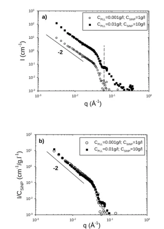
The scattering patterns obtained for CPLL=0.01 g/l /
CSiNP=10, and CPLL=0.001 g/l / CSiNP=1 and showed in Figure 6
do not exhibit any Guinier regime with a plateau at low q associated to the finite size of the complexes but instead a q-2 35
regime behavior in an extended q range, followed by the first oscillation associated to the form factor of the cross-section of the 10 nm radius SiNPs. The variations of the ratio I/CSiNP of the
scattered intensity over SiNP concentration are illustrated in Figure 6b. A first mostly interesting feature is that the scattering
40
curves superimpose on each other in the whole q-range indicating that the complexes, which are larger than 30 nm, have the same structure. This suggests that the latter depends only on Lp/R in
this domain. A second is the low q slope (q-2 dependence) suggesting either a Gaussian distribution for the SiNPs inside the
45
complexes, or branched aggregates. We have here an important result, because it profoundly differs from that obtained with the semiflexible polyelectrolyte chitosan (which showed a q-1 law due to the formation of nanorods within the same experimental conditions). This suggests the major role played by the
50
polyelectrolyte persistence length. Here, PLL, a flexible polyelectrolyte, with Lp/R~0.1, does not induce the formation of
1D structures. 55 60 65 70 75 80 85 90
Fig. 6 (a) SANS spectra obtained for Poly-L-lysine (PLL)/SiNP solutions
in domain #3 (excess of NPs) in the presence of 0.2 M KBr. (b) same as (a) but representation of the variation with q of the ratio I/CSiNP.
95
The results, summarized in the “general phase diagram” (see Figure 7), point for the first time the role of the characteristic ratio Lp/R in the control of the structure, making plausible a
cognitive generalization to many other candidate species.
100 105 110 115 120
C
SiNP(g/l)
10-3 10-2 10-1 100 101 102 103C
p o ly e le c tro ly te(g/l)
10-4 10-3 10-2 10-1 100 101 Part 1: Monophasic P(q)~q-2 Part 2: Biphasic P(q)~q-2.7 Part 3: Monophasic P(q)~q-1 Lp/R=1 Lp/R=0.1 q (Å-1 ) 10-3 10-2 10-1 100 I (c m -1 ) 10-3 10-2 10-1 100 101 102 103 CPLL=0.001g/l; CSiNP=1g/l CPLL=0.01g/l; CSiNP=10g/l a) -2 q (Å-1 ) 10-3 10-2 10-1 100 I/C S iN P (cm -1 /g. l -1 ) 10-3 10-2 10-1 100 101 102 CPLL=0.001g/l; CSiNP=1g/l CPLL=0.01g/l; CSiNP=10g/l b) -2Fig. 7 Sequence of phase behaviours in the Chitosane
polyelectrolyte concentration - SiNP concentration plane in the presence of an excess of salt. The form factor, P(q), scales as ~q
-2
, ~q-2.7, and q-1 respectively in part 1, 2, and 3 of the phase diagram for Lp/R~1. A flexible polyelectrolyte (PLL), with 5
Lp/R=0.1, does not induce the formation of nanorods in domain
#3.
Conclusions
This work can be commented from different points of view. First, it can be seen as an exploration of the different structures
10
obtained in the phase diagram resulting from an associative mechanism, here involving electrostatic complexation, and in given concentrations range, leading to phase separation, the so-called “complex coacervation”. The specificities of three kinds of structure are clearly cut thanks to the combination of SANS,
15
SAXS, and cryo-TEM for the three phase diagram regions. From these structures in the three regions of the phase diagram, we can try to imagine the mechanisms for a system of chains and particles with possibly strong interactions since all particles are multiply charged and all chain segments are charged.
20
The obtained shapes are summarized in Figure 7. When chains are in excess, branched objects are formed made of linear short strands, while when NPs are in excess linear objects appear. In the stoichiometric range, which corresponds to the biphasic regime, more quasi-3d compact objects are formed. They are
25
observed both in the supernatant and in the coacervate (dense) phase (the fractal dimension determined by SANS is the same in both phases). This suggests that the dense objects are formed prior to phase separation. Their shape would be induced by the high number of particles per monomer in the stoichiometric
30
complexes, while more expanded shapes correspond to an insufficient number of NPs (part 1) or to an insufficient number of chains (part 3). In parts 1 and 3 as well as in the supernatant phase (part 2), it is very likely that individual complexes are formed. From this first point of view, it seems that the shapes of
35
the complexes are dictated by the monomer/NP ratio.
Second, the succession of different NPs organisations is not observed with such consistency in most of the former works, and in particular, rodlike shapes as well defined as here - as seen at the light of SAXS measurements- are rarely observed. Our result
40
is due first to the use of a semiflexible polyelectrolyte, and second to a good adequacy between persistence length and NPs radius. Thus a second important ratio appears to be Lp/R. Indeed,
these results show the major role played by the polyelectrolyte persistence length. In particular, the flexible polyelectrolyte
45
which we have used, poly-L-lysine, with Lp/R~0.1, does not
induce the formation of 1D structures. We point here that the ratio Lp/R plays a pivotal role in the formation of 1D structures.
Finally the structure of the chain itself may play a role: the chitosan chain possesses gentle helical shape, which can help a
50
lot to make the structure more rigid. The helix could wrap gently the NPs. This rejoins some pictures and evaluation formerly proposed by theorists.38 However, while this was proposed for the interaction between one chain and one NP, this is observed here in the case of complexes involving several NPs per chain, where
55
the structure formed renders easy a precise check. The use of a natural polyelectrolyte polysaccharide involving such helical
structure appears to be a good choice, although the chain anchorages at the surface of the NPs are not as specific as they could be for proteins.80,81
60
Acknowledgments
This work was supported by a doctoral fellowship from the CNRS and the CEA (L. S.). The authors thank the Laboratoire Léon Brillouin (LLB, CEA Saclay, France), the Institut Laue-Langevin (ILL, Grenoble, France), and the European Synchrotron
65
Radiation Facility (ESRF, Grenoble) for beam time allocations. We wish to thank J. Gummel and I. Grillo for their help during the SAXS and the SANS experiments, respectively.
Notes and references
a Laboratoire Matière et Systèmes Complexes (MSC), UMR CNRS 7057, 70
Université Paris Diderot-Paris 7, Bâtiment Condorcet, 10 rue Alice Domon et Léonie Duquet, 75205 Paris cedex 13, France. E-mail : [email protected], Fax : 33 1 5727 6211, Tel : 33 1 5727 6139
b Laboratoire Léon Brillouin, UMR 12 CEA-CNRS, CEA Saclay, 91191 75
Gif-sur-Yvette, France.
c Laboratoire Chimie de la Matière Condensée de Paris, UMR 7574,
UPMC, Collège de France, 11 place Marcelin Berthelot, 75005 Paris, France.
80
† Electronic supplementary information (ESI) available: Scattering methods, single solute solutions characterization, and models. See DOI:
10.1039/……
85
1. R. Bhattacharya, C. Ranjan Patra, S. Wang, L. Lu, M. J. Yaszemski, D. Mukhopadhyay, P. Mukherjee, Adv. Func. Mater., 2006, 16, 395-400.
2. P. L. Anelli, N. Spencer, J. F. Stoddart, J. Am. Chem. Soc., 1991, 113, 5131.
90
3. J. Otsuki, M. Tsujino, T. Iizaki, K. Araki, M. Seno, K. Takatera, T. Watanabe, J. Am. Chem. Soc., 1997, 119, 7895.
4. A. P. de Silva, H. Q. N. Gunaratne, C. P. McCoy, J. Am. Chem. Soc., 1997, 119, 7891.
5. M. Grzelczak, J. Vermant, E. M. Furst, L. M. Liz-Marza, ACS Nano,
95
2010, 4, 3591-3605.
6. Z. Nie, A. Petukhova, E. Kumacheva, Nat. Nanotechnol., 2010, 5, 15. 7. S. C. Glotzer, M. A. Horsch, C. R. Iacovella, Z. Zhang, E. R. Chan, X.
Zhang, Curr. Opin. Colloid Interface Sci., 2005, 10, 287. 8. S. C. Glotzer, M. J. Solomon, Nat. Mater., 2007, 6, 557.
100
9. G. A. DeVries, M. Brunnbauer, Y. Hu, A. M. Jackson, B. Long, B. T. Neltner, O. Uzun, B. H. Wunsch, F. Stellacci, Science, 2007, 315, 358.
10. W. U. Huynh, J. J. Dittmer, A. P. Alivisatos, Science, 2002, 295, 2425.
105
11. M. Rycenga, J. M. McLellan, Y. Xia, Adv. Mater., 2008, 20, 2416. 12. Z. Tang, N. A. Kotov, M. Giersing, Science, 2002, 297, 237. 13. A. Courty, A. Mermet, P. A. Albouy, E. Duval, M. P. Pileni, Nat.
Mater., 2005, 4, 395.
14. D. Zerrouki, J. Baudry, D. Pine, P. Chaikin, J. Bibette, Nature, 2008,
110
455, 380.
15. Z. Nie, D. Fava, E. Kumacheva, S. Zou, G. C. Walker, M. Rubinstein,
Nat. Mater., 2007, 6, 609.
16. S. A. Maier, P. G. Kik, H. A. Atwater, S. Meltzer, E. Harel, B. E. Koel, A. A. G. Requicha, Nat. Mater., 2003, 2, 229.
115
17. S. A. Maier, M. L. Brongersma, P. G. Kik, S. Meltzer, A. A. G. Requicha, H. A. Atwater, Adv. Mater., 2001, 13, 1501.
18. W. Nomura, M. Ohtsu, T. Yatsui, Appl. Phys. Lett., 2005, 86, 181108. 19. C.-J. Wang, L. Huang, B. A. Parviz, L. Y. Lin, Nano Lett., 2006, 6,
2549.
–00
20. T. Yatsui, Y. Ryu, T. Morishima, W. Nomura, T. Kawazoe, T. Yonezouva, M. Washizu, H. Fujita, M. Ohtsu, Appl. Phys. Lett., 2010, 96, 133106.
21. J. N. Anker, W. Paige Hall, O. Lyandres, N. C. Shah, J. Zhao, R. P. Van Duyne, Nat. Mater., 2008, 7, 442.
5
22. G. Kawamura, Y. Yang, M. Nogami, Appl.Phys. Lett., 2007, 90, 261908.
23. T. C. Deivaraj, N. L. Lala, J. Y. Lee, J. Colloid and Interface Sci., 2005, 289, 402.
24. V. M. Cepak, C. R. Martin, J. Phys. Chem. B, 1998, 102, 9985.
10
25. M. H. Huang, A. Choudrey, P. Yang, Chem. Comm., 2000, 12, 1063. 26. C. J. Murphy, N. R. Jana, Adv. Mater., 2002, 14, 80.
27. N. Toshima, Y. Wang, Chem. Lett., 1993, 1611.
28. M. Cao, Y. Wang, C. Guo, Y. Qi, C. Hu, E. Wang, J. Nanosci.
Nanotech., 2004, 4, 824.
15
29. B. Wiley, Y. Sun, B. Mayers, Y. Xia, Chem. Eur. J., 2005, 11, 454. 30. T. Harada, H. Fujiwara, Journal of Physics: Conference Series, 2007,
61, 394-398.
31. M. E. Leunissen, R. Dreyfus, F. C. Cheong, D. G. Grier, R. Sha, N. C. Seeman, P. M. Chaikin, Nat. Mater., 2009, 8, 590.
20
32. K.K. Caswell, J. N. Wilson, U. H. F. Bunz, C. J. Murphy, J. Am.
Chem. Soc., 2003, 125, 13914.
33. K. D. Hermanson, S. O. Lumsdon, J. P. Williams, E. W. Kaler, O. D. Velev, Science, 2001, 294, 1082.
34. C. Ribeiro, E. J. H. Lee, E. Longo, E. R. Leite, ChemPhysChem,
25
2006, 7, 664.
35. S. Shanbhag, Z. Tang, N. A. Kotov, ACS Nano, 2007, 1, 126. 36. K. Liu, Z. Nie, N. Zhao, W. Li, M. Rubinstein, E. Kumacheva,
Science, 2010, 329, 197-200.
37. Z. Nie, D. Fava, M. A. Winnik, M. Rubinstein, E. Kumacheva, J. Am.
30
Chem. Soc., 2008, 130, 3683.
38. C. Holm, J. F. Joanny, K. Kremer, R. R. Netz, P. Reineker, T. Vilgis, R. Winkler, Adv. Polym. Sci., 2004, 166, 67.
39. F. Cousin, J. Gummel, D. Ung, F. Boué, Langmuir, 2005, 21, 9675. 40. Jonghoon Lee, Yuri O. Popov, and Glenn H. Fredrickson, J. Chem.
35
Phys., 2008, 128, 224908.
41. G. Nizri, A. Makarsky, S. Magdassi and Y. Talmon, Langmuir, 2009,
25, 1980-1985.
42. A. Y. Grosberg, T. T. Nguyen, B. I. Shklovskii, Rev. Mod. Phys., 2002, 74, 329.
40
43. T. T. Nguyen and B. I. Shklovskii, J. Chem. Phys., 2001, 114, 13. 44. C. Y. Kong and M. Muthukumar, J. Chem. Phys., 1998, 109,
1522-1527.
45. M. Jonsson, P. Linse, J. Chem. Phys., 2001, 115, 10975.
46. K. Keren, Y. Soen, G. Ben Yoseph, R. Gilad, E. Braun, U. Sivan, Y.
45
Talmon, Phys. Rev. Lett., 2002, 89, 088103.
47. (a) J. Gummel, F. Boué, D. Clemens, F. Cousin, Soft Matter, 2008, 4, 1653–1664. (b) J. Gummel, F. Boué, B. Demé, F. Cousin, Journal of
Physical Chemistry B, 2006, 110 (49), 24837 – 24846.
48. C. L. Cooper, A. Goulding, A. Basak Kayitmazer, S. Ulrich, S. Stoll,
50
S. Turksen, S. Yusa, A. Kumar, P. L. Dubin, Biomacromolecules, 2006, 7, 1025-1035.
49. A. Basak Kayitmazer, S. P. Strand, C. Tribet, W. Jaeger, P. L. Dubin,
Biomacromolecules, 2007, 8, 3569.
50. F. Cousin, J. Gummel, S. Combet, F. Boué, Adv. Col. Int. Sci.,
55
2011, 167, 71-84.
51. C. G. De Kruif, F. Weinbreck, R. De Vries, Curr. Opin. Coll.
Interface Sci, 2004, 9, 340.
52. H. G. Bungenberg de Jong, H. R. Kruyt, Proc. K. Ned. Akad. Wet., 1929, 32, 849.
60
53. J. Gummel, F. Cousin, F. Boué, J. Am. Chem. Soc., 2007, 129, 5806-5807.
54. B. Bharti, J. Meissner, G. H. Findenegg, Langmuir, 2011, 27, 9823-9833.
55. E. Buhler, O. Guetta, M. Rinaudo, Int. J. Polym. Anal. and Charac.,
65
2000, 6, 155.
56. E. Buhler, M. Rinaudo, Macromolecules, 2000, 33, 2098-2106. 57. C. Esquenet, E. Buhler, Macromolecules, 2001, 34, 5287.
58. C. Esquenet, P. Terech, F. Boué, E. Buhler, Langmuir, 2004, 20, 3583-3592.
70
59. M. Rasmusson, S. Wall, Colloid Surf. A, 1997, 122, 169–181.
60. P. Van der Meeren, H. Saveyn, S. Bogale Kassa, W. Doyen, R. Leysen, Phys. Chem. Chem. Phys., 2004, 6, 1408–1412 .
61. D.F. Evans, H. Wennerström, The Colloidal Domain; Wiley-VCH: NewYork, 1994.
75
62. J. Appell, G. Porte, E. Buhler, J. Phys. Chem. B, 2005, 109, 13186-13194.
63. K. S. Schmitz, An Introduction to Dynamic Light Scattering by
Macromolecules; Academic Press: London, 1990.
64. C. Esquenet, E. Buhler, Macromolecules, 2002, 35, 3708-3716.
80
65. D. E. Koppel, J. Chem. Phys., 1972, 57, 4814. 66. S. W. Provencher, Makromol. Chem., 1985, 82, 632.
67. R. Ravindra, K. R. Krowidi, A. A. Kahn, Carbohydrate Polymers, 1998, 36, 121-127.
68. J. S. Pedersen, P. Schurtenberger, Macromolecules, 1996, 29, 7602.
85
69. W. Burchard, K. Kajiwara, Proc. R. Soc. London, Ser. A, 1970, 316, 185.
70. P. Sharp, V. A. Bloomfield, Biopolymers, 1968, 6, 1201. 71. E. Buhler, F. Boué, Eur. Phys. J. E, 2003, 10, 89. 72. E. Buhler, F. Boué, Macromolecules, 2004, 37, 1600-1610.
90
73. (a) E. Buhler, J. Appell, G. Porte, J. Phys. Chem. B, 2006, 110, 6415-6422. (b) F. Carn, N. Steunou, M. Djabourov, T. Coradin, F. Ribot, J. Livage, Soft Matter, 2008, 4, 735-738. (c) F. Carn, O. Durupthy, B. Fayolle, T. Coradin, G. Mosser, M. Schmutz, J. Maquet, J. Livage, N. Steunou, Chem. Mater., 2010, 22, 398–408. (d) F. Carn, F. Boué, M.
95
Djabourov, N. Steunou, T. Coradin, J. Livage, S. Floquet, E. Cadot, E. Buhler, Soft Matter 2012, 8, 2930-2944.
74. (a) J. des Cloizeaux, Macromolecules, 1973, 6, 403. (b) S. Ulrich, E. Buhler, J.-M. Lehn, New J. Chem., 2009, 33, 271-292.
75. N. Jouault, R. Nguyen, M. Rawiso, N. Giuseppone, E. Buhler, Soft
100
Matter 2011, 7, 4787.
76. SASfit at: http://kur.web.psi.ch/
77. A. A. Zinchenko, K. Yoshikawa, D. Baigl, Phys. Rev. Lett., 2005, 95, 228101.
78. L. Shi, F. Carn, F. Boué, E. Buhler, ACS Macro Lett., 2012, 1,
857-105
861.
79. K. S. Bloom, Chromosoma, 2008, 117, 103.
80. I. Morfin, E. Buhler, F. Cousin, I. Grillo, F. Boué,
Biomacromolecules, 2011, 12, 859.
81. Y. Ruff, E. Buhler, S. J. Candau, E. Kesselman, Y. Talmon, J. M.
110