HAL Id: hal-01627692
https://hal.archives-ouvertes.fr/hal-01627692
Submitted on 2 Nov 2017
HAL is a multi-disciplinary open access
archive for the deposit and dissemination of
sci-entific research documents, whether they are
pub-lished or not. The documents may come from
teaching and research institutions in France or
abroad, or from public or private research centers.
L’archive ouverte pluridisciplinaire HAL, est
destinée au dépôt et à la diffusion de documents
scientifiques de niveau recherche, publiés ou non,
émanant des établissements d’enseignement et de
recherche français ou étrangers, des laboratoires
publics ou privés.
Dense mapping for monocular-SLAM
Abiel Aguilar-González, Miguel Arias-Estrada
To cite this version:
Abiel Aguilar-González, Miguel Arias-Estrada. Dense mapping for monocular-SLAM. 2016
Interna-tional Conference on Indoor Positioning and Indoor Navigation (IPIN), Oct 2016, Alcala de Henares,
Spain. pp.1 - 8, �10.1109/IPIN.2016.7743671�. �hal-01627692�
Dense mapping for monocular-SLAM
Abiel Aguilar-Gonz´alez and Miguel Arias-Estrada
Reconfigurable computing laboratory, Computer science department Instituto Nacional de Astrof´ısica, ´Optica y Electr´onica (INAOE) Luis Enrique Erro # 1, Tonantzintla, Puebla, Mexico C.P. 72840
Email: {abiel,ariasmo}@inaoep.mx
Abstract—Simultaneous Localization and Mapping (SLAM) is the problem of constructing a 3D map while simultaneously keep-ing track of an agent location within the map. In recent years, work has focused in systems that use a single camera as the only sensing mechanism (monocular-SLAM). 3D reconstruction (map) by monocular-SLAM systems is a point cloud where all points preserve high accuracy and can deliver visual environmental in-formation. However, the maximum number of points in the cloud is limited by the tracked features, this is named “sparse cloud problem”. In this work, we propose a new SLAM framework that is robust enough for indoor/outdoor SLAM applications, and at the same time increases the 3D map density. The point cloud density is increased by applying a new feature-tracking/dense-tracking algorithm in the SLAM formulation. In order to achieve real-time processing, the algorithm is formulated to facilitate a parallel FPGA implementation. Preliminary results show that it is possible to obtain dense mapping (superior to previous work) and accurate camera pose estimation (localization) under several real-world conditions.
I. INTRODUCTION
Simultaneous Localization and Mapping (SLAM) is the problem of constructing a map with respect to an unknown environment while simultaneously keeping track of an agent location within the map. This is used in several applica-tions such as, self-driving cars, unmanned aerial vehicles, autonomous underwater vehicles, planetary rovers and domes-tic robots [1–3]. In order to develop a SLAM solution, it is necessary to have sensors that observe the environment and if it is possible, sensors that provide information about the trajectory. There are several sensors available for this purpose (odometers, gyrometers, laser rangefinders, cameras, sonars, etc.). In recent years, work has focused in systems that use cameras as the only sensing mechanism (visual-SLAM). This choice was motivated because nowadays, it is possible to find inexpensive, small and light commercial cameras and they provide visual environmental information that can be exploited to create appearance-based descriptions of the map components [4]. In most current state of the art, the use of a single camera (monocular-SLAM) instead of binocular/trinocular configurations is the most popular and an active research field [5–7]. This is because a single camera avoids addressing the multiple cameras synchronization, in-terpretation of the different responses of each image sensor to color and luminance, and mechanical alignment between cameras.
A. Monocular-SLAM
The idea of using a single camera has become popular since the emergence of the single camera SLAM or MonoSLAM [8]. This is due to wide availability of single cameras than a stereo pair, through cell phones, personal digital assistants or personal computers. The monocular approach offers a simple, flexible and economic solution in terms of hardware demand and processing time but present the partially observable problem. The partially observable problem exists where the camera does not provide sufficient information from a simple observation to determine the depth of a point. i.e., a feature-tracking across two or more different viewpoints has to be performed. Then, it is possible to obtain tridimensional information from a single camera only when there is an appropriate separation between the viewpoints.
Several contributions in monocular-SLAM have been re-ported in the literature [5–7], however, there are still many problems such as, low performance under dynamic scenes or sparse point clouds. Most monocular-SLAM systems fail due to accumulated errors while the environment is being explored. These cumulative errors produce inconsistent camera pose estimation and incongruous maps. In general, there are three main problems in the current state of the art: 1. It is assumed that camera movement is smooth and that there will be consistency in the appearance of feature points but in general, this is not true. This assumption is related to the feature extractor and feature-tracking algorithm used in the SLAM formulation. This originates an inaccuracy in the camera pose when it captures images with low texture or that are blurred due to rapid movements of the sensor. 2. Most of researchers assume that the explored environment is static and that they only contain stationary and rigid elements; the majority of environments contain people and objects in motion. If this is not considered, the moving elements will originate false matches and consequently generate unpredictable errors in all the system. 3. The world is visually repetitive. There are several similar textures, such as the architectural elements, foliage and walls of brick or stone. This makes it difficult to track features because there are several similar points that introduce false matches. To solve this inconvenience, typically, only the most dominant features are tracked. Unfortunately, this generates the sparse cloud problem that limits the 3D en-vironmental understanding and makes difficult the recognition of objects or places.
B. The sparse cloud problem
Traditional monocular-SLAM systems extract feature points by applying any type of feature extractor [9]. There are several feature extraction algorithms in the literature (Harris [10], FAST [11], SUSAN [12], Shi-Tomasi [13], etc.); however, in all cases the maximal number of features that can be extracted varies between 0.5% and 4.0% of all points in the image, depending on the selected algorithm and its particular configuration. In practice, traditional monocular-SLAM sys-tems work with configurations that allow extracting near 1% of the points from an image [9]. This limits the real-world applications performance since only 1% of the image points is used to obtain the 3D information, thus, the visual en-vironmental understanding, high-level descriptors application and objects/structures recognition in the point cloud have low stability under real-world scenarios. Even the most current and popular monocular-SLAM systems, for example ORB-SLAM [14] or LSD-SLAM [15] are limited to sparse point clouds.
C. Motivation and scope
The sparse point cloud problem limits the spatial resolution, and therefore, the level of detail in the 3D map. Several SLAM applications such as, automatic car piloting [16], rescue tasks for high-risk environments [1] and planetary exploration [2] have difficulties to use the map generated by the monocular-SLAM systems as 3D reference. Typically, 3D reconstruction algorithms carry out the 3D map estimation [17]. In recent years, the increase of computing power and a better SLAM algorithms understanding, allowed to increase the point clouds density. In some works, several visual-feature types are bundled in a SLAM framework that increases the cloud density. Other trend that enables semi-dense reconstructions consist in camera localization by optimizing directly over image pixel intensities. Unfortunately, in all cases, the proposed solutions only allow semi-dense point clouds and the performance over untextured regions is low. Furthermore, to reach real-time processing, only low-resolution images are supported. In this work, we are interested in how to increase the density of the monocular-SLAM systems based on RGB cameras. Any RGB-based monocular-SLAM that provides dense mapping would offer full 3D environmental understanding and simplify the high-level descriptors application and objects/structures recognition within the map. In addition, RGB-based monocular-SLAM systems can work correctly under indoor/outdoor environments. Finally, a sparse cloud problem solution would enable the use of monocular-SLAM under several outdoor applications such as, augmented reality [3] or 3D reconstruction [18]. In the current state of the art, the sparse cloud problem is addressed with RGB-based monocular-SLAM approaches. Unfortunately, these approaches are limited to indoor applications in which the objects distributions allow relatively high performance for the depth sensor.
II. RELATED WORK
The authors of the LSD-SLAM algorithm [15] proposed skip the keypoint extraction and the feature tracking steps. Instead, it is demonstrated that an area-matching methodology carried out by a probabilistic model allows improving the qual-ity of the generated map. It was introduced a direct monocular approach that simplified the traditional SLAM formulation and at the same time increases the 3D map density. Unfortunately, the solution is limited to semi-dense clouds. In addition, to reach real-time processing, only low-resolution input images are supported. The DT-SLAM algorithm [19] addresses the problem via deferred triangulation. The authors introduce a real-time monocular-SLAM system that incrementally tracks individual 2D features and estimates the camera pose by using a 2D feature matching. In parallel, 3D features obtained previously by the projective transformation are triangulated and introduced in the current map. Although 3D features increment the density of the map and provide more elements for the current camera estimation, the increase of the map density is low and the developed method only works under indoor workspaces. Finally, the same authors of ORB-SLAM [14] addressed the problem using a post-processing step that introduces a probabilistic semi-dense processor. The proposed algorithm was applied over an ORB-SLAM system. It allows compact system design, high resolution in the camera localiza-tion, semi-dense mapping and RGB-based point clouds. The main limitations are the low performance under untextured regions and only near 4% input image points are included in the point cloud.
III. THE PROPOSED ALGORITHM
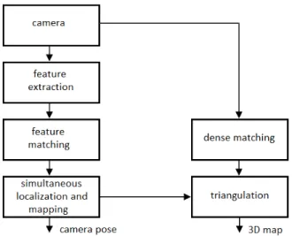
In Fig. 1 an overview of our algorithm is shown. The algorithm is based on how to increase the 3D map density and at the same time allow real-time processing. Considering that increasing the map density is an exhaustive task that implies high computational demand, we formulate our algorithms in such a way it facilitates hardware acceleration.
A. Feature extraction
Several types of local features can be extracted (edges, blobs, corners, etc.) and several types of feature extraction algorithms can be used. In the case of monocular-SLAM, there is a tendency of using corners as the unique local feature considered in the SLAM formulation [9]. A corner can be defined as a point, whose immediate neighborhood contains two or more dominant edges of different directions. Several detectors, for example SUSAN [12], Harris [10] or Shi-Tomasi [13] have been used in SLAM formulations, however, they are computationally intensive and the processing time is high. In recent years, the Features from Accelerated Segment Test (FAST) [11], has become the most used corner detection algorithm because it enables low processing time and low computational demand and it is what we will use in this work. The original FAST-N algorithm compares the intensity of a corner candidate c with each point from a 16-point circle that surrounds c, as shown in Fig. 2. Then, a feature is detected at c if the grayscale intensities of at least G contiguous pixels are all above or all below the intensity of c by some threshold, t. For more details see [11].
Fig. 2: Relations of the center pixel c and its surrounding pixels in the FAST algorithm. Image taken from [11]
B. Feature tracking
In the case of monocular-SLAM formulations, two types of feature-tracking algorithms can be used: feature-tracking algorithms based on two viewpoints and feature tracking algorithms based on frame-by-frame tracking. For algorithms based on two viewpoints, they allow feature matching along large trajectories with a relatively low processing time [20, 21]. However, the image degradation between viewpoints intro-duces data inconsistencies that introduce erroneous matches. On the other hand, algorithms based on frame by frame track-ing deliver high accuracy without data inconsistencies, but processing time is high and hardware acceleration is complex [22, 23]. In this work, we are interested to increase the 3D map density in monocular-SLAM systems based on RGB cameras. Dense mapping requires large number of feature points that are being tracked. Considering that, all feature tracking algorithms in the literature present important limitations since they have wrong matches for algorithms based on two viewpoints and low speed processing for algorithms based on frame-by-frame tracking, in this work, we propose a new feature- tracking
algorithm that searches for a region centered in any feature g in frame i that is similar or equal than a similar size region in frame i + 1, located within a search region in frame i + 1. Similar to KL [22] algorithm, we propose search regions. But, instead of rectangular patches, we propose circular patches that minimize the inconsistent pixels introduced by rotational motion, this is illustrated in Fig. 2.
Fig. 3:Circular patches vs. rectangular patches. When a rectangular patch in an image A (top-left) is compared with a same size rectangular patch in an image B (top-right), rotation motion introduce inconsistent values (these are represented as white pixels within the rectangular patch). If a circular patches instead of rectangular is used (bottom-left), any inconsistent data are avoided. This can be observed in bottom-right in which pixels within the circle are the same those pixels within circle shown in the bottom-left of the image.
We define the radius size (r) as shown in Eq. 1, where r is an integer number that represent the radius size and σ is computed as shown in Eq. 2, where X is the horizontal resolution for the input images measured in pixels while Y is the vertical resolution.
r = min{k ∈ Z | ρ ≤ k} (1) σ = X + Y
4 ·√X + Y (2) Then, we construct a rectangular patch defined as G = 02·r+1,2·r+1. In this case, rectangular patches provide
straight-forward implementation in FPGA, since rectangular patches can be mapped into RAM buffers with relatively low memory management complexity. After the rectangular patch is com-puted, we construct a circular region within the patch, this is computed as shown in Eq. 3, where G is a rectangular patch and ik,θ, jk,θ are computed as shown in Eq. 4, 5
respectively. r is the radius computed by Eq. 1 and α is a barrier value defined by the user. Note that Eq. 4, 5 is a modified vectored circumference equation that constructs circular perimeters defined by integer values. Combining Eq. 4 and 5 with Eq. 3 a circular with region radius r can be constructed. G = 1 ∀ Gak,θ,bk,θ (3) ik,θ= r X k=0 α X θ=0 min{ϑ ∈ Z|(k + cos(2π · θ/α)) ≤ ϑ} (4)
jk,θ = r X k=0 α X θ=0 min{ϑ ∈ Z|(k + sin(2π · θ/α)) ≤ ϑ} (5) Finally, we can assume that a feature point q in frame i have a displacement in frame i + 1 less or equal than r. Therefore, we can construct one circular patch over a feature point q with coordinates (x,y) in frame i. Then, we can construct n circular patches in frame i + 1, in this case, the n region centers are all points within the search region (circle with radius r centered in coordinates (x, y)) in frame i, see Fig. 4. Finally, by applying any type of correlation function, we can assume that n region center that minimizes or maximizes the correlation function is the tracked position of the feature point q in frame i + 1.
Fig. 4:The proposed feature-tracking algorithm formulation. For each feature point, n overlapped patches are constructed in frame i + 1, n patches centers are all points within the circular patch created in frame i. n region center that minimizes or maximizes a correlation function is the tracked position of the feature point q in frame i + 1.
The sum of squared differences (SAD) has low mathemat-ical complexity and enables simple FPGA or GPU imple-mentation. Therefore, we propose a SAD correlation function adapted to our circular patches. In this scenario, we propose Eq. 6 and 7; where xi+1(h), yi+1(h) are the spatial locations
for all the g features in frame i + 1. SAD measures the similarity between patches by applying the sum of squared differences, as shown in Eq. 8, where r is the search region size, computed via Eq. 1, considering X, Y as the horizontal, vertical resolution of the input images. Ii and Ii+1 represent
the 2D spatial coordinates of pixels for two different frames from an image sequence, and β, σ are the spatial location for all the patches in frame i + 1, they ranges between r up to r with increments of 1. xi+1(h) = g X h=1 minβSAD(β, σ) (6) yi+1(h) = g X h=1 minσSAD(β, σ) (7) SAD(β, σ) = u=r X u=−r v=r X v=−r G(u + r + 1, v + r + 1) · (8) |(Ii(x + u, y + v) − Ii+1(x + u, y + v))|
C. Simultaneous localization and mapping
Given two corresponding point sets: q = {(x1, y1), (x2, y2)
· · · (xn, yn)}, g = {(x1, y1), (x2, y2) · · · (xn, yn)}, the
fun-damental matrix F can be computed by applying camera geometry analysis. Then, the essential matrix E can be es-timated as E = K0F K, where K is the calibration matrix for the camara used in the SLAM formulation. By applied singular value decomposition (SV D) over E and solving for a close solution, the camera matrix P can be estimated. For more details about camera matrix estimation see [24]. Using the P matrix and the corresponding point sets, the Least Squares algorithm [25] estimates the translation t and rotation R that minimizes the sum of the squared re-projection error. Then, using again q, g and considering the P matrix, any linear triangulation method can estimate the 3D position of all tracked points. Finally, any optimization technique such as, bundle adjustment or LevenbergMarquardt modifications can be used to simultaneously refine the camera pose (t, R) and the 3D positions. In this work, we use bundle adjustment as optimization technique since this has proved successful in the past and is the most common optimization technique used in current monocular-SLAM systems.
D. Dense tracking
In order to reach dense tracking, we propose a modification of our feature tracking algorithm (Section III-B). In general, considering A as a input image sequence, we consider g as all points from an image within the sequence, defined as xi(g) = x, yi(g) = y; where x, y are the 2D spatial position
for all points/pixels in the image. Then, we can track all points similar to the Section III-B formulation. But, in this case, we propose eliminating any point correspondence if there are two or more different indexes (β, σ) that minimize the correlation function (Eq. 8). This is because we assumed that if there are two or more different indexes that minimize the correlation function, the tracked point is within an untextured region. i.e., any point/pixel within the search region in the frame i + 1 minimizes the cost function, thus, estimate the position in frame i+1 is impossible if only color comparisons are applied in the correlation function.
E. Triangulation
Given two corresponding point sets: q = {(x1, y1), (x2, y2) · · · (xn, yn)},, g =
{(x1, y1), (x2, y2) · · · (xn, yn)}, and considering
(P1, P2) as the camera matrix estimated via the
Essential matrix and camera matrix centered at the origin, respectively, we can compute the following variables: A1 = q(x1) · P1(3, i) − P1(1, i), A2 =
q(y1)·P1(3, i)−P1(1, i), A3= q(x1)·P2(3, i)−P2(1, i), A3=
q(y1)·P2(3, i)−P2(1, i), A[A1A2A3A4]. Finally, let [U S V ]
denote the singular value decomposition (SV D) over A, the 3D positions for all the tracked points (the mapping solution of the SLAM process) can be denoted as V (i, 4). For more details about linear triangulation see [24].
IV. RESULTS AND DISCUSSION
In this section preliminary results for our SLAM formu-lation are presented. For that, first we present experimental results for our feature-tracking algorithm. We compare the performance for several feature-tracking algorithms previously used in SLAM formulations. Second, we show experimental results for our dense-tracking algorithm.
A. The feature tracking algorithm
In Fig. 5, feature tracking performance by applying our algorithm is shown. In these tests, we tracked features obtained via the FAST algorithm [11] with the following frame of a video sequence.
Fig. 5: Feature-tracking algorithm applied over two consecutive frames form an outdoor video sequence
In order to measure the performance of our feature tracking algorithm, we implemented several feature-tracking algorithms suitable for SLAM formulations via Matlab scripts. Then, we track feature points extracted via the FAST algorithm across 16 consecutive frames from eight different video sequences, respectively. In TABLE I, accuracy comparisons are shown, we present the mean accuracy for all the compared algorithms. In the case of the SURF/ORB [20, 21] algorithms, they allow feature matching along large trajectories with a relatively low processing time, but, the image degradation between viewpoints introduces data inconsistences that introduce er-roneous matches. In order to achieve accuracy required by SLAM applications, statistically robust methods like Random Sample Consensus (RANSAC) have to be implemented to filter erroneous matches. Our algorithm allows high accuracy, superior to SURF/ORB, suitable for SLAM applications and without any filter or post-processing step. The only limitation of our algorithm compared with SURF/ORB is that a frame by frame feature-tracking approach is an exhaustive task. Then, the processing time have to be higher than two viewpoint approaches. This can be observed in TABLE II, were our algorithm and the KLT algorithm [22], both frame by frame feature tracking algorithms, have higher processing time than SURF/ORB. Nevertheless, our algorithm has an important advantage because its mathematical formulation allows sim-ple FPGA imsim-plementation, suitable for real-time processing. Considering that previous work do not allow simple hardware implementation or do not provide accuracy suitable for SLAM applications, our feature matching approach can provide a convenient framework for SLAM formulations since it enables high accuracy and allows simple FPGA implementation for real-time processing.
TABLE I: Accuracy of feature-tracking algorithms used in SLAM formulations (errors are measured in pixels, all sequences were obtained from [26]).
Dataset SURF ORB KLT proposed fr1/room 79.38 76.24 0.21 1.97 fr2/desk 81.12 73.63 0.45 1.76 fr1/plant 77.74 75.24 0.39 1.83 fr1/teddy 83.53 76.73 0.47 1.94 fr2/coke 80.78 75.28 0.32 1.73 fr2/dishes 78.25 74.19 0.01 1.67 fr3/cabinet 79.87 74.02 0.42 1.71 fr3/teddy 79.10 75.21 0.46 1.83 mean errors = 79.97 75.08 0.34 1.63
TABLE II: Processing speed of feature-tracking algorithms used in SLAM formulations (times are measured in secons, all sequences were obtained from [26]).
Dataset SURF ORB KLT proposed fr1/room 1.92 0.41 16.34 8.1 fr2/desk 2.11 0.47 16.74 8.9 fr1/plant 2.13 0.43 16.24 8.3 fr1/teddy 1.97 0.37 16.74 4.7 fr2/coke 2.04 0.53 16.41 8.8 fr2/dishes 1.82 0.33 16.75 4.7 fr3/cabinet 2.15 0.35 16.13 4.6 fr3/teddy 2.19 0.59 16.29 12.1 mean time = 2.04 0.43 16.41 7.52 B. Dense tracking
In Fig. 5, dense tracking performance by applying our algorithm is shown. In this case, the lines (correspondences between points) overlap in most the image. This is because instead of feature tracking in which only corners are tracked, in dense tracking, all points in the images have to be tracked, therefore, there have to be one line that connected any point in the first image with its corresponding point in the second image.
Fig. 6: Dense-tracking algorithm applied over two consecutive frames form an outdoor video sequence
C. monocular-SLAM
In order to validate the performance, we tested via Mat-lab several indoor/outdoor video sequences. Although there are several datasets, in most cases several environmental restrictions such as, controlled illumination, uniform camera movements and less image degradation between frames are considered. Environmental restrictions limit the real-world applications performance since these restrictions often are not present. In this work, all video sequences were captured in the interior/exterior of our campus. Then, it is demonstrated that the proposed solution is capable to work in satisfactory form under several real-world conditions.
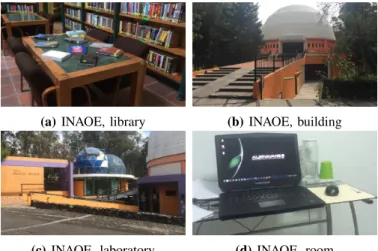
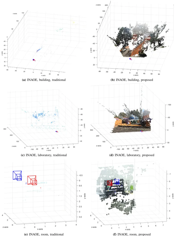
In Fig. 7 an overview of some tested scenes are shown while in Fig. 8 and 9, we present the results for our monocular-SLAM algorithm compared with a traditional monocular-SLAM approach. For that, we formulate a tradi-tional monocular-SLAM approach using the FAST algorithm [11] in the feature extraction step, the BRIEF visual descrip-tor [27] in the visual descripdescrip-tor step, a traditional all vs. all matching algorithm, the normalized eight-point algorithm for the camera pose estimation [25], the linear triangulation algorithm for the 3D estimation and bundle adjustment to simultaneously refine camera pose and 3D points. As can be seen, in all cases the point cloud density can be increased by applying our monocular-SLAM algorithm. Furthermore, we demonstrated that the proposed algorithm works successfully under different environmental conditions, different places and different camera movements. Therefore, the proposed solution addressed in satisfactory form the sparse cloud problem.
(a) INAOE, library (b) INAOE, building
(c) INAOE, laboratory (d) INAOE, room Fig. 7: General view of several real-world scenes tested in our monocular-SLAM algorithm.
In TABLE III we present numerical comparisons between the traditional and proposed monocular-SLAM approach. In all cases high accuracy in the camera pose estimation can be achieved. In all cases, the proposed dense tracking algorithm allows increasing the point cloud density. Considering that previous work that addressed the sparse cloud problem using a single RGB camera, such as DT-SLAM [19], LSD-SLAM [15] and ORB-SLAM [14], only include near to 2, 7 and 4 percent of the points from a scene, respectively. Then, our algorithm that can include a mean of 14 percent of the points form a scene, improves the current state of the art, providing dense mapping and accurate camera pose estimation under several real-world indoor/outdoor scenarios. Finally, all exhaustive algorithms such as, feature extraction, feature tracking and dense tracking allow straightforward implementation in FPGA. In the case of the feature/dense tracking algorithms, all pixels/patches can be compared in parallel. This could allow real-time processing that increases the scope of our monocular-SLAM algorithm.
TABLE III: Numerical comparisons between the traditional and proposed monocular-SLAM approach
Sequence camera
pose error 3D map density
camera
pose error 3D map density library 0.0087% 161 points 0.0087% 280014 points building 0.0123% 217 points 0.0123% 330291 points laboratory 0.0127% 289 points 0.0127% 376284 points room 0.0083% 119 points 0.0083% 193247 points traditional proposed
V. CONCLUSIONS
In this article, we introduced a new feature-tracking/dense-tracking algorithm, suitable for increasing the density of the monocular-SLAM systems based in RGB cameras, and that allow simple hardware implementation for real-time process-ing. Our SLAM formulation delivers accurate camera pose and dense mapping, superior to previous work. We have demonstrated that our SLAM formulation can be successfully applied under several real-world scenarios. Finally, based on the mathematical formulation of all our algorithms, we can affirm that a simple and compact FPGA implementation can be implemented; this will enable real-time processing with low cost and compact system design.
(a) INAOE, library, traditional
(b) INAOE, library, proposed
Fig. 8: 3D mapping performance for the proposed monocular-SLAM formulation compared with the traditional formulation.
(a) INAOE, building, traditional (b) INAOE, building, proposed
(c) INAOE, laboratory, traditional (d) INAOE, laboratory, proposed
(e) INAOE, room, traditional (f) INAOE, room, proposed
REFERENCES
[1] S. Thrun, D. Hahnel, D. Ferguson, M. Montemerlo, R. Triebel, W. Burgard, C. Baker, Z. Omohundro, S. Thayer, and W. Whittaker, “A system for volumetric robotic mapping of abandoned mines,” in Robotics and Automation, 2003. Proceedings. ICRA’03. IEEE Interna-tional Conference on, vol. 3. IEEE, 2003, pp. 4270– 4275.
[2] C. F. Olson, L. H. Matthies, J. R. Wright, R. Li, and K. Di, “Visual terrain mapping for mars exploration,” Computer Vision and Image Understanding, vol. 105, no. 1, pp. 73–85, 2007.
[3] D. Chekhlov, A. P. Gee, A. Calway, and W. Mayol-Cuevas, “Ninja on a plane: Automatic discovery of physical planes for augmented reality using visual slam,” in Proceedings of the 2007 6th IEEE and ACM Inter-national Symposium on Mixed and Augmented Reality. IEEE Computer Society, 2007, pp. 1–4.
[4] J. M. Carranza, “Efficient monocular slam by using a structure-driven mapping,” Ph.D. dissertation, Citeseer, 2012.
[5] W. Tan, H. Liu, Z. Dong, G. Zhang, and H. Bao, “Robust monocular slam in dynamic environments,” in Mixed and Augmented Reality (ISMAR), 2013 IEEE International Symposium on. IEEE, 2013, pp. 209–218.
[6] S. A. Holmes and D. W. Murray, “Monocular slam with conditionally independent split mapping,” Pattern Analysis and Machine Intelligence, IEEE Transactions on, vol. 35, no. 6, pp. 1451–1463, 2013.
[7] A. Concha and J. Civera, “Using superpixels in monoc-ular slam,” in Robotics and Automation (ICRA), 2014 IEEE International Conference on. IEEE, 2014, pp. 365–372.
[8] A. J. Davison, I. D. Reid, N. D. Molton, and O. Stasse, “Monoslam: Real-time single camera slam,” Pattern Analysis and Machine Intelligence, IEEE Transactions on, vol. 29, no. 6, pp. 1052–1067, 2007.
[9] J. Fuentes-Pacheco, J. Ruiz-Ascencio, and J. M. Rend´on-Mancha, “Visual simultaneous localization and mapping: a survey,” Artificial Intelligence Review, vol. 43, no. 1, pp. 55–81, 2015.
[10] C. Harris and M. Stephens, “A combined corner and edge detector.” in Alvey vision conference, vol. 15. Citeseer, 1988, p. 50.
[11] E. Rosten and T. Drummond, “Fusing points and lines for high performance tracking,” in Computer Vision, 2005. ICCV 2005. Tenth IEEE International Conference on, vol. 2. IEEE, 2005, pp. 1508–1515.
[12] S. M. Smith and J. M. Brady, “Susana new approach to low level image processing,” International journal of computer vision, vol. 23, no. 1, pp. 45–78, 1997. [13] J. Shi and C. Tomasi, “Good features to track,” in
Com-puter Vision and Pattern Recognition, 1994. Proceedings CVPR’94., 1994 IEEE Computer Society Conference on. IEEE, 1994, pp. 593–600.
[14] R. Mur-Artal, J. Montiel, and J. D. Tardos, “Orb-slam: a versatile and accurate monocular slam system,” Robotics, IEEE Transactions on, vol. 31, no. 5, pp. 1147–1163, 2015.
[15] J. Engel, T. Sch¨ops, and D. Cremers, “Lsd-slam: Large-scale direct monocular slam,” in Computer Vision–ECCV 2014. Springer, 2014, pp. 834–849.
[16] S. Thrun, M. Montemerlo, H. Dahlkamp, D. Stavens, A. Aron, J. Diebel, P. Fong, J. Gale, M. Halpenny, G. Hoffmann et al., “Stanley: The robot that won the darpa grand challenge,” Journal of field Robotics, vol. 23, no. 9, pp. 661–692, 2006.
[17] B. He, L. Ying, S. Zhang, X. Feng, T. Yan, R. Nian, and Y. Shen, “Autonomous navigation based on unscented-fastslam using particle swarm optimization for au-tonomous underwater vehicles,” Measurement, vol. 71, pp. 89–101, 2015.
[18] M. Johnson-Roberson, O. Pizarro, S. B. Williams, and I. Mahon, “Generation and visualization of large-scale three-dimensional reconstructions from underwater robotic surveys,” Journal of Field Robotics, vol. 27, no. 1, pp. 21–51, 2010.
[19] C. Herrera, K. Kim, J. Kannala, K. Pulli, J. Heikkila et al., “Dt-slam: Deferred triangulation for robust slam,” in 3D Vision (3DV), 2014 2nd International Conference on, vol. 1. IEEE, 2014, pp. 609–616.
[20] E. Rublee, V. Rabaud, K. Konolige, and G. Bradski, “Orb: an efficient alternative to sift or surf,” in Computer Vision (ICCV), 2011 IEEE International Conference on. IEEE, 2011, pp. 2564–2571.
[21] H. Bay, T. Tuytelaars, and L. Van Gool, “Surf: Speeded up robust features,” in Computer vision–ECCV 2006. Springer, 2006, pp. 404–417.
[22] B. D. Lucas, T. Kanade et al., “An iterative image reg-istration technique with an application to stereo vision.” in IJCAI, vol. 81, 1981, pp. 674–679.
[23] C. Tomasi and T. Kanade, Detection and tracking of point features. School of Computer Science, Carnegie Mellon Univ. Pittsburgh, 1991.
[24] R. Hartley and A. Zisserman, Multiple view geometry in computer vision. Cambridge university press, 2003. [25] W. Conley, “Computer optimization techniques,” Tech.
Rep., 1980.
[26] C. V. Group. (2016) Rgb-d slam dataset and benchmark. [Online]. Available: https://vision.in.tum.de/data/datasets/rgbd-dataset/download
[27] M. Calonder, V. Lepetit, C. Strecha, and P. Fua, “Brief: Binary robust independent elementary features,” Com-puter Vision–ECCV 2010, pp. 778–792, 2010.