Design and Construction of the
Versatile Toroidal Facility for
Ionospheric Chamber Research
by
Robert F Duraski
S.B.,Nuclear Engineering,University of Illinois Urbana-Champaign,
(1988)
Submitted to the Department of Nuclear Engineering
in partial fulfillment of the requirements for the degree of
Master of Science in Nuclear Engineering
at the
MASSACHUSETTS INSTITUTE OF TECHNOLOGY
AUGUST 1991
@Massachusetts
Institute of Technology 1991. All rights reserved.
Signature redacted
A uth or...
Department of Nuclear Engineering
August1y, 1991
Signature redacted
C ertified by
... ..
----Prof. Min-Chang Lee
Thesis Supervisor
Certified by
...
Signature redacted
Prof.
Jeffrey P. Freidberg
Thesis Reader
Signature redacted
A ccepted by...
Prof. Allen F. i4enry
ChairmanDepartmental Committee on Graduate Students
MASSAUAUS-TjS INSTITUTE
OF TECHNOW OGY
J
A N
2 11992
77 Massachusetts Avenue
Cambridge, MA 02139
MgTLibranes
http://Iibraries.mit.edu/askDISCLAIMER NOTICE
Due to the condition of the original material, there are unavoidable flaws in this reproduction. We have made every effort possible to
provide you with the best copy available. Thank you.
Some pages in the original document contain text that is illegible.
Design and Construction of the
Versatile Toroidal Facility for
Ionospheric Chamber Research
by
Robert F. Duraski
Submitted to the Department of Nuclear Engineering on August 13, 1991, in partial fulfillment of the
requirements for the degree
Master of Science in Nuclear Engineering
ABSTRACT
This thesis describes the design and construction of the Versatile Toroidal Facility (VTF) located in the Plasma Fusion Center's Nabisco Laboratory. The VTF has a major radius of 0.9 m, a minor radius of 30 cm and a maximum toroidal field of 1 Tesla. The two functions of the VTF are the simulation of ionospheric plasma and thermonuclear fusion research. At present the machine is capable of ionospheric applications and work towards fusion study capabilities are still in progress.
Thesis Supervisor: Prof. Min-Chang Lee
Title: Leader, Plasma Fusion Center Ionospheric Plasma Research Group
ACKNOWLEDGMENTS
The author extends his thanks to the Air Force Office of Scientific Research for funding such a long shot. Many talents have been enhanced by this gift.
A special thanks to my advisor, Dr M.C.Lee, for both his moral support and the
opportunity to work on a project of such magnitude.
I am also indebted to Dr. M. Gaudreau, Dr. R. Parker and Dr. S. Luckhardt
for their guidance during the construction of this facility and for allowing us the freedom to accomplish it.
I am grateful to F. Silva, B. Cochran, M. Olmstead, B. Keating, B. Childs and the rest of the Alcator C-Mod Staff for their advice and cooperation during this enterprise. Without this help the machine would not be standing.
My appreciation also goes out to my family and friends who supported me during
this pleasant madness.
A special thanks to P. Dandridge and the Employees at Atomic Limited for their
personal concern with our goals and the enjoyable discussions.
My warmest regards go out to the VTF crew. The friendship, cooperation
and mutual respect forged during this journey will always be a personal source of pleasure and pride. In particular, I wish to mention D. Stracher, D. Beals, C. Shutts, F. Leibly, R. West, J. Garnish, C. Yoo, K. Vilece and D. Moriarty for their unique contributions.
And finally, to those who will sail on her in the future, enjoy. I'll be watching for your correspondence.
Contents
1 INTRODUCTION 11
1.1 HISTORY OF THE VTF ... 11
1.2 CONSTRUCTION OF THE VTF ... 14
1.3 THE PHILOSOPHY OF THIS THESIS ... 18
2 THE VTF SUPPORT STRUCTURES 19 2.1 THE CONCRETE BLOCK ... 19
2.1.1 DESIGN AND CONSTRUCTION OF THE BLOCK ... .20
2.1.2 TEST AND LIMITS OF THE CONCRETE BLOCK . . . 23
2.1.3 PROBLEMS WITH THE CONCRETE BLOCK ... 24
2.2 THE INNER SUPPORT RING ... 24
2.2.1 DESIGN AND CONSTRUCTION OF THE INNER SUP-PORT RING ... 24
2.2.2 TEST AND LIMITS OF THE INNER SUPPORT RING . . . 26
2.2.3 PROBLEMS WITH THE INNER SUPPORT RING ... 26
2.3 THE SUPPORT STAND ... 28
2.3.1 DESIGN AND CONSTRUCTION OF THE SUPPORT STAND 28 2.3.2 TEST AND LIMITS OF THE SUPPORT STAND ... 33
2.3.3 PROBLEMS WITH THE SUPPORT STAND ... 33
3 THE TOROIDAL FIELD SYSTEM 34 3.1 THE BUCKING CYLINDER ... 34
3.1.1 DESIGN AND INSTALLATION OF THE BUCKING CYLIN-D E R . . . .
3.1.2 TEST AND LIMITS OF THE BUCKING CYLINDER ....
3.1.3 PROBLEMS WITH THE BUCKING CYLINDER ...
3.2 THE TOROIDAL FIELD COILS ...
3.2.1 DESIGN AND INSTALLATION OF THE TOROIDAL FIELD
3.2.2 3.2.3 3.3 THE 3.3.1 3.3.2 3.3.3 SY STEM . . . .. . .. . . .. . . . .
TEST AND LIMITS OF THE TOROIDAL FIELD COILS.
PROBLEMS WITH THE TOROIDAL FIELD COILS .
TOROIDAL FIELD BUS ...
DESIGN AND CONSTRUCTION OF THE TOROIDAL FIELD
B U S. . . . TEST AND LIMITS OF THE TOROIDAL FIELD BUS ...
PROBLEMS WITH THE TOROIDAL FIELD BUS ... 4 THE INNER AND OUTER TORQUE CYLINDERS
4.1 THE INNER TORQUE CYLINDER ...
4.1.1 DESIGN AND INSTALLATION OF THE INNER TORQUE
CYLINDER ...
4.1.2 TEST AND LIMITS OF THE INNER TORQUE CYLINDER
4.1.3 PROBLEMS WITH THE INNER TORQUE CYLINDER . .
4.2 THE OUTER TORQUE CYLINDER ...
4.2.1 DESIGN AND INSTALLATION OF THE OUTER TORQUE
CYLINDER ...
4.2.2 TEST AND LIMITS OF THE OUTER TORQUE CYLINDER
34 35 36 36 36 39 42 43 43 45 45 46 46 46 47 47 48 48 52
4.2.3 PROBLEMS WITH THE OUTER TORQUE CYLINDER.. 52
5 THE VACUUM SYSTEM 53
5.1.1 DESIGN AND CONSTRUCTION OF THE VACUUM
CHAM-BER...
5.1.2 TEST AND LIMITS OF THE VACUUM CHAMBER ....
5.1.3 PROBLEMS WITH THE VACUUM CHAMBER ...
5.2 THE MATING FLANGES ...
5.2.1 DESIGN AND CONSTRUCTION OF THE FLANGES ....
5.2.2 TEST AND LIMITS OF THE MATING FLANGES ...
5.2.3 PROBLEMS WITH THE MATING FLANGES ...
5.3 SURFACE PREPARATION ...
5.4 THE VACUUM PUMPING SYSTEM ...
5.4.1 DESIGN AND CONSTRUCTION OF THE VACUUM
PUMP-ING SYSTEM ...
5.4.2 TEST AND LIMITS OF THE VACUUM PUMPING SYSTEM
5.4.3 PROBLEMS WITH THE VACUUM PUMPING SYSTEM . .
6 THE OHMIC COIL SYSTEM
6.1 THE OHMIC COILS ...
6.1.1 DESIGN AND CONSTRUCTION OF THE OHMIC COILS
6.1.2 TEST AND LIMITS OF THE OHMIC COILS ...
6.1.3 PROBLEMS WITH THE OHMIC COILS ...
6.2 THE NULL FIELD COILS ...
6.2.1 DESIGN AND CONSTRUCTION OF THE NULL COILS .
6.2.2 TEST AND LIMITS OF THE NULL COILS ...
6.2.3 PROBLEMS WITH THE NULL COILS ...
6.3 THE TRIM COILS ...
6.3.1 DESIGN AND CONSTRUCTION OF THE TRIM COILS .
6.3.2 TEST AND LIMITS OF THE TRIM COILS ...
6.3.3 PROBLEMS WITH THE TRIM COILS ...
6.4 OHMIC SYSTEM PERFORMANCE ...
53 61 63 63 63 66 66 67 68 68 71 71 73 73 76 79 80 81 81 84 84 85 86 88 88 89
7 THE EQUILIBRIUM SYSTEM AND PARAIL COILS
7.1 THE EQUILIBRIUM FIELD COILS ... 95
7.1.1 THE FOUR-TURN EF COILS ... 97
7.1.2 THE TWO-TURN EF COILS ... 97
7.1.3 THE ANTI-TRANSFORMER COIL ... . . . 99
7.1.4 TEST AND LIMITS OF THE EF COILS ... 7.1.5 PROBLEMS WITH THE EF COILS ... 7.1.6 PERFORMACE OF THE EF COILS ... . . . 99
. . . 99
7.2 THE PARAIL COILS ... .101
7.2.1 DESIGN AND CONSTRUCTION OF THE PARAIL COILS 101 7.2.2 TEST AND LIMITS OF THE PARAIL COILS ... . . . . .101
7.2.3 PROBLEMS WITH THE PRAIL COILS ... 101
7.2.4 PERFORMANCE OF THE PRAIL COILS ... 103
8 CONCLUSION 106 107 A ERRORS IN PREVIOUS CALCULATIONS A.1 MODIFICATIONS TO THE BUCKLING OF THE SUPPORT RING'S CONCRETE FILLED COLUMNS ... 107
A.2 CORRECTIONS TO THE OHMIC COIL SAFETY FACTOR CAL-CULATION ... 108
B FREQUENTLY USED FORMULAS 120 B.1 CALCULATION OF THE TEMPERATURE INCREASE IN A CUR-RENT CARRYING CABLE ... 120
B.2 CALCULATION OF THERMAL EXPANSION FORCES IN A COM-POSITE STRUCTURE ... 122 C PAPERS GENERATED 124 127 D PERSONNEL . 99 95
List of Tables
1.1 VTF LOW POWER PARAMETERS ...
1.2 VTF HIGH POWER PARAMETERS ...
3.1 TOROIDAL FIELD COIL FINAL POSITIONING RESULTS ...
3.2 TF COIL INDUCTANCE AND RESISTANCE TEST RESULTS .
6.1 OH SYSTEM OPERATING PARAMETERS ...
A.1 USEFUL MATERIAL PROPERTIES ...
. 12 . 13 . 38 . 40 . 94 . 119
List of Figures
1.1 CROSS-SECTION OF THE VTF ...
CONCRETE BLOCK ... 21
CONCRETE BLOCK REINFORCING BAR DIAGRAM ... .22
INNER SUPPORT RING ... 25
CONCRETE PAD BRACING ... 27
THE SUPPORT STAND ... 29
SUPPORT STAND OUTER JOINT ... 30
SUPPORT STAND BRACING TO WEST WALL ... 32
TOROIDAL FIELD COIL ... 37
TOROIDAL FIELD COIL JOINTS ... 41
TOROIDAL FIELD BUS CROSS-SECTION ... 44
4.1 TOP VIEW OF BRACE ... VACUUM CHAMBER AND TF COILS . . . TOP/BOTTOM PORT FLANGE ... LOCATION OF PARALLEL VIEW PORTS. PARALLEL VIEW ENTRY PORT ... PARALLEL VIEW EXIT PORT ... . . . 50 . . . 54 . . . 56 . . . 58 . . . 59 ... ... 60 VACUUM CHAMBER AND OUTER TORQUE CYLINDER LEG
MATING FLANGE ...
MATING FLANGE CROSS SECTION ...
62 64 65 16 2.1 2.2 2.3 2.4 2.5 2.6 2.7 3.1 3.2 3.3 5.1 5.2 5.3 5.4 5.5 5.6 5.7 5.8
5.9 THE VACUUM PUMPING SYSTEM ... 5.10 VTF PUMP DOWN CURVE ...
6.1 VTF OH COIL POSITIONS ...
6.2 UNWRAPPED PARTIAL VIEW OF INNER TC COILS . 6.3 VTF OH COIL BUS BARS ...
6.4 NULL COIL BRACKET ...
6.5 TRIM AND EF COIL BRACKET ...
6.6 OH SOLENOID FIELD AT Z =0 ...
6.7 MAGNETIC FLUX OF OH SYSTEM ...
6.8 NULL COIL FIELD AT Z =0 ...
6.9 TRIM COIL FIELD AT Z =0 ...
7.1 VTF EF COIL POSITIONS ...
7.2 2-TURN EF COIL AND PARAIL COIL SUPPORTS ...
7.3 FIELD PRODUCED BY THE EF COILS AT Z = 0 ....
7.4 FIELD INDEX OF THE EF COILS ...
7.5 VERTICAL FIELD FROM THE PARAIL COILS ...
7.6 CONFINMENT TIME VS VERTICAL FIELD STRENGTH
A.1 GEOMETRY OF OH COIL CALCULATIONS ...
. . ....74 75 78 82 87 90 91 92 93 96 98 . . . . . 100 . . . 102 . . . 104 . . . 105 . 110 69 72
Chapter 1
INTRODUCTION
As the name implies, the Versatile Toroidal Facility (VTF) is designed to study plasma under a variety of parameters and for a variety of applications. The initial regime of study is for ionospheric applications and the parameters for these "low power" experiments are presented in Table 1.1. Long term "high power" parameters, which include fusion studies, are given in Table 1.2. The rest of this chapter will discuss the history of the VTF, give an outline of the construction of the machine and describe the philosophy of this thesis.
1.1
HISTORY OF THE VTF
Originally, the VTF was called the Versator II Upgrade which was proposed by Drs. R.Post and M.Porkolab in 1987. With funding promised from the Department of Energy (DOE), the major components of the Versator Upgrade were acquired from the University of Wisconsin, which originally obtained these parts from the Impurity Studies Experiment (ISX) at Oak Ridge National Laboratory. The toroidal field coils and bucking cylinder were assembled for the ISX-A machine and later used in the ISX-B experiment, while the inner and outer torque cylinders were fabricated
for ISX-B.
THE VERSATILE TOROIDAL FACILITY LOW POWER PARAMETERS
(TABLE 1.1)
Major Radius Minor Radius Pulse Length RF Power
Microwave ECR Frequency Electron Temperature Ion Temperature
Toroidal Magnetic Field Vertical Magnetic Field Density
Parail Confinement Time
Elec/Ion Thermal Equilibrium Time Recombination Time
Electron collision Frequency
0.9m 0.3m 1hr 3.0kW 2.45GHz 10ev lev 89OGauss 4.5Gauss 10 7#/m 3 lms 0.23ms 8.5X10 4#/m 3 1.3X10⁵#/sec 12
THE VERSATILE TOROIDAL FACILITY HIGH POWER PARAMETERS
(TABLE 1.2) Major Radius Minor Radius Pulse Length RF Power Ellipticity Electron Temp Ion Temp
Toroidal Magnetic Field Aspect Ratio
Density
Kaye-Goldston Confinement Time
0.9m 0.3m 0.15sec 2.0MW 1.4 0.7kev 0.3kev 1.OTesla 3.0 2X10¹⁹#/m3 lms 13
limitations at the DOE resulted in the cancellation of the funding for the Versator project. It was at this point that Dr R.R. Parker and Dr M. Gaudreau decided to continue the construction of the machine, since all the high cost items (with the exception of the vacuum chamber) were available from the ISX project and the Tara Mirror machine at MIT. So in December of 1988, with very little capital, construction of the Versator upgrade was began in the Tara cell of MIT's Nabisco Laboratory (NW12-122). It was also proposed, in order to reduce costs, to build the machine using undergraduate students from the Institute via the Undergraduate Research Opportunity Program (UROP).
Later, in the Summer of 1989, Dr M.C. Lee's Ionospheric Plasma Research Group became interested in the project and obtained funding from the Air Force Office Of Scientific Research (AOSOR) under a program monitored by Dr. R.J. Barker. While this new funding source was of substantial help, it was still not possible to hire a professional staff and so it was decided to continue building the machine with Dr. Lee's graduate students together with undergraduate students supported partially
by the UROP office. It was also at this time the name of the facility was changed
to the Versatile Toroidal Facility to reflect design modifications made in order to perform simulation experiments for ionospheric plasma research.
My involvement in this project as Dr. Lee's graduate student, was to coordinate
this student "labor" force during the assembly of the VTF which generated its first plasma at 6:00 PM on December 31,1990
1.2
CONSTRUCTION OF THE VTF
The nominal crew size on this project was about 17 undergraduates who were ex-pected to put in an average of 15 hours of work per week during the school year and 40 hours per week in the summer. For the undergraduates, the majority of the work during the school year was accomplished on Saturdays with the balance of the required hours being put in at some time during the regular work week. With the exception of welding the vacuum chamber, these students were involved in every
aspect of constructing the machine, but it must be pointed out that the skill level of the average student out of high school alone is not enough to build such a machine. And so substantial assistance in the training of our crew was obtained from the Alcator project at MIT and Atomic Limited in Cambridge, Mass.
As far as a general outline of the assembly of the VTF (a cross-section of one half of the machine is shown in Fig 1.1), the first components to be built were the concrete block and the inner support ring. Next the support stand was installed and the bucking cylinder positioned on the machine. Following this, the toroidal field coils were placed on the stand and the top of the coils removed so the rest of
the components could be installed.
Concurrent with the above work, the coils for the ohmic heating system were wrapped on the inner torque cylinder. The vacuum chamber built. The remaining ohmic and equilibrium field coils fastened to the outer torque cylinder and construc-tion of the toroidal field coil supply and return bus completed.
Once the above work was finished, the lower half of the outer torque cylinder, originally fabricated in two parts so the vacuum chamber could be installed, was fastened to the machine. Next the inner torque cylinder was mounted, followed by the vacuum chamber. Once these were in position, the upper half of the outer torque cylinder was bolted into place, the toroidal field coil tops replaced and the remaining equilibrium field coils wrapped onto the machine. Finally, the vacuum pumping system was installed, the power supplies connected for low power experiments and the diagnostics assembled.
As of this writing the VTF is capable of ionospheric plasma studies and con-struction for fusion research is continuing. To get to this point it took about two years and cost approximately $500,000. The cost were evenly split between labor and materials.
FIGURE 1.1 PARTS LIST
1. TRANSFORMER CORE
2. TRANSFORMER CORE BRACING BEAM
3. VTF CELL DECK
4. CONCRETE BLOCK
5. TOROIDAL FIELD COIL
6. INNER AND OUTER TORQUE CYLINDERS 7. VACUUM CHAMBER
8. RETURN/SUPPLY BUS FOR THE TF COILS 9. INNER SUPPORT RING
10. RADIAL BEAM OF SUPPORT STAND 11. CENTER LINE OF MACHINE
12. BUCKING CYLINDER
13. SUPPORT STAND BRACING TO CONCRETE BLOCK
1.3
THE PHILOSOPHY OF THIS THESIS
Since I have been involved in the management of this project from the beginning until the generation of the first plasma, I am in the position to provide an overview of the design, construction and operation of the VTF. So, for each of the major components this thesis describes:
1) The design and construction of the component
2) Test and limits of the component
3) Problems with the component
While writing this thesis, I have also checked most of the calculations performed for the machine, especially those with which I was involved. Although a complete check was not possible due to time limitations, errors discovered during this verifica-tion are noted in the relevant secverifica-tion by a reference to Appendix A. The calculaverifica-tions not checked include the vacuum pumping system [1] and the ohmic/equilibrium field results [2].
Also included in this thesis are a list of the material properties used in the calculations (App A), common formulas required (App B), papers generated by the project (App C) and a list of all personnel involved in the construction of the VTF
(App D). The references cited in this thesis follow Appendix D.
While this is a comprehensive discussion of the VTF as it now stands, there is still a large amount of work to be done before achieving high power operations. Hence, this thesis can only be considered an initial version of a technical manual for the machine and should be updated once the projects presently underway are complete.
Chapter 2
THE VTF SUPPORT
STRUCTURES
As seen in figure 1.1, the VTF is suspended 127.75" above the concrete floor of the VTF cell and this design was chosen for two reasons. First, it allows access to the bottom ports of the machine. And second, this approach doubles the floor space available since we have two levels, the deck at machine level and the floor of the cell, on which to install equipment.
This chapter will describe the auxiliary components which provide the physical support for the VTF. The machine weighs approximately 32 tons and is designed to incorporate an iron core which is estimated to weigh 40 tons. The components discussed in this chapter are the concrete block, inner support ring and support stand.
2.1
THE CONCRETE BLOCK
The primary purpose of the concrete block is to support the iron core which enhances the magnetic flux coupling between the ohmic coil and plasma. The secondary function of the block is to improve the stability of the VTF in the event of an earthquake.
At present, the iron core design has not been finalized and, due to material cost of $80,000, it probably will not be installed for quite some time. But as proposed, the iron core will be constructed from four 10'X 2'X 2' legs. Each leg will consist of
1600 10'X 2' laminated silicon steel plates 0.015" thick bolted and epoxied together.
The iron core is estimated to weigh 40 tons and will be placed on top of the concrete block as shown in figure 1.1.
2.1.1
DESIGN AND CONSTRUCTION OF THE BLOCK
The block (Fig 2.1) is made from 150 cubic feet of 5000 psi grade concrete reinforced with 1" stainless steel threaded rods (Fig 2.2) and fastened to the VTF cell floor via the vertical reinforcing rods. This fastening was done by drilling 38 holes, 12" to 14" deep, in the cell floor where the main part of the block stands. Twelve more holes, 10" deep, were drilled where the wings of the block are located. Once the holes were made, they were flooded with water and vacuumed out several times until the flushing water contained no visible suspended solids. After the first rod was epoxied into its hole, it was tested as described in Section 2.1.2.
Once the vertical rods were installed, the horizontal rods were attached to them using zip ties and pipe insulation to prevent the formation of a closed conducting loop. Several of the threaded rods were also extended beyond the boundaries of the block so they could be used in the future to secure other components of the machine. Next, a wooden form (oil impregnated for easy removal) was made in preparation to pour the concrete. The geometric layout of the block (Fig 2.1) consisted of an
80" high main body with a 112"X 24" base, the major length of the base running
from North to South. The block does not run the whole length of the machine, but is positioned below the north end. Included with the block are 2 wings, one on both sides of the north end of the main base. These wings were included to improve the vertical stability of the block and allow easy installation of structural supports for the transformer. The main body and wings of the concrete block were poured at the same time, forming one solid structure.
z C 0 I ___ A 0 0 Lfl U, 0 0 I-i 0 0
_F
__+
I(
11 I /fl
5 6i~f
7
L
h11-Figure 1.1: CROSS-SECTION OF THE VTF
I
I-18.6'Ile2
3 KI
--0)
r
_r
w
I
-1 to,' 0
.0
\1-I_____________________________________________~1
a VI 0 -- - . e ----. ... I I___1.mt~m1
-
___
I I -I~rrrrrrrrrrrriiii
1- concrete pad wing
2- angled threaded bar
3- extending horizontal bar
4- main concrete pad
5- short horizontal bar 6- bar epoxied into floor
Figure 2.2: CONCRETE BLOCK REINFORCING BAR DIAGRAM
0, -9, IN Qil 4
0
front view side view 0 0 019
*
61
0 0 0 3 S 10 UI
I--14V
During construction a 32.5" square port was left in the main part of the block to allow an opening for cables runs, piping, etc. Also incorporated in the design was a 6"X 4" vertical shaft in the south end of the block to allow access to one of the three survey marks used to position the machine. This mark under the south end of the block is the radial center of the VTF, and all radial measurements are referenced to this point. Two horizontal shafts, one starting at the bottom center of the South end and running North until it intersects the center survey mark and the other running east to west at the survey mark were also left in the block so the position of the centering plumb line and survey mark could be seen while assembling the machine.
2.1.2
TEST AND LIMITS OF THE CONCRETE BLOCK
The only test performed during the construction of the block was on the first rod stuck in the VTF cell floor. The test was used to verify that concrete dust, generated while drilling the holes for the threaded rods, would not prevent the epoxy from sticking to the walls of the hole. The test employed a 1" drive ratchet and 7 ft extension to find out at what torque the epoxy seal would break. Using the force of three students on the extension the test was taken to approximately 2,100 ft-lbs, at which point the ratchet failed. Since the rod did not move under such a torque, it was decided that the method of cleaning was sound. All rods secured in the concrete floor during the construction of the VTF, including those for the support ring and stand described later, were installed in the same way. More information on this test
may be found in Reference
[3].
As far as limits on the block, a calculation was performed to determine the maximum shear the rods imbedded in the floor could withstand. The results showed
that the block should survive an earthquake of magnitude 7 on the Richter scale
[3].
2.1.3
PROBLEMS WITH THE CONCRETE BLOCK
As a final note on the block, a crack was found in the bottom northern part of the port. This crack extends the length of the port and stretches from the port to the floor on both sides of the block. Since the depth of the crack has not been determined, it will be necessary to investigate this problem prior to installation of the iron core. No other irregularities have been noted on the block.
2.2
THE INNER SUPPORT RING
The inner support ring holds about 60% of VTF's weight, or 19 tons. The ring functions as the center of the support stand and provides the mounting base for the inner torque cylinder and bucking cylinder.
2.2.1
DESIGN AND CONSTRUCTION OF THE INNER
SUPPORT RING
The ring (Fig 2.3) was assembled from four pieces of 8"X 1" rolled stainless steel bar stock, bolted together by eighteen 1" stainless steel threaded rods. While each piece of bar stock was rolled, a 1" gap was left in each ring to prevent the formation of a closed conducting loop. These gaps were staggered during the ring's assembly, and an 8" long 1" square G-10 block epoxied into the gap to insure the loop remained open. Insulation between the individual rings was accomplished using two 1/8"
G-10 plates since a 1/4" plate could not be bent into a circle without splintering,
the threaded rods were insulated with G-10 tubing. The top of the ring was also coated with a 1/8" thick layer of epoxy to prevent a short between the ring and any other part of the machine should a metallic object be dropped in this region and not removed.
The ring weighs 1600 lbs and is supported by four columns which are made of 6" square aluminum, concrete filled box beams with 1/4" thick walls (the concrete being added to prevent buckling). The columns also have a 3/4" thick 9"X 9"
18 0 2- G-lO SPACER - -- - - - -- - A 270 0TE G-1 0 A R 00
4-RLE TILS TE ETO -2- G-0SPC
ROLLE-:)STEE - G-LESSTE0SClQ
aluminum plate welded on each end so they could be bolted to the ring and cell floor. The columns stand 109.5" tall and are attached to the VTF cell floor in the way described in Section 2.1.1. They are bolted to the ring via four 1/2" stainless steel plates welded to the outer part of the ring. Both of these joints are insulated, the top one with epoxy and the bottom one with G-10. Finally, each column was sandwiched between two 1" aluminum plates and secured to the concrete block with two of the 1" threaded rods that extend through the block (Fig 2.4).
The ring also has several stainless steel tabs welded to it. The 18 tabs on the outer radius (Fig 2.3) are located on the top of the ring and used to support the radial beams for the stand (Sect 2.3). There are also three tabs welded to the inner radius of the ring which are used to support the inner torque cylinder (Sect 4.1) and the bucking cylinder (Sect 3.1). These three tabs are located at 200,1600 and 2800.
2.2.2
TEST AND LIMITS OF THE INNER SUPPORT
RING
While no tests other than that on the bolt epoxied into the cell floor (Sect 2.1.2) were performed for the ring, a calculation to determine the force required to buckle the concrete filled columns was completed [3]. While this calculation produced a safety factor of 44, modifications to this number under certain conditions seemed necessary. This special case is presented in Appendix A.1 and results in a minimum safety factor of 11.
2.2.3
PROBLEMS WITH THE INNER SUPPORT RING
As of this writing, no problems with the mechanical structure of the inner support ring have been found
side view -54 poll II II II I top view
1- support stand leg
2- bracing strap
3- concrete pad
4- concrete pad wing
5- threaded rod in pad 6- floor mounting of leg
Figure 2.4: CONCRETE PAD BRACING
6
2.3
THE SUPPORT STAND
As mentioned above, the inner support ring only holds part of the VTF's weight. The rest of machine (13 tons) is held up by a cylindrical support stand made of aluminum I-beams.
2.3.1
DESIGN AND CONSTRUCTION OF THE
SUP-PORT STAND
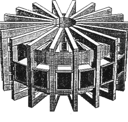
The stand (Fig 2.5) is 127.75" high and 172" in diameter, it consists of eighteen
4"X 6" radial I-beams 65" long which are aligned 200 apart and suspended between
the inner support ring and vertical legs of the stand. Each of these 20' wedges are referred to as a "section" of the VTF, with the section being labeled by the degree mark between the two radials. The angular labels start at the northern part of the machine (0*) and increase in a clockwise direction looking down on the machine.
The inner part of the radials are bolted to the 18 tabs welded on the inner support ring (Sect 2.2) and insulated from the ring with 1/2" G-10 plates. All of the radial beams are connected to their neighboring beams at the outer radius by
23" long cross-beams, which are also 4"X 6" I-beams. The outer joints (where the
radials, vertical legs and cross-beams meet) are made of two 1/2" thick G-10 plates bolted to each of the four beams as shown in figure 2.6.
On 14 of the 18 radials, the toroidal field coils rest upon two pads bolted to the top of the radial. These pads are made of 4"X 4" I-beams 7.5" long with a 1/4"
G-10 plate epoxied on top. Since these pads were located 23.375" and 58.625" from
the center line of the machine, their effect is to distribute the weight of the coils closer to the inner support ring and vertical support leg. This redistribution reduces the deflection of the radial by changing the moment arm on the radial. The bolts which hold the pads to the radials were not electrically insulated because this would of required a larger hole to accommodate the insulation, which would of weakened the radial more than necessary.
TOP VIEW 270 2 3 48
70
VIEN 'L! 6 ID1 - RADIAL ARM 4 - INNER RING
2 -CHAMEEP/TOROUE CYL CROSS PIECE 5 -SUPPORT LEG
3 -JOINER PLATE 6 -LEG EXTENDED INTO TROUGH
Figure 2.5: THE SUPPORT STAND
outer ring members top view radial arm.-, I I
II
-~ IIII
G-10 connector side view stand legFigure 2.6: SUPPORT STAND OUTER JOINT
o
z
The four radials without pads are located at 300, 1500, 2100 and 3300. The
reason for not placing pads on these radials is that four of the coils came with legs installed on them, so they were bolted directly to the stand. The legs on these four coils are at the same radii as the pads and disassembly of one leg showed they are insulated and allowed some motion of the coil so the machine can breathe.
Of the eighteen vertical legs, fourteen are 4"X 6" I-beam 117.5" long, with 6"X 6"
aluminum plates, 3/4", thick welded to both ends so the legs could be bolted to cell floor and outer radial joints. The remaining four legs are 6" square, concrete filled box beams with plates welded to both ends to attach the legs to the radials and
cell floor. Two of the box beams, located at 10' and 350*, are sandwiched to the
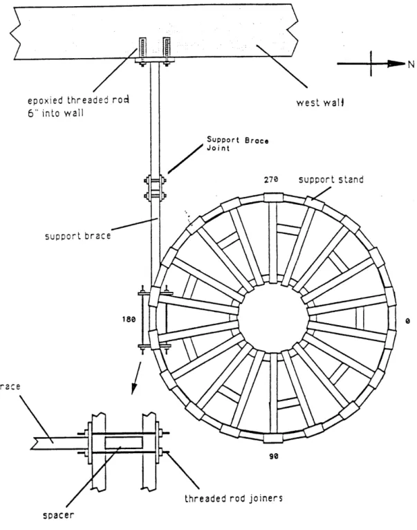
concrete block in the same manner as the support ring box beams (Sect 2.2.1). The remaining two box beams are located at 170* and 190' and are fastened to the west wall (Fig 2.7) to keep the stand from buckling in the event of an earthquake. The joint in the support brace was installed to raise the beam 2" because there was no clear path between this part of the stand and the wall (power supplies were in the way).
As mentioned above, the stand also supports the vacuum chamber and the outer torque cylinder. This was accomplished by the addition of nine cross-beams (Fig 2.5) made of 4"X 4" I-beams 22.25" long. These beams are bolted to the bottom of the radials at a 54" radius. The design of the vacuum chamber and torque cylinder
connection to these cross-beams can be found in Section 5.1.1.
Because the inner support ring and stand define the horizontal position of vir-tually every part of the VTF, they were constructed with precision. The radial and angular positions were determined using the three survey marks imbedded in the floor of the VTF cell. These three survey marks are aligned in the East-West direction, the center mark defining the center of the machine. The two other marks define the 90* leg (East of the center mark) and 270' leg (west of the center mark). In the final positioning of the stand, the base of the 90' and 270* legs were adjusted in both the radial and angular position to within 1/16 of an inch in radius and arc
epoxied threaded rod 6" into wall support brace -N west wall Support Brace Jai n t 270 support stand TJ 180 0 brace spacer thre 90
eaded rod joiners
Figure 2.7: SUPPORT STAND BRACING TO WEST WALL
length. These two legs were then positioned vertically to the same tolerance using a plumb line suspended from the top of the legs. Once these two legs were in place, the position of all the East (West) legs were adjusted using the 900 (270*) leg as a reference. Next, the heights of the TF coil pads on the radials were leveled to within
1/16" by shimming the legs between the base and the floor using the inner support
ring as a reference. Once this was completed, the entire stand was checked again to verify that the tolerances were met.
2.3.2
TEST AND LIMITS OF THE SUPPORT STAND
In general, each radial supports 1,400 lbs due to the vacuum chamber, outer torque cylinder and toroidal field coils. This load produced a calculated deflection of 0.04" on each radial [3]. To verify that the beams could withstand such a load, an on-site test of one beam was performed using a simple lever arm with students suspended from one end. The results showed that 8,200 lbs were required to produce a de-flection of 0.125", so the beams were considered satisfactory. As of this writing no measurable deflection of the radials has been noted with all the major components of the machine installed.
2.3.3
PROBLEMS WITH THE SUPPORT STAND
As a final comment on the stand, there are two problems that exist. The first is that one of the two threaded rods for the 2500 vertical leg started to pull out of the floor as it was being torqued. While the force required to pull the rod out is still large, it should eventually be removed and replaced.
The second problem is that in order to stabilize the machine during an earth-quake, the columns for the inner support ring and legs at the 0* section of the support stand were bolted to the concrete block, while the two legs at the 180* section of the stand were rigidly fastened to the wall of the cell. So if an earthquake should occur, and the wall and block move in different directions, the shear on the machine could reduce the magnitude of quake the VTF was designed to withstand.
Chapter 3
THE TOROIDAL FIELD
SYSTEM
As in any plasma device, confinement can be enhanced by the proper magnetic field geometry. The dominant field in the VTF is the toroidal field, which has a magnitude of 1 Tesla on axis. The toroidal field (TF) system described in this chapter will include the bucking cylinder, the toroidal field coils and the TF bus.
3.1
THE BUCKING CYLINDER
The purpose of the bucking cylinder, which was obtained from the University of Wisconsin, is to counter the centering force experienced by the TF coils. Since the bucking cylinder was previously used in a machine like the VTF, and we made no modifications to it, no design analysis or tests were performed for the cylinder.
3.1.1
DESIGN AND INSTALLATION OF THE
BUCK-ING CYLINDER
Once the VTF stand was complete, the Bucking Cylinder (BC) was the next com-ponent installed. The BC is an aluminum cylinder with an inner radius of 12", a nominal thickness of 2.25" and is 36.0625" high. It was assembled with a vertical
Phenolic electrical break in it and contains 18 vertically machined grooves in which
the noses of the TF coils fit. The grooves are located every 200 and are 4.03" wide
with a depth of 3/8". The BC is also beveled at the top and bottom so it fits snugly against the inner legs of the TF coils.
The BC was originally held in place by an iron pipe vertically mounted to the top of the concrete block. The pipe was centered above the vertical shaft of the block so the plumb line used to center the machine could pass through the pipe and block to the central survey mark on the cell floor. The pipe also had four bracket/bolt assemblies welded to the top so the BC could be rigidly positioned. The BC was adjusted in all dimensions to 1/16", and most measurements for the rest of the components (i.e., vacuum chamber, outer torque cylinder etc.) were taken from the cylinder because the the plumb line was not accessible with the cylinder installed. The BC's radial position was routinely checked against the plumb line during the construction of the VTF, and as of this writing the center of the BC is a little less then 1/16" North-West of the center survey mark.
The iron pipe supporting the BC will remain until the machine is pulsed at full power since this will help prevent the machine from "jumping" when the TF coils first experience a full centering force. After this, the pipe will be removed and the BC held up by 3 legs which were bolted to the sides of the cylinder between the grooves for the TF coils. The legs are fastened to the three tabs welded to the inner support ring (Sect 2.2) and are made of 3/4" stainless steel rods covered with a 1/8" thick G-10 tube for insulation.
3.1.2
TEST AND LIMITS OF THE BUCKING
CYLIN-DER
As mentioned above, no test or design analysis were performed on the bucking cylinder since its use in a similar machine demonstrated its structural integrity.
3.1.3
PROBLEMS WITH THE BUCKING CYLINDER
While it is not a problem, it should be noted that the joints where the legs are attached to the BC are not electrically insulated. The reason for not insulating these joints is that there was not enough room to drill a hole large enough to accommodate the insulation and still maintain the structural integrity of the legs.
3.2
THE TOROIDAL FIELD COILS
A total of 20 TF coils, at 1.5 tons each, were obtained from the University of
Wis-consin. Of these coils, 18 were used on the VTF and the remaining two considered a source of spare parts.
3.2.1
DESIGN AND INSTALLATION OF THE TOROIDAL
FIELD SYSTEM
A TF coil (Fig 3.1) consists of four turns made of copper bars with a 1"X 6"
cross-section and each coil has four joints held together by insulated Silicon-Bronze bolts. To cool the coils, each turn of each leg has a 3/8" diameter copper tube soldered to it. Prior to installation, each coil was inspected and repaired as necessary. These test consisted of a ring test, resistance test and visual inspection. Several of the TF coil cooling tubes were also hydrostatically tested and these test are described in Section 3.2.2.
Upon completion of the tests, 18 of the coils were positioned on the radial arms of the machine with three sheets of 10-mil mylar placed between the nose of the coils and the bucking cylinder for insulation. Once on the machine the tops of the coils were removed to facilitate the installation of other components and a tape measure wrapped around the perimeter of the machine to position the coils to within 0.1" using the 270* coil as reference. The final positions of the coils were then marked at the base of each coil and pad with a red marker so any movement can be quickly noticed. Table 3.1 contains the measured positions.
I ' ~~i~_-000 I..--I0. k..
I
.L~rt
000 - goo-1
-~ -W p4. 9 __Li
(I p -r r~I
I 9 uIIdk..i
)
-I',,). _ ' ' ____________I_( -0, _ -I-- M I-~~~~~O -. 1----.-.--. Iu T 1 -I "1 0 "TiTcOI~oIo&,. FIFL... Ca~t. A -. %V rLv Assy. P1to
0 . I I I I. I i K.
I I
I
. .. 1 9...!) -. [.-~.k.I.
.) .,.. (9 ... 4.!)II
I..!)jJ
rTOROIDAL FIELD COIL FINAL POSITIONING RESULTS (TABLE 3.1) TOROIDAL FIELD COIL (DEGREE) 10 30 50 70 90 110 130 150 170 190 210 230 250 270 290 310 330 350 IDEAL POSITION (INCHES) 91.275 114.097 136.917 159.736 182.556 205.375 228.194 251.014 273.833 296.653 319.472 342.292 365.111 387.931 0.00000 22.8190 45.6390 68.4580 MEASURE POSITION (INCHES) 91.188 114.156 137.000 159.813 182.620 205.313 228.125 251.000 273.781 296.563 319.500 342.250 365.063 387.937 000.000 22.8130 45.6250 68.5000 POSITION ERROR (INCHES) -0.09 +0.06 +0.08 +0.08 +0.06 -0.06 -0.07 -0.01 -0.05 -0.09 +0.03 -0.04 -0.05 +0.01 +0.00 +0.00 -0.01 +0.04 38
3.2.2
TEST AND LIMITS OF THE TOROIDAL FIELD
COILS
The coils were ring tested to check their inductance and the dampening. The test used an RLC circuit made of the TF coil, a 300 microfarad capacitor, a 1.5 volt battery and a Tektronix Storage Oscilloscope. The final values of the inductance measurements from the ring test and the corresponding resistances, after cleaning the fingers of the top two joints' with Scotch-Brite, tightening all the joints and installing the coils on the machine are given in Table 3.2.
One common problem found with the coils was that the two contact surfaces of the inner joints had a tendency to fail the resistance test (a total of 4 out of 18 coils failed). The location of the failures, as shown in Figure 3.2, are the two surfaces where parts 1 and 2 contact parts 4 and 5. The reason for these failures is not clear, but after a second cleaning of the inner joints the problem was eliminated. But to assume these joints were more susceptible to oxidation or cleaned less efficiently did not make sense since they are as accessible as all the other joints. So we cannot say at the moment what the real problem was, but it has not occurred again in any of the coils. Another common problem found was that the cooling tubes tended to short the coil turns since they are not electrically insulated from the turns. For
more information on the coil test see Reference
[4].
The visual inspection showed several areas where the external insulation of the TF coils were damaged. Repairs to the insulation were made by sanding and cleaning the areas with alcohol. The insulation was then replaced by filling the gouges with diced-up glass tape mixed in epoxy. Carbon deposits from previous shorts were also cleaned from the coils, so any deposits of carbon found on the coils will be from a short of our making.
The final inspection was the hydrostatic test of the cooling tubes. Initially, due to time limitations, it was decided not to connect the cooling system since it would not be necessary at low power and would consume a large number of man-hours. But a decision to go ahead and construct a full power machine, instead of upgrading
INDUCTANCE AND RESISTANCE TEST RESULTS OF THE
TOROIDAL FIELD COILS FOLLOWING REPAIRS (TABLE 3.2) NUMBER ON COIL WHEN RECEIVED 1 2 3 4 5 6 7 8 9 10 11 12 13 14 15 16 17 18 19 20 COIL POSITION ON THE MACHINE SPARE 10 350 SPARE 170 210 150 250 190 230 110 70 130 310 90 270 290 50 30 330 INDUCTANCE (pH) 36.6 37.7 36.5 37.7 36.1 36.1 36.1 36.3 36.0 37.0 36.3 35.3 36.0 37.4 36.1 36.0 38.7 36.1 36.1 36.7 RESISTANCE (m - Ohm) 0.36 0.16 0.16 55.60 0.16 0.16 0.16 0.16 0.16 0.20 0.16 0.17 0.16 0.16 0.17 0.16 0.16 0.16 0.16 0.19 ; ~)
I a
fi
I1
ON,) A".) I-...-, NO.. . 4 . CO C. C.mJJ (4 4) \. j ... ,. fl ..0--I .11
I-Inn
: : C. C A- A [- - -- a.c*=.. -. #: . J .A _ _ _ _ _-- -_H
I
-- CONS51UCTI.?-- -.7.0 L ;,!mo!, W" --1 cA 0 0 0 0ILn
Qs) 41 HI V- CC-ithe VTF at a later date, prompted us to think about cooling. Consequently, we decided to see how large the job was, and tested the cooling coils to estimate the amount of work required, since it would be easier to repair the cooling tubes during construction than to wait until the machine was assembled. But after hydrostatically testing several tubes to 100 psi with water, the failure rate of the tube fittings was so high (well above 60%) that the project was abandoned. While this decision will probably come back to haunt us, it is still possible to repair the outside and top cooling tubes of the TF coils since they are reasonably accessible. Such repairs would correspond to 50% of the total cooling capacity.
3.2.3
PROBLEMS WITH THE TOROIDAL FIELD COILS
The major concern with the TF coils are the cooling tubes, because, during the cleaning of the coils several of the carbon deposits were found near the fittings of these tubes. They stick out a few inches from the coils, and it would be very easy to accidentally nudge a tube close enough to another tube or component of the machine to cause an arc. Therefore, it is recommended that these tubes be insulated with shrink wrap.
One other possible problem with the coils is that several of the silicon/bronze bolts were missing when the coils arrived and were not replaced because it was cost prohibitive. This was justified because a survey of several Plasma Fusion Center and Magnet laboratory personnel produced no reason why we could not replace the silicon/bronze bolts with stainless steel bolts since the bolts are thermally and electrically insulated from the coil; so we did. The 30 or so bolts were shared among all the coils on the outer two joints for easy observation and accessibility should something go wrong. But upon reviewing this decision, it was realized that we did not take into account the elastic properties of the two different types of bolts. Therefore, it will be necessary to test a stainless and silicon bolt and then prevent the stainless bolts from taking a disproportionate amount of the force. This equal distribution of the forces can be accomplished by using compression washers on the
stainless steel bolts.
3.3
THE TOROIDAL FIELD BUS
The TF bus (Fig 3.3) consists of a supply bus running from TF coil to TF coil and a return bus to cancel the magnetic field made by the supply bus. The bus begins and ends at the 0' section of the machine.
3.3.1
DESIGN AND CONSTRUCTION OF THE TOROIDAL
FIELD BUS
The copper bars for the bus were salvaged from the outer torque cylinder when it arrived from the University of Wisconsin, so it has a lot of holes in it which serve no purpose. The bars have a 2.375"X 0.625" cross-section and the supply and return parts of the bus each consist of two of these copper bars. To minimize field errors, the buses were separated by 2" and bolted together using the G-10 insulated assembly shown in Figure 3.3. At 65 kAmps, this separation produces a magnetic repulsive force between the bus bars of 16,600 N/m which implies there are 11,200 N per
section of bus (1 section = 67.31 cm) or 1,883 N/bolt. Thermal expansion at 100*C
was calculated to produce a force of 8,097 N/bolt (App B.2) and the pre-torque was 11,104 N/bolt. So the total force on each of the four 1/2" bolts in the section is 21,084 N, which gives a safety factor of 2.1. The field error due to this separation was calculated to be 1 part in 1000 on the magnetic axis (0.9 m).
Prior to installing the copper it was cleaned in an acid bath and well rinsed, but in order to save time, we did not silver the contact surfaces on the bus. This decision was justified by the fact that low power operations only require 5 kAmps so silvering was not required. As far as preparations for high power operations, it will not be to hard to silver the bars since they are easily accessible.
Toroidal Field Coil flange
Water Cooling Channel G-10 Tbe0
6-10 (not used) 1 3/8 Cu Cu Cu Cu 5/8 [5/8 J 2
/
r /8 23/83/8 1/4 1/4 0 t-~1 ~J) C) 0 Lfl Cl) Cl) C) H /2 13/ 23.3.2
TEST AND LIMITS OF THE TOROIDAL FIELD
BUS
As far as temperature limits on the TF bus, 100*C was chosen to give a safety factor of 10 below the melting point of copper. It was also determined that at 65 kAmps the rate of the temperature increase is 23*C/sec (App B.1). This calculation was performed assuming that 32.5 kAmps passes through one copper bar with 1/2 of the area removed by a bolt hole. The reason for this area assumption is described in the next section.
3.3.3
PROBLEMS WITH THE TOROIDAL FIELD BUS
The problem with the TF bus is that in some areas the holes drilled in the center of the return bus to hold the supply and return together overlap the staggered holes the copper bars came with. This problem could not be avoided, so in some places the cross-section of one of the two copper bars is cut in half; but in no places are both bars like this. So when the bus is finally silvered, these contact points between the two bars of the return bus should also be silvered. It would also be a good idea to attach a thermo-couple at a few of these spots since they are covered with an insulating G-10 plate which may hinder cooling. There are no known problems with the supply part of the bus.
Chapter 4
THE INNER AND OUTER
TORQUE CYLINDERS
The inner and outer torque cylinders (Fig 1.1) were obtained from the University of Wisconsin, and both had to be modified to fit the VTF design. The purposes of the torque cylinders are to counter the over-turning force experienced by the toroidal field coils and to provide support for auxiliary coils.
4.1
THE INNER TORQUE CYLINDER
As mentioned above the inner torque cylinder helps counter the over turning force experienced by the TF coils. It is also used to support five coils which are part of the ohmic System (Sect 6.1). And, since modifications to this cylindez were slight, no calculations of the structural integrity were performed because the cylinder came from a machine similar to the VTF.
4.1.1
DESIGN AND INSTALLATION OF THE INNER
TORQUE CYLINDER
The inner torque cylinder (TC) is made of a fiberglass/epoxy composite 1.25" thick and has a outer diameter of 42" with a height of 38". There are 18 stainless steel
brackets located every 200 on the top and bottom of the TC. Each bracket contains two G-10 wedges which, when bolted down, clamp on to the TF coils and transmit the over-turning force of the TF coils to the TC. Also welded to the inner TC are
three legs at 200, 160', and 2800, the feet of the legs are bolted to the tabs on the
inner support ring (Sect 2.2).
The inner TC was installed prior to the vacuum chamber and fits like a skirt surrounding the inner legs of the TF coils. The brackets, which slide over the TF coils, had to be ground on the inner radius since they would not fit over the lower bend of the TF coils with all the insulation installed. To insulate the TC from the TF coils, three layers of 10 mil mylar were wrapped around the inner TF coil legs. To insulate the inner bends of the TF coils, three layers of mylar and two 1/16" G-10
plates were glued to the sides of each coil where the
G-10
wedges on the top andbottom TC brackets contact the coils. The plates provide a G-10 on G-10 sliding surface so the coils can "breathe" and they also help hold the mylar insulation to the bends of the coils.
4.1.2
TEST AND LIMITS OF THE INNER TORQUE
CYLINDER
The insulation between the TC and TF coils were tested to a 1.5 kvolt potential, and all discrepancies corrected.
4.1.3
PROBLEMS WITH THE INNER TORQUE
CYLIN-DER
There are two notable problems with the inner TC, and both have to do with the tight fit of the cylinder. First, to install the TC we had to use a substantial amount of force to push the cylinder over the inner legs of the TF coils. Therefore, we had to assume the TC was correctly positioned radially since we could not move it and we believe this was done carefully enough that none of the insulation was damaged.
But removal of the TC could be a tedious process unless the machine is "tightened up" by the centering force experienced by the TF coils. The reason this "tightening up" could ease the TC removal is that it may result in an increase of the clearance between the inner legs of the TF coils and the TC.
The second problem with the TC arose while installing the tops of the TF coils. Here it was noticed that the vertical clearance between the TF coils and the TC brackets at the top was much less then the vertical clearance at the bottom. In fact, one TF coil top could not quite be installed since we were afraid we would damage its insulation. So out of necessity, we decided to lower the TC 1/8" from its ideal position. The problem with this relocation is that the ohmic coil is also misaligned
by the same amount, but nothing short of revnding the coil could correct this, so
the error had to be accepted.
4.2
THE OUTER TORQUE CYLINDER
The purpose of the outer TC is to help counter the over-turning force of the TF coils and to support both the trim coils of the ohmic system (Sect 6.3) and two of the equilibrium field coils (Sect 7.1.1). As far as modifications to the outer torque cylinder, they were so severe that its ability to support the TF coils was questionable. So new methods of countering the over-turning force had to be devised and installed.
4.2.1
DESIGN AND INSTALLATION OF THE OUTER
TORQUE CYLINDER
The outer TC is made of a 1" thick fiberglass/epoxy compound, has an outer di-ameter of 108" and is 62.5" high and came in two parts, a lower and upper half, so that the vacuum chamber could be installed. And like the inner TC, the outer TC has 18 stainless steel brackets, with G-10 wedges, on the top and bottom so it can clamp on to the TF coils. Unlike the inner TC, which is constructed from one solid
2800 sections of the VTF. At the seams, the TC is held together by a sandwich of
fiberglass between two stainless steel plates. The inner plate is 5/8" thick and 5" wide while the outer plate is 1/2" thick and 5" wide. Both run the height of the
TC and are fastened together using 1/2" bolts. The reason for the use of two seams
in each half instead of one is unknown, but it may be related to fabrication cost instead of structural consideration.
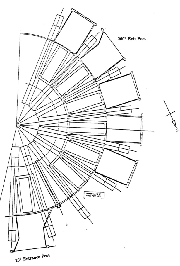
Due to the large size of the side ports, a substantial amount of material had to be removed from the outer TC to accommodate them, in fact, the TC is only 2" wide between these ports. Because of this reduction in the torque cylinder's structural integrity, modifications had to be made so it could counter the over turning force of the TF coils. These modifications include installing braces between the TC and vacuum chamber, bolting vertical straps between the side port openings of the TC and fixing large plates on the TC to counter the shear on the cylinder.
The braces (Fig 4.1) are 2"X 0.5" pieces of stainless steel bar stock, 16.25" long with two bends in them so they can be bolted flush to the outer TC and vacuum chamber. The bends are 190 and 8' respectively and are in opposite directions. The
9 pairs of braces on the VTF are used to transmit the over-turning force of the
TF coils from the stainless steel brackets on the TC to the vacuum chamber. The braces are attached to to the vacuum chamber via 5/8" stainless bolts welded to the ribs of the chamber (Sect 5.1.1), and are fastened to the TC brackets with two 1/2" stainless bolts. The braces are custom made for each TC bracket to ensure that there is no play in the system and there is one brace on all but two of the TC brackets. There are no braces at the 0* and 1800 sections because no material was removed from here since there are no ports at these locations. It is at these two sections that the plates, to be described later, were installed to connect the upper and lower TC halves.
The average force per brace is about 1/2 the total force on the top (or bottom) leg of a TF coil. For a TF coil current of 65 kAmps, a combined vertical and ohmic field of 0.26 Tesla (Sect 6.3.2) and a coil length of 1.35 m the total force is 22,800 N.