Design of a 50-Watt Air Supplied Turbogenerator by
STEVAN JOVANOVIC
Dipl6me d'Ing6nieur, Ecole Centrale Paris, France (2007)
Submitted to the Department of Aeronautics and Astronautics in Partial Fulfillment of the Requirements for the Degree of
Master of Science in Aeronautics and Astronautics at the
MASSACHUSETTS INSTITUTE OF TECHNOLOGY March 2008
© 2008 Massachusetts Institute of Technology All rights reserved
Signature of Author...
Department of Aero nacs and Astronautics March 7, 2008
Certified by... ... ... ...
N
Zoltn S.
S ovszky
H. N. Slater Associate Professor of Aeronautics an Astronautics Thesis Supervisor
Accepted by...
Prof. DLA L. Darmofal
MASSACHUSEITS 7NS E Associate Department Head
OF TEOHNOLOGy
Chair, Committee on Graduate Students
AUG 0 12008
Design of a 50 Watt Air Supplied Turbogenerator by
STEVAN JOVANOVIC
Submitted to the Department of Aeronautics and Astronautics
on March 7, 2008 in partial fulfillment of the requirements for the degree of Master of Science in Aeronautics and Astronautics
Abstract
This thesis presents the design of a high-pressure-ratio, low-flow turbogenerator with 50 W electrical power output, designed to operate from a 5-bar air supply. The research shows that a MEMS-based silicon turbine in combination with a micro-machined generator can meet the design objectives of the turbogenerator.
The turbogenerator architecture comprises a single-stage radial inflow turbine and a direct coupled cylindrical permanent-magnet synchronous generator. To address its key design trade-offs and fundamental engineering challenges, the design space is first explored in terms of the key design variables: device diameter and rotor shaft speed. To guide the selection of the two variables, a simplified model for the scaling of turbine and generator power is developed. Next, the integrated turbine and generator design is analyzed and designed in detail. The minimum manufacturable turbine blade span is identified as the key challenge imposed by the low flow requirement. Furthermore, the small scale of the blades results in high rotational speeds. Since the turbine and generator are integrated, the high speed makes the generator design challenging because of manufacturing tolerances, material stress limitations and losses. Thus, the design trade-off is between generator complexity and turbine blade manufacturability. The analysis shows that the viable low-flow 50 W turbogenerator design space is narrowly constrained by the minimum blade span and the 5-bar pressure supply, demanding MEMS fabrication for the short turbine blades.
A single-stage MEMS radial turbine is designed in detail, and assessed for performance and manufacturability. The rotor speed at design conditions is 450,000 rpm with a rotor radius of 5 mm, a rotor blade span of 200 um, and a blade tip clearance of 20 um. Based on 3D RANS simulations, the turbine is predicted to achieve 48% total-to-static adiabatic efficiency and to produce 77 W of shaft power at a turbine mass flow of 1.45 g/s. Assuming a generator efficiency of 80% and a power electronics efficiency of 90% yields a net electrical turbogenerator power output of 50 W. End-wall losses are dominant in the planar turbine and a diffuser is included to reduce the pressure losses in the right exit turn. The final high-speed, low flow design integrates a MEMS turbine and a meso-scale permanent-magnet synchronous generator combined with hybrid ball bearings.
Thesis Supervisor: Zoltdn S. Spakovszky Title: H. N. Slater Associate Professor
Acknowledgements
First and foremost, I wish to thank my thesis advisor, Professor Spakovszky, and Professor Lang. I thank Professor Spakovszky for his invaluable guidance and support. This work would not have been possible without his talent and deep care for the project. With his very high expectations and standards, he kept the project, and more importantly me, on tract. Despite his intense schedule, he was willing to help and contribute an incredible amount of time when necessary, even until the very end, even despite a small dog, a broken foot, and a trip to the emergency room. He was an example for me and for everybody in the lab. I wish to express my sincere appreciation to him. The success of this project was also due to the help of Professor Lang and his professional as well as personal guidance. His knowledge, friendliness and enthusiasm made all the difference. He could always spare the time and listen to any of my concerns. It was most pleasant to work with him.
My time at MIT was an invaluable experience. I learned the meaning of quality research; it was certainly a challenging time, but with the help of my advisors I learned enormous amounts in terms of rigor and logic, and how to challenge your results (which I had to do rather often!). My experiences at MIT marked me and changed the way I will approach new problems - what more can one ask to learn in Graduate school? For all this, I am vey thankful.
I want to thank as well everybody in the GTL for their help, advice and good times. This includes Professor Epstein, who initially gave the opportunity to work on this project, Diana Park, who helped with some of the graphs, Holly Anderson, who helped with all the organizational issues, and all my labmates who made my experience in the GTL worthwhile: Sean, Isabelle, Andreas, Bjmrn, and everybody else.
My journey at MIT would not have been possible without the love and support of my parents and brothers, and most importantly the unconditional love of Charity, who shared with me all the ups and downs.
Table of Contents
A cknow ledgem ents ... ... 5
Table of C ontents... 6 List of Figures... ... ... 8 L ist of T ables ... 11 N om enclature... 12 Chapter 1. Introduction... 14 1.1. Motivation ... 14 1.2. Turbogenerators... 14
1.2.1. Background and Concept... 14
1.2.2. Review of 5 - 500 Watt Turbogenerators and Turbines ... 15
1.3. Challenges for a 50 W Turbogenerator Design... 19
1.4. Research Objectives and Goals ... ... 20
Chapter 2. Turbogenerator System Analysis ... ... 21
2.1. Conceptual Layout of a Turbogenerator System... 21
2.2. Low Mass Flow Requirement ... ... 21
2.3. Design Requirements and Challenges ... ... 25
2.4. A ssessm ent M ethodology...26
2.5. System Architecture ... ... ... ... 26 2.5.1. Turbine A rchitecture... ... 26 2.5.2. Generator Architecture ... 28 2.6. Overview of Constraints... ... 29 2.6.1. Design Constraints... ... 29 2.6.2. Manufacturing Constraints ... ... 32
2.7. Turbogenerator Performance Assessment... ... 33
2.7.1. Scaling of Radial Turbines ... ... 33
2.7.2. Scaling of Cylindrical Generators ... ... 36
2.8. Turbogenerator Design Space Exploration ... ... 40
2.9. C onclusions ... ... ... 43
3.1. Design Point Selection and Proposed Design ... .. 45
3.2. Design Methodology ... 46
3.3. Mean-Line Analysis ... 47
3.4. Turbine Blade Profile Design... 49
3.4.1. Stator Blade (NGV) Design... 49
3.4.2. Rotor Blade Design ... 52
3.4.3. Turbine Stage Design ... 54
3.5. 3D Steady RANS Analysis... ... ... 55
3.5.1. Computational Domain and Passage Interface ... 56
3.5.2. Numerical Mesh ... 57
3.5.3. Diffuser Design ... 59
3.5.4. Convergence Criteria ... ... ... 60
3.5.5. Turbine Performance Analysis ... 61
3.6. Proposed 50 W Turbogenerator System... ... 65
3.7. Conclusions ... 66
Chapter 4. Conclusions and Recommendations for Future Work...67
4.1. Sum m ary ... 67
4.2. C onclusions ... ... 68
4.3. Future W ork ... 70
Appendix A. Numerical Mesh Sensitivity Study ... ... 72
Appendix B. Feasibility of Serial Configuration... ... ... 73
Appendix C. Low Speed Turbine Design... ... 76
List of Figures
FIGURE I-1: SCHEMATIC OF TURBOGENERATOR CONCEPT ... ... 14
FIGURE 2-1: SYSTEM LAYOUT OF THE PROPOSED TURBOGENERATOR SYSTEM. ... 21
FIGURE 2-2: CONVERSION OF COMPRESSED AIR TO USEFUL WORK ... ... 22
FIGURE 2-3: POWER DIVIDED BY MASS FLOW VERSUS TURBINE PRESSURE RATIO FOR DIFFERENT ADIABATIC TURBINE EFFICIENCIES, ASSUMING GENERATOR EFFICIENCY OF 80 %, POWER ELECTRONICS EFFICIENCY OF 90 % AND AN AIR INLET TOTAL TEMPERATURE O F 300 K ... 23
FIGURE 2-4: BLADE SPAN VERSUS TURBINE RADIUS FOR DIFFERENT MASS FLOWS, ASSUMING AN INLET TOTAL PRESSURE OF 5 BAR, A STATOR OUTLET FLOW ANGLE OF 75 DEG AND CHOKED FLOW FOR 50 W TURBOGENERATOR POWER OUTPUT... .... 24
FIGURE 2-5: ILLUSTRATION OF TRADE-OFF BETWEEN TURBINE CHALLENGE AND GENERATOR CHALLENGE AT CONSTANT TURBOGENERATOR POWER OUTPUT... ... 25
FIGURE 2-6: COMPARISON BETWEEN A RADIAL (LEFT) AND AN AXIAL TURBINE STAGE (RIGHT). ... .... ... 27
FIGURE 2-7: COMPARISON OF CYLINDRICAL (LEFT) AND PANCAKE (RIGHT) GENERATOR ROTOR CON FIG U RA TION S. ... ... 29
FIGURE 2-8: VELOCITY TRIANGLES FOR TYPICAL REACTION AND IMPULSE TURBINES. ... 30
FIGURE 2-9: SEM PICTURE OF A 4.2 MM DIAMETER SILICON ROTOR, 60 WATT TURBINE WITH 0.4M M BLA DE SPAN [26]... ... 33
FIGURE 2-10: SCHEMATIC OF RADIAL TURBINE STAGE ... ... 34
FIGURE 2-11: CROSS SECTION OF CYLINDRICAL GENERATOR. ... ... 37
FIGURE 2-12: ILLUSTRATION OF CIRCUIT DIAGRAM... ... 38
FIGURE 2-13: POWER OUTPUT VERSUS GENERATOR EFFICIENCY AT CONSTANT SPEED FOR GENERATOR REPORTED IN [37]...39
FIGURE 2-14: SYSTEM CHART FOR A TURBINE BLADE SPAN OF 300 UM AND 30 % ADIABATIC TU RBIN E EFFICIEN CY ... ... 40 FIGURE 2-15: 50 W TURBOGENERATOR DESIGN SPACE, ILLUSTRATING THE GENERATOR AND TURBINE SIZE, SPEED AND TIP SPEED CONSTRAINTS, AND THE HYBRID BALL BEARING SPE E D L IM IT ... 4 1
FIGURE 3-1: DESIGN TRADE-OFF BETWEEN ROTOR SPEED (GENERATOR STRUCTURAL
INTEGRITY) AND TURBINE BLADE SPAN (MANUFACTURABILITY LIMIT) ... 45
FIGURE 3-2: DESIGN METHODOLOGY. ... 46
FIGURE 3-3: FLOW DIAGRAM OF MEAN LINE METHOD... ... 47
FIGURE 3-4: VELOCITY TRIANGLES OF HIGH SPEED TURBINE DESIGN ... 48
FIGURE 3-5: WEDGE STATOR BLADE DESIGN [30]. ... 49
FIGURE 3-6: CAMBERED STATOR BLADE DESIGN [30]... ... 49
FIGURE 3-7: CP PROFILE OF STATOR BLADE ... ... 50
FIGURE 3-8: LOSS COEFFICIENT AND DEVIATION ANGLE AS FUNCTION OF STATOR SOLIDITY...51
FIGURE 3-9: TOP VIEW OF STATOR BLADE ROW ... 52
FIGURE 3-10: CP PROFILE OF ROTOR BLADE ROW... 52
FIGURE 3-11: LOSS COEFFICIENT AND DEVIATION ANGLE VERSUS ROTOR SOLIDITY ... 53
FIGURE 3-12: TOP VIEW OF ROTOR BLADE ROW ... 54
FIGURE 3-13: CONTOURS OF PRESSURE COEFFICIENT AT 50% BLADE SPAN ... 55
FIGURE 3-14: TOP VIEW OF HIGH SPEED TURBINE STAGE ... ... 55
FIGURE 3-15: GAS PATH GEOMETRY OF THE TURBINE STAGE... ... 56
FIGURE 3-16: COMPUTATIONAL DOMAIN DEFINITION...57
FIGURE 3-17: 3D VIEW OF ROTOR GRID (NOT ALL CELLS SHOWN) ... .... 58
FIGURE 3-18: 3D VIEW OF STATOR GRID (NOT ALL CELLS SHOWN) ... .... 58
FIGURE 3-19: TOP VIEW OF STATOR GRID WITH O TOPOLOGY, INCLUDING CLOSE UP OF THE LEADING AND TRAILING EDGE GRID... ... 59
FIGURE 3-20: NOMENCLATURE OF STRAIGHT CHANNEL DIFFUSER. ... 59
FIGURE 3-21: EFFECTIVE DIFFUSER FLOW AREA AND PASSAGE HEIGHT VERSUS RADIUS. ... 60
FIGURE 3-22: OVERVIEW OF LOCATIONS USED FOR PERFORMANCE AND LOSS ANALYSIS...61
FIGURE 3-23: LOSS BREAK-DOWN OF TURBINE STAGE ... ... 62
FIGURE 3-24: TURBINE PERFORMANCE ANALYSIS INCLUDING ESTIMATE OF TIP CLEARANCE LO SSES ... ... ... . . ... 63
FIGURE 3-25: VELOCITY VECTORS COLORED BY MACH NUMBER ILLUSTRATING FLOW IN INLET TURN, WITH INDICATION OF A SEPARATION BUBBLE ... ... 64
FIGURE 3-26: MACH NUMBER CONTOURS OF THE DIFFUSER FLOW... ... 65
FIGURE 4-1: EMERGING APPLICATION AREAS AND TRENDS FROM POWER MEMS AND TURBOMACHINERY [19] AND COMPARISON OF MIT TURBOGENERATOR. ... 70 FIGURE 4-2: DIAGRAM OF THE LJUNGSTREAM STEAM TURBINE; THE TWO ROWS OF BLADES COMPRISING EACH OF THE STAGES ROTATE IN OPPOSITE DIRECTIONS SO THAT THEY CAN BE BOTH REGARDED AS ROTORS, FIGURE ACCEPTED FROM [7] ... 71 FIGURE B-1: SCHEMATIC OVERVIEW OF ALTERNATIVE TURBOGENERATOR CONFIGURATION..73 FIGURE B-2: H-S DIAGRAM FOR SERIAL TURBOGENERATOR CONFIGURATION ... 73
FIGURE B-3: CONTOUR PLOT OF TURBINE SHAFT POWER FOR DIFFERENT PERCENTAGES OF WORK EXTRACTION AND INITIAL LOAD POWERS ... ... 74 FIGURE B-4: CONTOUR PLOT OF TURBINE RADIUS OF AN AXIAL TURBINE FOR DIFFERENT PERCENTAGES OF LOAD WORK EXTRACTION AND INITIAL LOAD POWERS ... 75 FIGURE C-1: LOSS BREAK-DOWN OF LOW SPEED TURBINE DESIGN ... 76
List of Tables
TABLE 1-1: SUMMARY OF 5-500 W SINGLE-STAGE RADIAL TURBINES FOUND IN THE
LITERA TU RE ... 15
TABLE 1-2: SUMMARY OF 5-500 W TURBOGENERATOR UNITS FOUND IN THE LITERATURE ... 16
TABLE 3-1: SUMMARY OF HIGH SPEED TURBINE DESIGN ... ... 48
TABLE 3-2: SUMMARY OF NON-DIMENSIONAL TURBINE STAGE CHARACTERISTICS ... 48
TABLE 3-3: COMPARISON OF MIT TURBOGENERATOR DESIGNS WITH TURBOGENERATOR UNITS FOUND IN LITERATURE. ... ... 66
TABLE A-i: VARIATION OF STATOR LOSS COEFFICIENT WITH STATOR GRID DENSITY. ... 72
Nomenclature
Roman
CP specific heat at constant pressure
C absolute flow velocity
h blade span, specific enthalpy
L length
rh mass flow
M Mach number
n number of pole pairs, number of blades
R radius p pressure P power s entropy SF safety factor T temperature, torque U rotor speed w specific work
W relative flow velocity
Greek
a flow angle in absolute reference frame
P3 flow angle in relative reference frame
y specific heat ratio
A finite change or difference
r efficiency
v Poisson coefficient
P density
in pressure ratio
o shear stress, solidity, stage reaction
r temperature ratio flow coefficient 'P work coefficient 0 shaft speed Superscripts ad adiabatic Subscripts
Exit turbine exit
n normal
PE power electronics
s static
t total
T turbine
tip rotor tip
Acronyms
DRIE Deep Reactive Ion Etching
SDM Shape Deposition Manufacturing
Chapter
1.
Introduction
11.
Motivation
This thesis investigates the design of a 50 W turbogenerator for which air is supplied at
5 bar. The major design goal is low mass-flow consumption for fixed turbogenerator power output, equivalent to high specific work and efficiency, since compressed air is considered a precious resource. Additional considerations are the simplicity of the design and the manufacturability of the components. The objectives of this thesis are to explore the design space and to define a viable turbogenerator architecture meeting the performance goals, manufacturing constraints, and tolerance requirements.
1.2.
Turbogenerators
1.2.1.
Background and Concept
A possible replacement for electrical power supplies is to employ a turbogenerator that converts compressed air, available from a pressure line or tank, into electrical power. In this context, a turbogenerator, as illustrated in Figure 1-1, is used to convert the energy stored in the fluid into mechanical work, and to convert mechanical work into electrical work. There are several methods of extracting the energy stored in compressed air, but most commonly a turbine is used because of its simplicity and relatively higher power density. To transform mechanical work into electrical power, an electric generator can be used.
Figure 1-1: Schematic of Turbogenerator concept. Turbogenerator
(air turbine coupled to a generator)
1.2.2.
Review of 5
-
500 Watt Turbogenerators and Turbines
Turbogenerators with power outputs in the kilowatt range can be found for example in Auxiliary Power Units and Micro Gas Turbines. On a much smaller scale (10 mm or less in diameter) MEMS based turbines have been extensively investigated and developed to produce shaft power in the 10 W to 100 W range. A summary can be found in Jacobson and Epstein [15]. In order to achieve high power density, these devices need to operate at high rotational speeds (of order million rpm). This yields a major challenge for bearings and rotor dynamics and requires high-speed gas bearings. For a summary see Liu et al. [21]. An alternative approach to small scale turbomachinery is to use micro-machined components. The tables below summarize both MEMS-based micro-scale and meso-scale conventionally manufactured turbogenerator and turbine designs. A short summary of the relevant work is given next.
Table 1-1: Summary of 5-500 W single-stage radial turbines found in the literature
Reference Pshaft (W) AI (g/s) Tti (K) X (-) 0 (rpm) IT (%)
MIT [26] 491 0.29 1,600 2.1 1,200,000 54
Stanford [33] 72 2.1 300 2.1 420,000 60
IHI [13] 3441 13.4 393 4 870,000 20
1
Performance at design speed; no experimental data published to date2
Table 1-2: Summary of 5-500 W turbogenerator units found in the literature
Pshaft Pel rk Ttl n n T
Reference Properties
(W) (W) (g/s) (K) (-) (rpm)
(%)
Off-the-shelf axial MIT/GIT [1] 10 8 N/A 300 2.1 305,000 N/A turbine coupled to
MEMS generator
Custom designed axial
KUL [25] 28 16 2.9 300 1.8 100,000 18 turbine coupled to
commercial generator Custom designed generator coupled to ETH [20] 250 150 4.0 300 3.5 500,000 70 off-the-shelf radial turbine
Three separate studies, at MIT, Stanford, and Tohoku University, focused on the design of single-stage radial turbines in the 50 W to 500 W range. As part of the Micro-Engine Project at MIT [26], a team developed a single-stage radial turbine with a 400 um blade span and a 6 mm diameter. At design conditions, this turbine produces 49 W of shaft power at a pressure ratio of 2.1. The challenge of fabricating the planar turbine with small features was addressed using deep reactive ion etching (DRIE), a fabrication method commonly used in computer chip manufacturing.
A team at Stanford University [33] designed and fabricated turbomachinery components for a miniature gas turbine engine. The single-stage radial turbine with a 12 mm diameter and a 250 um blade span was operated at 420,000 rpm. This air supplied turbine produced 72 W of shaft power. To address the challenge of high speed operation, hybrid ball bearings were used [24]; these hybrid ball bearings were tested separately up to 800,000 rpm. Here, the challenge of fabricating the aerodynamically designed components with small features was addressed using a mold shape deposition manufacturing (SDM) process.
At Tohoku University [13], research was conducted on demonstrating a 100 W gas turbine. As part of this effort, a miniature radial turbine was designed and fabricated. The
operation of the turbine was demonstrated as part of a turbocharger unit. The challenge of operating at high speed was addressed using hydro-inertia gas bearings [13]. 5-axis micro-milling technology was employed to fabricate the 3-dimensional turbine blades, required to achieve high efficiency.
Table 1-2 summarizes the characteristics of the turbogenerator units found in the literature that produce electric power approximately in the 1 W - 100 W range. The teams at MIT/GIT and at KUL utilized an axial turbine. The MIT/GIT team coupled an off-the-shelf dental drill turbine with a custom designed axial-flux permanent-magnet synchronous MEMS generator. This turbogenerator demonstrated a net electric power output of 8 W at 305,000 rpm. The main challenges of containing the brittle rotor magnet material, and maximizing generator rotor speed, were addressed by a tight-fit containment hoop and by choosing samarium cobalt (SmCo) as magnet material. The challenge of implementing a compact stator winding was addressed by electroplating the winding in place using MEMS fabrication technologies. The team at KUL coupled a custom-designed axial turbine to an off-the-shelf generator and tested this up to 160,000 rpm, generating 16 W electrical power output. The low pressure ratio, 10
mm diameter axial turbine design resulted in high blade profile losses and high exit losses. The main challenge of manufacturing the axial turbine was addressed by using an electro-discharge machining (EDM) process.
A team at ETH, Switzerland, designed and fabricated a 100 W, 500,000 rpm generator, which was coupled to a 10 mm diameter micro-machined off-the-shelf radial turbine with a 590 um blade span. This turbogenerator was operated at 490,000 rpm, with 150 W net electric power output. The main challenge of reducing generator losses at high speed operation was addressed by optimizing the winding design and the stator core material. Rotor integrity at high speed was ensured by employing a titanium sleeve containing the magnet core.
Important to note is that the 50 W to 100 W turbine powers are achieved at pressure ratios near 2. The research in this thesis is aimed at designing a turbine at similar power levels but at pressure ratios of 5 - 6. This yields a major challenge in the turbine design which is the focus of this thesis. Four common themes can be identified from the previous work.
Generator choice and design: The generator of choice is a permanent-magnet synchronous machine. Furthermore, generator rotor integrity at high speed requires a containment hoop to reduce centrifugal stresses in the brittle rotor magnet material. Only
custom designed generators with containment hoops are able to achieve speeds above 100,000 rpm [16]. At high speed operation, rotor and stator losses require a design optimization, and an appropriate choice of the material.
Bearing technology: To ensure high speed operation, either hybrid ball bearings [24] or air bearings are used, as reported in [13], [21] and [32]. The trade-off is between the simplicity and availability of hybrid ball bearings and the longer lifetime of air bearings. For a given rotational bearing technology, the maximum speed that bearings can support depends on the
DN number, where D is the diameter of the bearing (in mm) and N is the rotation rate in rpm. Conventional ball bearings achieve DN numbers of 2,000,000 to 3,000,000. High speed hybrid bearings manufactured by Myonic [24] can achieve DN numbers as high as 4,000,000. These bearings have higher DN numbers than their conventional counterparts because their ceramic balls match the ring material, the cage design reduces energy loss in the bearing, and dry lubrication minimizes the need for external lubrication. Air bearings provide an alternative option. They levitate the rotor by air pressure, either generated with an external supply (hydrostatic bearings) or by the motion of the rotor (hydrodynamic and air foil bearings). They have low friction losses and a longer lifetime. The disadvantage is that they are not yet commercially available. The details of an advanced micro gas bearing design can be found in
[32]. For the speed range required here, hybrid ball bearings are preferable due to their simplicity. Thus, the turbogenerator design in this thesis will adopt existing hybrid ball bearings.
Turbine manufacturing technology: The minimum feature size is critical, and set by the manufacturing technology. Three technologies have been demonstrated successfully: micro-milling, SDM, and DRIE, yielding minimum feature sizes of 300 um, 200 um, and 10 um respectively. The 1 W to 100 W power range is at the intersection of two trends: existing meso-scale designs are meso-scaled down by advancing conventional manufacturing technologies, and power MEMS are scaled up using new manufacturing technologies. While demonstrated technology is preferable when reliability is a design goal, certain constraints may require a new approach. Applied to the design problem studied in this thesis, the following conclusions can be drawn. The generator has to be custom-designed, and a meso-scale generator is preferable to a MEMS generator due to the higher demonstrated maximum rotor speed. Furthermore, the
minimum turbine blade span manufacturability limit imposed by micro-milling requires a MEMS manufacturing technology for smaller blade spans.
Turbine architecture: The options are single-stage versus multi-stage turbine, and radial versus axial flow machines. Most turbines are of the single-stage, radial inflow type. The radial turbines can operate at higher pressure ratios than the axial turbines and yield less complexity, as will be discussed in Section 2.5.1.
1.3.
Challenges for a 50 W Turbogenerator Design
The blade manufacturability constraint and low turbine mass flow at high pressure ratio requirement constrain the turbine design and pose an unconventional turbomachinery problem. Moreover, the integrated generator design yields a challenging system design problem, since generator stress limitations ask for a low-speed design, whereas the low turbine mass flow and manufacturing considerations require a high speed design. The design requirements and considerations can be summarized as follows.
Minimum mass flow consumption: To minimize consumed mass flow for a 50 W turbogenerator power output, high specific turbine work is desired. This requires high turbine pressure ratio and turbine adiabatic efficiency, and a relatively low flow area. To achieve the required turbine tip velocities while relieving the blade span constraint, high turbine shaft speeds are desired.
Turbine manufacturing constraints: The minimum feature size is set by the choice of manufacturing technology. The critical feature size is the blade span and in light of the low' mass flow requirement, MEMS based approaches using DRIE become attractive.
Generator centrifugal stress: Since an integrated generator and turbine have the same shaft speed, the maximum allowable turbine speed is constrained by the allowable generator centrifugal stress limit. Thus, lower shaft speeds are desired. It is evident that the generator and turbine design considerations yield opposite trends, making the integrated turbogenerator design a challenging endeavor.
1.4.
Research Objectives and Goals
The goals of this thesis are to explore the design space for a 50 W turbogenerator, to determine the major constraints and design trade-offs, and to carry out an in depth analysis and the design of a turbogenerator. The 50 W design requires a mass flow as low as possible while maintaining a supply pressure of 5-bar. Chapter 2 presents the turbogenerator design space and a first-principles based analysis combined with empirical correlations to identify the limiting technologies and major trades between the turbine and generator design. Chapter 3 presents the design of a high specific-work, low specific-flow radial turbine required to meet the design goals and details a high-fidelity assessment of the turbine performance using 3D CFD. Chapter 4 summarizes the key findings and the recommendations for future work.
Chapter 2.
2.1.
Turbogenerator System Analysis
Conceptual Layout of a Turbogenerator System
The proposed turbogenerator system consists of the major elements shown in Figure
2-1: a shut-off and throttle valve, a turbine that drives a generator, power electronics, a control
system, and a muffler to quiet the exhaust air. The shut-off and throttle valve modulate the air flow to the turbine and set the turbine inlet total pressure, which in return determines the useful turbine work and the turbine mass flow. The power electronics transform the output of the generator to a form compatible with the load, while the control system modulates the air according to the power demand and ensures safe operation.
Mass
flow
Turbogenerator system
Air supply Mass
flow
Muffler
Power -1
Exhaust
to ambient
Figure 2-1: System layout of the proposed turbogenerator system.
2.2.
Low Mass Flow Requirement
In this section, the low mass flow requirement and its design implications are discussed in detail. First, through a zero-order thermodynamic analysis, the required system characteristics are investigated. Second, the targeted mass flow range is identified as a function of efficiency and pressure ratio. Third, for the low mass flow requirement, the necessary
turbine dimensions and design features are assessed, identifying the key turbine limitation, blade manufacturability.
Figure 2-2 shows the process of converting the energy stored in compressed air to useful work employing thermodynamic coordinates in an enthalpy-entropy diagram. The change in stagnation enthalpy, Aht, is equivalent to the specific shaft work of the turbine, the useful work. The change in entropy, As, indicates dissipation and irreversibility, the lost work. As Figure 2-2 indicates, the throttle valve reduces the available work by decreasing the total pressure, creating entropy. Downstream of the valve, the turbine extracts useful work from the compressed air. Due to irreversibilities in the turbine during the expansion process, entropy is generated, which further reduces the useful work. Thus, given a turbine design and technology, the highest turbine pressure ratio should be utilized in order to maximize useful work and to minimize lost work. Ideally, the throttle valve should therefore be operated only as a safety shut-off valve. For a set power demand, reducing consumed mass flow is equivalent to increasing specific work, so a low mass flow is equivalent to high efficiency. This yields the following design implications. First, component efficiency must be maximized. Second, since the air must not be throttled, the turbine must be designed to operate at the highest possible pressure ratio.
w sefulwork
Entropy, s
From the 1st law of thermodynamics and the definition of adiabatic turbine efficiency,
the net electric power output of the turbogenerator can be written as a function of mass flow, component efficiencies, and turbine total-to-static pressure ratio as
ad 1- r
Pou,el =r--Wt= -•h .Tc-p.Tt,2 •- 1-PRt,_1-S .r77GE
*TPE
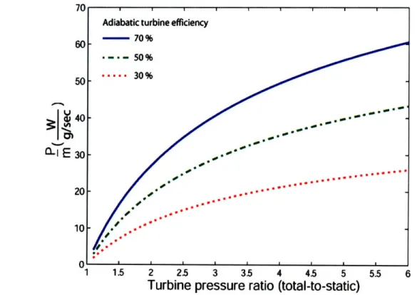
. (2-1) Based on Equation (2-1), Figure 2-3 shows contours of specific work (power divided by mass flow) as a function of turbine efficiency and turbine total-to-static pressure ratio. In this analysis a generator efficiency of 80 %, a power electronics efficiency of 90 %, and an air inlet total temperature of 300 K are assumed, typical for a device operating near the 50 W power level. More details can be found in Section 2.7. Figure 2-3 can be utilized to determine the mass flow for a set amount of turbogenerator power, pressure ratio and turbine efficiency. For a given power output of 50 W and a 5:1 pressure ratio, the mass flow ranges between 1 and 2.5g/s for 70 % to 30 % adiabatic turbine efficiency. The required mass flow will have an important impact on turbine blade design.
Turbine pressure ratio (total-to-static)
Figure 2-3: Power divided by mass flow versus turbine pressure ratio for different adiabatic turbine efficiencies, assuming generator efficiency of 80 %, power electronics efficiency of 90 % and an air inlet
total temperature of 300 K.
For a radial inflow turbine, the flow area can be written as
A = 27r -R -h, (2-2)
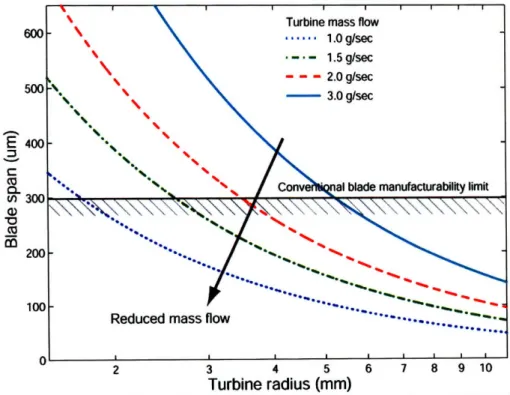
where R is the turbine radius and h is the blade span. Hence, for constant flow area, the blade span decreases as turbine radius increases. Assuming an inlet total pressure of 5 bar, a typical stator outlet flow angle of 75 degrees (high specific work) and choked flow, Figure 2-4 depicts the resulting blade span for different turbine radii and mass flows for a turbogenerator power output of 50 W. Furthermore, the minimum blade span for micro-milling manufacturing is indicated as a solid line. For a mass flow of 1 g/s and a turbine radius of 2 to 10 mm, the blade span ranges between 50 and 250 um. The analysis shows that the combined requirement for 50 W power output and low mass flow yields turbine blade spans below the conventional blade manufacturability limit for turbine radii larger than ~2 mm. Hence, an alternative manufacturing technology is required for a low flow, 50 W turbine. Two MEMS manufacturing options are discussed in Section 2.6.2, mold SDM and DRIE. Furthermore, this implies that the low ratio of blade span to turbine diameter yields turbine designs with increased end-wall losses, reducing the adiabatic turbine efficiency.
E
co C co 75 2 3 4 5 6 I u 1U Turbine radius (mm)Figure 2-4: Blade span versus turbine radius for different mass flows, assuming an inlet total pressure of 5 bar, a stator outlet flow angle of 75 deg and choked flow for 50 W turbogenerator power output.
2.3.
Design Requirements and Challenges
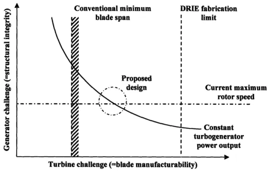
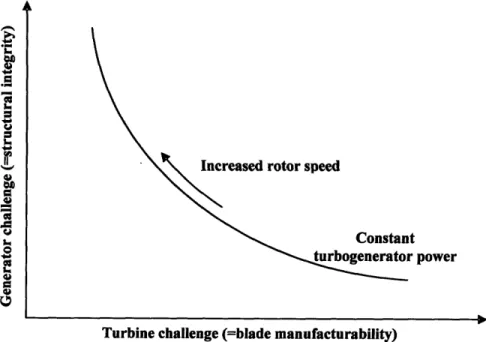
The primary challenge is the integrated turbine and generator design. The analysis carried out in Section 2.2 shows the following. To achieve a low mass flow for a set demand of turbogenerator power output, the turbine specific work must be high and the flow should not be throttled, taking advantage of the high pressure ratio of the air supply. Furthermore, the conventional micro-milling process imposes a blade manufacturability limit. For a constant flow area, the blade span is increased at lower turbine radii, and, for a given turbine architecture, the high specific turbine work requires a certain tip speed to meet the shaft power requirement. Thus, small turbine radii yield high shaft speeds. However, generator rotor balancing, mechanical stress and bearing considerations limit the maximum generator speed. High generator speeds require additional design efforts, as detailed in Section 2.7.2. Therefore, the integrated turbine and generator design must balance the blade manufacturability and generator speed constraints: the higher the rotor shaft speed, the less challenging the turbine design and the more challenging the generator design, and vice-versa. Figure 2-5 illustrates the relationship between structural integrity considerations and blade manufacturability.
1 I."
o
0 0,
Turbine challenge (=blade manufacturability)
Figure 2-5: Illustration of trade-off between turbine challenge and generator challenge at constant turbogenerator power output.
k
h-2.4.
Assessment
Methodology
The challenge is to design an integrated turbogenerator system. Since turbine and generator are on the same shaft, torque and angular speeds are identical; this tightly couples their aerodynamic and electromagnetic design. First, based on first principles, the system architecture is discussed and investigated with respect to the design requirements. Next, the major constraints on the component architectures are identified. Then, an analytical model along with suitable approximations is given to scale the performance as a function of design. The two sets of design constraints and scaling laws are combined to investigate the integrated turbogenerator system. Finally, the insight gained is discussed and a preliminary design is presented.
2.5.
System Architecture
To begin its development, the system architecture is discussed in this section based on first principles. The turbine architecture selection criteria are based on low specific-flow, high specific-work, blade manufacturability, turbine adiabatic efficiency and mechanical simplicity. The generator architecture selection criteria are efficiency, compactness and structural integrity at high speed. The goal is to define a system architecture that best meets these individual requirements.
2.5.1. Turbine Architecture
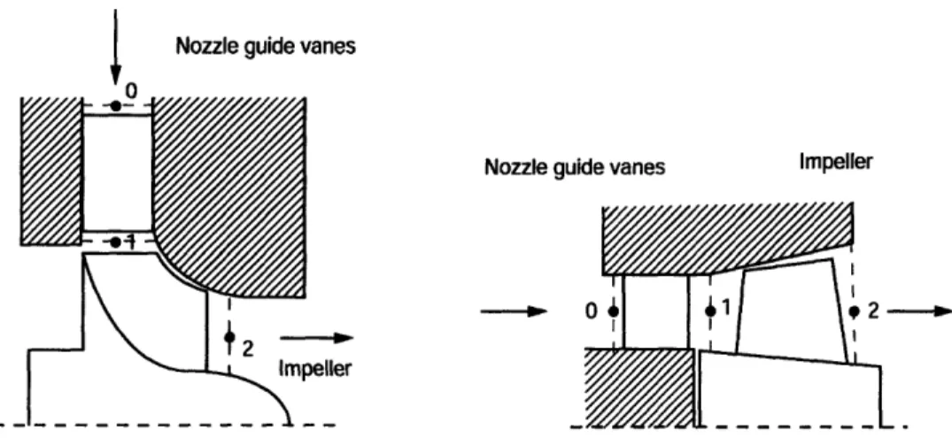
There are two distinct turbine architectures possible for this application: a radial inflow turbine or an axial flow turbine, as illustrated in Figure 2-6.
4
Nozzle guide vanesNozzle guide vanes Impeller
Figure 2-6: Comparison between a radial (left) and an axial turbine stage (right).
In comparison to axial turbines, radial inflow turbines have multiple advantages. Radial turbines have a smaller inlet area for the same rotor diameter due to their reduced blade span to tip radius ratio. A typical axial turbine hub-to-tip ratio of 0.4 to 0.6 results in a larger blade span than in a typical radial turbine where the blade span-to-tip radius ratio is typically 0.1 to 0.3 [28]. Hence, radial inflow turbines are preferable for low specific-flow applications. As detailed in Section 2.7.1, Euler's turbine equation links specific shaft-work and velocity triangles through
S2
12-22
22
(2-3)
where U is the rotor speed, C is the absolute velocity, and W is the relative velocity. Station 1 is at the rotor inlet and station 2 is at the rotor outlet. For axial turbines, where changes in mean-line radius are negligible and hence U, ; U2, little or no contribution to the specific
shaft-work is obtained from the centrifugal effect captured in the first term. However, for radial turbines, where U1 > U2, the change in rotor velocity contributes significantly to the specific
work. Hence, radial turbines achieve a higher pressure ratio for the same rotational speed due to the centrifugal effect [7]. Thus, radial turbines are preferable for high specific-work applications and are used when a more compact power source is needed.
In addition, radial turbines are relatively simple to manufacture (typically single cast) and robust [30]. In axial machines, the blade angles over the blade span vary if the work coefficient is kept constant. Hence, blades in an axial machine are twisted and require special
manufacturing technology. This is deemed difficult to implement at the level of miniaturization required here. This judgement is corroborated by findings reported in [25] and [34].
The advantage of a multi-stage design is higher efficiency because rotor tip speed can be lowered for a set amount of specific work; the disadvantage of a multi-stage design is increased complexity. Since one of the goals here is to keep the design simple and compact, a single-stage is preferable in order to avoid complex rotor designs and large turbine diameter. As a consequence, a high specific-work coefficient is required.
An alternative axial design that would meet the work requirement is a high flow and low pressure ratio configuration, reported in Appendix B. To reduce the pressure ratio, the turbogenerator would have to be placed in series with another load. Due to the low pressure ratio across the axial turbine resulting from this configuration, the mass flow required to meet the turbogenerator power goal is much increased. Furthermore, ducting losses become an important consideration, and the overall design becomes inefficient.
In summary, a single-stage radial turbine is desired for this high pressure ratio, low flow 50 W turbogenerator application. The remainder of this thesis is focused on the detailed design of such a device.
2.5.2. Generator Architecture
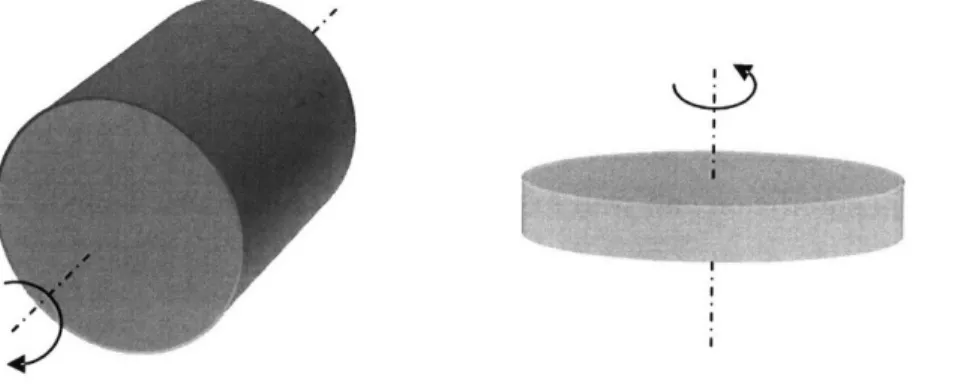
Permanent-magnet synchronous generators are more efficient and power-dense than other generators at small sizes because permanent magnets provide the same magnetic flux density independent of size, whereas it is increasingly difficult from a thermal viewpoint to produce a given flux density from a rotor winding as size decreases because Ohmic losses in the rotor windings require more cooling surface than is available. Two distinct generator
shapes are possible for this application: the traditional axial "cylindrical-shaped" rotor and the disk-shaped "pancake" rotor, as illustrated in Figure 2-7.
Figure 2-7: Comparison of cylindrical (left) and pancake (right) generator rotor configurations.
A cylindrical geometry is assumed so that all magnets are at the maximum lever arm, which makes the generator compact. In addition, this geometry places no magnetic load on the bearings. For cylindrical generators, centrifugal stress sets the maximum rotor tip speed. This tip speed can be increased by using a containment hoop. In the study reported here, a cylindrical permanent-magnet synchronous generator with a containment hoop is assumed.
2.6.
Overview of
Constraints
As part of the assessment, the major constraints of the turbine and generator architectures are identified in this section. The main design variables are turbine and generator diameter size and shaft speed as a function of turbogenerator power output. Manufacturing constraints and limitations are related to off-the-shelf availability of components and current manufacturing standards.
2.6.1. Design Constraints
Based on results from [2] and [33], it is hypothesized that, as the turbine gets smaller in diameter, there is a diameter for which the flow transitions from turbulent to laminar, such that turbine adiabatic efficiency deteriorates significantly. For the shaft speeds considered here, the critical turbine radius is approximately 1 mm to 3 mm. This estimate is corroborated by previous work on micro engines [14]. Thus, a 2 mm turbine radius will be assumed to be the minimum turbine radius in the study discussed here.
44-Based on the computational results presented in Appendix C, it can be concluded that the minimum allowable blade span is constrained by aerodynamic considerations. The study shows that a 100 um passage height, with an 80 um blade span and 20 um tip clearance gap in the rotor, results in significant end-wall losses, yielding a turbine adiabatic efficiency of 28 %. As previously outlined, a high component efficiency is desired, such that a 100 um tall gas path is assumed to be the limiting blade span.
The allowable centrifugal stress in the turbine rotor limits the maximum turbine rotor tip speed. Assuming an axisymmetric, solid rotating disc under elastic deformation, the limiting tip speed can be written as
(R 2
8
8.)
rmax (2-4)(3 + v) p
where a.. is the maximum mechanical stress, p is the material density, and v is the Poisson coefficient. The higher the strength-to-density ratio of the material, the higher the limiting tip speed. The tip speed is limited to 300 m/s for plastic, 500 m/s for aluminum and 700 m/s for titanium. However, efficiency considerations require sub-sonic turbine rotor operation; for cold air the tip speed should stay well below 330 m/s. Therefore, if silicon nitride or a metal is used, the turbine material stress limit is not a relevant constraint.
For example, assuming zero exit swirl, a flow coefficient of 0 = 0.5, and a constant
axial velocity through the stage, the work coefficient, W = w , for a typical reaction turbine
U2
equals one, and the work coefficient for a typical impulse turbine, or zero reaction turbine, equals two, as illustrated by the velocity triangles in Figure 2-8.
NGV Rotor NGV Rotor
0.
=0
'.5 "- =0.5Reaction turbine, ' = 1 Impulse turbine, T = 2
Using the 1st law of thermodynamics, the definition of turbine adiabatic efficiency and the
definition of work coefficient, the turbine pressure ratio can be written as a function of rotor tip Mach number, work coefficient and rotor efficiency
-l
PR
=[1 -
(2-5)2 rl d
To avoid shock losses, the stage should be operated well below sonic conditions. Tip Mach number of 0.9 and a turbine adiabatic efficiency of 50% are assumed to estimate the highest possible pressure ratio if a reaction turbine were used. This yields a turbine pressure ratio of 4.5. Thus, in order to operate at supply pressure ratios of 5-6 with a single-stage design, a low-reaction turbine design is required.
The generator length should be approximately five times the magnet thickness or greater otherwise the magnetic fields begin to fringe outward in the axial direction and the shear stress and efficiency decrease rapidly, as mentioned in [12]. Since the smallest allowable generator magnet thickness is assumed 800 um due to manufacturing constraints [18], the generator length becomes 5 mm. Because high component efficiency is required, this generator length is assumed to be the shortest possible generator length considered in this study.
For a generator without a containment hoop, the maximum rotor tip speed is limited by the allowable mechanical stress in the magnet material. Assuming an axisymmetric, solid rotating disc under elastic deformation, the limiting tip speed becomes
(R. 8 Omax (2-6)
(3+v)
p
where oma is the maximum allowable mechanical stress of the magnet material, p is the magnet material density, and v is the Poisson coefficient respectively. For a typical permanent-magnet material with p = 8,500gk , v = 0.3, and oa. = 25 MPa, the tip speed is
80 m/s. This is too low and so external containment is required.
The magnets can be contained within a containment hoop. In this case hoop failure limits the maximum generator rotor tip speed. This hoop must be much thinner than the magnets to preserve good magnetic performance. A detailed model to estimate the burst speed can be found in [31 ], but a first order estimate of the limiting rotor tip speed is
(R.
K2)2
< max,hoopHoop thickness
1
Pmagnet Magnet thickness SF'
written as a function of mass density of the magnet material (commonly Sm2Col7 or NdBFe depending on the temperature), and the strength and thickness of the hoop; SF is a safety factor. For a typical magnet density of 8,500 kg/m3, a required minimum hoop-to-magnet thickness
ratio of 1:8, a safety factor of 1.5, and a containment ultimate material strength of 1500 MPa for Kevlar, the limiting rotor tip speed is 120 m/s. For Inconel with a material ultimate strength of 2500 MPa, the limiting rotor tip speed is 155 m/s. For titanium with a material ultimate strength of 3500 MPa, a limiting rotor tip speed of 180 m/s can be achieved. The maximum tip speed in combination with the minimum generator rotor diameter determines the maximum shaft speed, which in turn is important for the turbine design because low turbogenerator flow considerations shift the design towards high rotational speeds.
The maximum allowable rotor magnetic shear stress is limited to roughly 35 kPa (5 psi) [22]. This limit depends on magnet properties, magnetic core saturation, and reasonable stator cooling limitations. The magnetic shear stress could be increased through forced air cooling to 70 kPa (10 psi) [22].
2.6.2. Manufacturing Constraints
Current manufacturing technology sets the minimum magnet thickness to approximately 800 um [18] for high strength magnets. Furthermore, the difficulty of assembling the magnets for small rotors sets the smallest possible rotor diameter to approximately 4 mm.
In a radial turbine, micro-milling manufacturing technology limits the shortest blade span to 300 um [34]. This is set by the manufacturing precision of micro-milling machines and structural integrity considerations set by the fillet radii at the blade root where stress concentrations can occur. Since conventional manufacturing methods limit the blade to 300 um, an alternative manufacturing approach is needed to enable shortened blade spans. The mold SDM process in combination with ceramic gel-casting can achieve feature sizes as small as 200 um [33]. Silicon etching technology offers a solution for blade spans below 200 um. Deep reactive ion etching (DRIE) technology was successfully used in the Micro-Engine Project at
MIT [14]. This process consists of placing a mask on a wafer, and removing the exposed material through etching. The etch depth and their profiles are controllable. The result is a planar geometry with two-dimensional features [14]. Figure 2-9 shows a scanning electron microscope (SEM) image of an etched silicon micro turbine, with a 4.2 mm rotor diameter and 0.4 mm blade span [26].
Figure 2-9: SEM picture of a 4.2 mm diameter silicon rotor, 60 Watt turbine with 0.4mm blade span [26].
In conclusion, both the turbine and the generator designs are constrained by rotor
diameter and shaft speed limits. Blade manufacturability and structural integrity considerations form the two major limitations of the design.
2.7.
Turbogenerator Performance Assessment
A 1st principles based model along with suitable assumptions is presented in order to
assess the turbogenerator performance as a function of the key design parameters: rotor shaft speed and device diameter at a set level of turbogenerator power output.
2.7.1. Scaling of Radial Turbines
A radial turbine is comprised of two major components: a set of stator blades (often referred to as nozzle guide vanes) and a set of rotor blades (often referred to as impeller blades), as shown in Figure 2-10. Two factors determine the shaft power output of a turbine: mass flow
and specific shaft-work. Both factors can be modeled as a function of rotor diameter and shaft speed. The goal here is to develop a set of scaling laws that can be used to explore the design space.
Nozzle guide vanes
mpeller
Figure 2-10: Schematic of radial turbine stage.
The corrected mass flow per unit area through a radial turbine can be expressed in terms of the inlet total pressure p, and total temperature T,, the flow area A, the specific heat ratio y, and the local Mach number M at the throat of the nozzle guide vanes as
t M
Sr+l
(2-8)P
-
A
( +1(+Y-I.M2.(
The flow area based on the rotor radius R and the blade span h is given by
A = 2 r -R h. (2-9)
For pressure ratios above the critical pressure ratio of 1.89, the flow is choked and Equation (2-8) simplifies to
=0.58. (2-10)
Pt "A
The mass flow per unit area is thus proportional to the inlet total pressure and the inverse of the square of the inlet total temperature. The flow coefficient 0, defined in Equation (2-11), can be written as
= , (2-11)
2n,.h.R.p.U
and can be related to the velocity triangles. At the rotor inlet, station 1, the flow coefficient becomes
C~
cos(a1)UA
=
cos(a)•ln(2-12)
Ul sin(ao) - cos(a 1) -tan(A)
Typical values for flow coefficients can vary from 0.3 to 0.7, as reported in [35].
From the 1st law of thermodynamics for steady, adiabatic flow, the specific shaft-work
is equal to the change in total enthalpy
w, = Ah,. (2-13)
For a calorically perfect gas, the change in total enthalpy is related to a change in total temperature by
Ah, = cP, ATt, (2-14)
such that, with the definition of turbine adiabatic efficiency
ad 1-r
r = - (2-15)
the change in total enthalpy then can be expressed as
Ah,=,ad
p{
[-Tt2t2].1
(2-16)
The change in enthalpy is a non-linear function of the pressure ratio across the turbine and increases with an increasing pressure ratio, everything else equal. Using the Euler turbine equation, the specific shaft work can be linked to the velocity triangles through
where Co is the tangential component of the absolute flow velocity and U is the wheel speed. The work coefficient is then defined as
wt
A(UCO)
= w= A(UC= ) (2-18)
U12 U12
where U1 is the wheel speed at rotor inlet. Assuming no exit swirl, and using relationships from
the velocity triangles, the work coefficient for an ideal rotor can be expressed in terms of the absolute flow angle a and relative flow angle
fl
at the rotor inlet according tosinla)1
sin(a,) (2-19)
sin(a,)- cos(aj ). tan(fl,)(
Typical values for the work coefficient of radial machines vary from 0.8 to 1.2, with 0.85 known to yield optimum efficiency in conventional single-stage radial inflow designs [3].
At small scale, end-wall boundary layers yield increased blockage and increased viscous losses. Typical small scale turbine adiabatic efficiencies can range between 20 % and 70 % as reported in [5], [13], [20], [25], and [33] for 4 mm to 14 mm diameter turbines. For now this study assumes 30 % turbine adiabatic efficiency, although, for 50 W operation of a planar turbine geometry, a 50 % turbine adiabatic efficiency can be expected as reported from computational results in [14]. High fidelity flow field computations are conducted on a candidate design to assess this assumption. These results are reported in Section 3.5.
2.7.2. Scaling of Cylindrical Generators
Building the axial-shaped generator from the rotor core outwards, there is first a steel core, then magnets, then optionally a containment hoop, then an air gap, and finally the stator core as Figure 2-11 illustrates. In this figure, it is assumed that the stator windings are set in the slots within the stator core, hence they are not shown. Since the main focus is on the scaling of generator power with speed and size, the stator scaling is not further discussed in this thesis because only the rotor dimensions interact with the turbine.
Magnet
Hoop
Air gap
Stator (slotted)
Figure 2-11: Cross section of cylindrical generator.
The power input P. of a permanent-magnet, cylindrical-shaped generator is the product of torque T and speed 0, hence
Pin = T.•. (2-20)
The torque produced by an cylindrical-shaped machine can be predicted to first order as the product of generator efficiency qGE, magnetic shear stress a, the active surface area and the
lever arm according to
T = irGE -. .(2. r R. L). R. (2-21)
Hence, the generator power output of a generator is
Pou, = 0-(2. '. R.L)-· R -r.GE. (2-22)
There are four major loss sources in the generator: Ohmic losses in the windings, eddy current losses in the windings of a slotless machine, eddy current losses in the stator core, and hysteresis losses in the stator core. All but the Ohmic losses result from a varying magnetic field caused by moving magnets; they are hence dependant on speed. Eddy current losses and hysteresis losses in the stator scale together typically as oc .8, and eddy current losses in the
windings of a slotless machine scale as oc 02.
Thus, it becomes increasingly difficult to design an efficient generator at higher speeds. To reduce losses at high speed operation, certain design measures are required: Litz wire can be used in the windings of a slotless machine, thin
laminations and ferrite can be used in the stator core, and a thick core made of ferrite can be used for the stator. Finally, the Ohmic losses can be reduced by using copper and optimizing the air gap size. If these requirements are met, the generator can be assumed to first order as 80% efficient even at high shaft speed and 50 W operation. This approximation is corroborated by results from [37]. The generator in [37] was designed for operation at 500,000 rpm and 100 W net electrical power output and incorporated all of the mentioned modifications, hence achieving 87 % efficiency.
If the very same generator were to run at 500,000 rpm, but 50 W, its efficiency will increase. To understand this, the generator is represented in a circuit diagram as a resistance in series with a load and power supply, as illustrated by Figure 2-12.
RG
VG
Pout
Figure 2-12: Illustration of circuit diagram.
The power output as function of generator resistance RG, load resistance RL and terminal
voltage VGE can be written as
Pout RGE + RL (2-23)
and the power input as
VG
Pm VGE VGE (2-24)
RGE + RL
Generator efficiency is defined as ratio of power input to power output
P R
7GE in
L+__
(2-25)
Pout RL + RGE
(1- r )
=
RGE (2-26)RL + RGE
Substituting the above equations into the definition of power output, the generator power output can be written as function of generator efficiency and the generator parameters phase resistance and terminal voltage
P
=(
GE qGE -qGE)RGE (2-27)
Thus, for a specified generator phase resistance and constant terminal voltage at constant rotor speed, the efficiency increases for decreasing power output, as depicted in Figure 2-13.
CL 0
a-
oo.
Figure 2-13: Power output versus
0
Efficiency [%]
generator efficiency at constant speed for generator reported in [37].
The expected electric frequency of the generator, based on the number of pole pairs and speed, defined as
oet = "-n, (2-28)
is on the order of 5 - 10 kHz. Efficient power electronics have been demonstrated for an
electric frequency of 20 kHz in [37]. Commonly, the power electronics efficiency is limited by cost rather than by physics. Hence, power electronics are assumed to first order as 90 % efficient.
2.8.
Turbogenerator Design Space
Exploration
The objective here is to investigate the relationship between the turbine and generator design and to explore the 50 W, low flow turbogenerator design space. The turbine and generator are connected through a common shaft such that both components have the same
shaft speed because a gear box is judged not to be a viable solution at the assumed size.
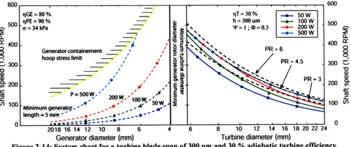
Figure 2-14 depicts the limitations of conventionally manufactured blades (limited to 300 um), and the effect of the desired turbogenerator power output level on rotor diameter and shaft speed. Two observations can be made. First, for a blade span of 300 um, it is not possible to achieve a 5:1 pressure ratio for 50 W turbogenerator power output. Second, as power increases, turbine pressure ratios of 5:1 become feasible. The key limitation is due to the low mass flow requirement and inherent blade span limitation. To relieve the blade manufacturing constraint, an alternative fabrication method is required for a 50 W, high specific-work turbine design. 0nn 600 500 400 , 300 u 200 (/ 100 500 400 300 C 200 u 100 0 0 2018 16 14 12 10 8 6 4 6 8 10 12 14 16 18 20 22 24
Generator diameter (mm) Turbine diameter (mm)
Figure 2-14: System chart for a turbine blade span of 300 um and 30 % adiabatic turbine efficiency.
The left-hand graph in Figure 2-14 displays contours of constant turbogenerator output power, derived from Equation (2-22), as a function of generator diameter and speed, assuming a shear stress of 5 psi, a generator efficiency of 80 %, a power electronics efficiency of 90 %, and a generator length of 5 mm. The generator design space is constrained by the smallest allowable generator rotor diameter dictated by manufacturing constraints and the maximum allowable generator rotor tip speed set by stress limitations in the containment hoop, derived
qGE = 80 %
iqPE=90%
o= 34 kPa
Generator containement '
hoop stress limit -• '
P=50OW,' 2
-' 1(2WW 1 Minimum generator - ' , -' 0 W length = 5 mm .. .. -- C~~=T---'S
i.
:I Efrom Equation (2-7). For a set turbogenerator power output and generator diameter, increasing the rotor speed would require a shear stress reduction, derived from Equation (2-22), while decreasing the speed would require additional generator length. For a set turbogenerator power output and constant generator shaft speed, decreasing the generator diameter would require additional generator length, while increasing the generator diameter would require a shear stress reduction.
The right-hand graph in Figure 2-14 describes a set of different turbine shaft powers for a single-stage, radial turbine (represented by solid lines). Assuming a turbine adiabatic efficiency of 30 %, a generator efficiency of 80 %, a power electronics efficiency of 90 %, a work coefficient of I and a flow coefficient of 0.3, the turbine design space is limited by three constraints at constant output: supply pressure ratio, blade manufacturability considerations, and smallest allowable turbine diameter.
Figure 2-15, analyzes in more detail the 50 W design space and the impact of different turbine manufacturing technologies, as well as the impact of different generator types. The turbine assumptions are consistent with high-fidelity simulation results presented in Chapter 3. The major observation is that in a narrowly constrained design space only a MEMS turbine near 500,000 rpm yields a viable 50 W, low flow turbogenerator design.
10 9 8 7 6 5 4 3 2 3 4 6 1 8 8 10 5 0• o o 0:
Generator radius (mm) Turbine radius (mm)
Figure 2-15: 50 W turbogenerator design space, illustrating the generator and turbine size, speed and tip speed constraints, and the hybrid ball bearing speed limit.
The left-hand plot in Figure 2-15 depicts the generator design space with and without the containment hoop constraint, derived from Equation (2-6) and Equation (2-7). Furthermore,
C:0

![Figure 2-9: SEM picture of a 4.2 mm diameter silicon rotor, 60 Watt turbine with 0.4mm blade span [26].](https://thumb-eu.123doks.com/thumbv2/123doknet/14683626.559733/33.918.299.642.328.563/figure-picture-diameter-silicon-rotor-watt-turbine-blade.webp)