Development of a Cold End and High-Efficiency Valves for a One-Watt 10 Kelvin Cryocooler
by
Matthew J. Traum
B.S., Mechanical Engineering (2001) B.S., Aerospace Engineering (2001)
University of California, Irvine
Submitted to the Department of Mechanical Engineering in Partial Fulfillment of the Requirements for the Degree of
Master of Science in Mechanical Engineering
at the
Massachusetts Institute of Technology June 2003 AASSACHUSETTS INSTITUTE MASSACHUSETTS INSTITUTE OF TECHNOLOGY
JU L 0 8 2003
LIBRARIES © 2003 Massachusetts Institute of TechnologyAll Rights Reserved
Signature of Author...
Matthew J. Traum Department of Mechanical Engineering May 9, 2003 Certified by...
John G. Brisson Professor of Mechanical Engineering Thesis Advisor
Accepted by... ...
Ain A. Sonin Chairman, Department Committee on Graduate Students
Development of a Cold End and High-Efficiency Valves for a
One-Watt 10 Kelvin Cryocooler
by
Matthew J. Traum
Submitted to the Department of Mechanical Engineering on May 9, 2003 in partial fulfillment of the requirements for the
Degree of Master of Science in Mechanical Engineering
ABSTRACT
The comprehensive mechanical design for a feasible cold end unit capable of executing the expander portion of one-stage of a multistage Collins cycle is presented. This device is a working demonstration prototype for a three-stage cryocooler that will be capable of lifting one Watt at 10 Kelvin. Emphasis is placed upon the development of the cryogenic cold valves and their integration into the cold end. An evolutionary design iteration process based on finite-element modeling is pioneered and posited. This process allows convergence to optimal valve geometry via computer modeling without the necessity of building or testing hardware. An experimental process for static benchmarking is described, and the sensitivity of the valve to various geometric tolerances is explored. The finite element model is
combined with other analytical models and utilized to develop a series of first-order modeling approximations for several aspects of the cold end operation and
performance.
Thesis Supervisor: John G. Brisson
ACKNOWLEDGEMENTS
I would like to extend my appreciation to Professor Joseph L. Smith, Jr. and
Professor John G. Brisson, for selecting me to take on this project. Developing a working machine from a concept in our imaginations allowed me to take marvelous excursions into disciplines that I had never explored before. I have no doubt that the analytical and practical engineering skills I gleaned from this experience will serve me throughout the rest of my career. Professor Smith and Professor Brisson
displayed tireless effort to assure I used this opportunity to exercise my education, learn how to think, and understand problem solving in a more rigorous way. The success of this project is also indebted to Mike Damaree. Mike's expertise and skill as a technician is matched only by his ability as a teacher. Mike taught me that it is much more fun to solve a problem by getting your hands dirty than to push numbers around a page.
For being my role models and helping me work my way through the most difficult moments of this project, a special thank you goes out to my laboratory mates
Franklin Miller and Fritz Pierre. For there infinite support throughout my difficult process of growing into an MIT graduate student, Franklin and Fritz have earned my lifelong respect and friendship.
Finally, for their financial support, I would like to thank Advanced Mechanical Technology, Incorporated of Watertown, Massachusetts. They were always a valuable resource of engineering know-how, and their participation served as a continuous reminder of the practical applications my work had to offer. None of the cold end development would have been possible without their support.
BIOGRAPHICAL NOTE
Matthew J. Traum graduated Cum Laude from The Henry Samueli School of Engineering at the University of California, Irvine in June 2001. He holds a B.S. in Mechanical Engineering and a B.S. in Aerospace Engineering from UC Irvine; he is also the recipient of a minor in Women's Studies. Traum attended the University of Bristol in the United Kingdom as an exchange student in 2000 where he was a non-matriculating member of the Master of Engineering Program within the
Department of Aerospace Engineering. While in the UK, Traum co-authored an M.Eng thesis entitled "Autogyro Pitch Sensitivity in Low-Speed Forward Flight." Traum is a lifetime member of Phi Beta Kappa national honor society, Tau Beta Pi national engineering honor society, and Pi Tau Sigma national mechanical
engineering honor society. Traum is also a lifetime member of the Association of Energy Engineers (AEE). His professional affiliations include the American Society of Mechanical Engineers (ASME), the American Institute of Aeronautics and Astronautics (AIAA), and the National Society of Professional Engineers (NSPE).
TABLE OF CONTENTS
Chapter 1 - Introduction... 6
1.1 Project M otivation... 6
1.2 Collins Cycle Overview...7
1.3 Rationale for Miniaturization...10
1.4 Enabling Technologies...11
1.5 C ontribution of this Thesis... 11
Chapter 2 - Background and Hardware Description... 13
2.1 Previous W ork ... 13
2.2 Valve Hardware Description...14
2.3 Description of Design Constraints... 26
2.3.1 Benefit Tradeoffs of Electromagnetic Valves... 28
Chapter 3 - Valve Geometry Optimization...30
3.1 Physical and Material Parameters... 31
3.1.1 B-H Curves, Machine-ability and Material Selection... 33
3.1.2 Modeling the B-H Curve...34
3.2 Translating Operational Requirements... 35
3.3 Design by Evolutionary Iteration... 36
3.3.1 Outlet Valve Iterative Design Process...37
3.3.2 Inlet Valve Iterative Design Process...54
3.4 Permanent Magnets as Valve Springs...55
3.4.1 Magnet Material Selection...55
3.4.2 Determining Dimensions for the Magnet Valve Spring...56
3.4.3 Modeling the Magnetic Valve Spring Via Finite Element... 59
Chapter 4 - Valve Manufacturing Process...62
4.1 Steps in Valve Disk Manufacturing Process...62
4.2 Steps in Valve Manufacturing Process... 63
4.3 Fabrication R esults... 68
4.3.1 Electrical Testing... 69
4.4 The Epoxy Potting Process... 70
4.4.1 The Importance of Vacuum...70
4.4.2 The Epoxy Dipping Process...73
4.4.3 Evaluating Success of Epoxy Potting Results...76
Chapter 5 - Static Modeling and Static Benchmarking...78
5.1 Static Force Measurements...78
5.].1 Static Test Rig Mechanical Description...79
5.1.2 Static Test Rig Electrical Description...80
5.1.3 Force Measurement Experimental Procedure...81
5.1.4 Experimental Hysterisis in Force Measurement...83
5.2 Developing AN Advanced Finite Model... 84
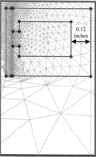
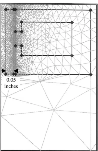
5.2.2 Modeling Metal-to-Metal Interface Tolerance... 86
5.2.3 Modeling Part Alignment Tolerance... 88
5.2.4 Modeling Shim Gap Tolerance...90
5.2.5 Sensitivity of the Model to Geometric Tolerances...91
5.2.6 Value of Modeling to Future Work...92
5.3 Stray Field A ssessm ent... 93
5.4 Valve Inductance Measurements... 94
5.4.1 Description of Experimental Technique... 94
5.4.2 Inductance Measurement Experimental Procedure...96
Chapter 6 - System Integration and Cold End Design... 97
6.1 The High Pressure Assembly...99
6.1.] Welding The High-Pressure Assembly...101
6.1.2 Cold End Flanges and Fittings...102
6.2 The Cold End Housing...105
6.2.1 Expander Space Dead Volume Minimization... 109
6.3 T he V alve A ssem bly...110
6.3.1 Valve Seat Swaging Process... 113
6.4 Fabricating Indium Seals... 115
Chapter 7 - Valve Dynamic Operation...118
7.1 Valve Disk Dynamics and Operational Time Scales... 118
7.2 Valve Seat Sealing Effectiveness...122
7.2.1 Valve Bulkhead Deflection Analysis... 124
7.2.2 Valve Seat Deflection and Sealing Analysis... 127
7.3 V alve Seat L ifetim e... 132
7.4 Control, Energy Consumption, and Dissipation... 134
7.4.1 Triple-R Valve and Energy Consumption...134
Chapter 8 - Reflections and Conclusions... 136
8.1 Technologies This Work May Enable... 138
8 .2 C o nclu sion ... 138
References...140
Appendix A - Paramagnetic Material Properties... 141
Appendix B - Static Force Data... 143
Appendix C - Valve Model Performance Data... 152
Appendix D - Valve Disk Dynamics... 161
Appendix E - Valve Bulkhead Deformation Analysis...171
1.0 INTRODUCTION
Cryogenics is the production of low temperatures and the study of low-temperature phenomena. There is a hazy temperature division line between refrigeration and
cryogenics, which occurs at about 123 Kelvin (-150' Celsius). Applications of cryogenics span from industrial processes such as gas liquefaction to studies of basic phenomena in physics and chemistry. The discipline presents a unique set of challenges encompassed
by basic property changes that occur in most substances and materials when they are
exposed to extremely low temperatures.
The work covered by this thesis focuses on the development and principal analysis of the cold end for a prototype cryogenic machine, a cryocooler, capable of demonstrating the feasibility and implementation of a miniaturized, multistage Collins cycle. This machine
is a proof-of-concept test rig used to unite several pre-existing technologies into a single device. The machine will be used to validate analytical thermodynamic results as well as to work through unanticipated challenges that may arise through the integration of various independent technologies into a single system.
The machine developed in part through this work is the precursor to a modular, three-stage cyrocooler capable of achieving Watt of cooling at 10 Kelvin. If successful, the three-stage machine will represent a two-fold increase in efficiency over existing cryocoolers capable of achieving sustained cooling at 10 Kelvin.
1.1 PROJECT MOTIVATION
The availability of a small machine capable of sustained cooling at 10 Kelvin will enable many technologies reliant upon cheap, reliable cryogenic working fluid. Current
applications include chilling military sensory equipment and enabling better resolution for astronomical observatories. However, foreseeable applications include cheap, low-temperature superconductors as well as desktop-sized supercomputers.
Many classes of small cryocoolers are currently in use today. These systems include pulse tubes, sterling machines, and Gifford-McHahon cycles. However, each of these cryocooler types is either prohibitively wasteful with respect to energy usage or is simply impractical for substantial cooling applications at 10 Kelvin.
The motivation of this project is to combine various technology advances made in the Cryogenics Engineering Laboratory at the Massachusetts Institute of Technology into a single small machine capable of executing a Collins cycle. The focus of the current effort is to develop cryogenic valve technology and the supporting cold end geometry to
1.2 COLLINS CYCLE OVERVIEW
The Collins cycle is an industrial-scale helium liquefaction process usually carried out by large machines. The Collins cycle is essentially a three-stage machine with each
intermediate stage made up of a mechanical expander and a heat exchanger. The final stage of the cycle employs a Joule-Thompson valve to expand and liquefy the helium. A schematic showing the various parts of this cycle is provided in Figure 1.1. Samuel C. Collins pioneered development of this cycle in 1946 to provide practical helium liquefaction without the need for hazardous cryogenic hydrogen as pre-coolant. Since hydrogen freezes at 13.8 Kelvin and most other substances freeze at higher temperatures, helium is the only working fluid available for applications below about 14 Kelvin.
He Compressor
Expander 1
Expander 2
J -T Valve
Figure 1.1: The Collins cycle is a
multi-stage machine consisting of counter flow heat exchangers and adiabatic expanders
Many working fluids have a positive Joule-Thompson coefficient; the fluid temperature reduces as the fluid expands at constant enthalpy - as with a throttle valve. However, cryogenic helium has a negative Joule-Thompson coefficient. Expansion at constant enthalpy causes the fluid to warm up. The only way to induce helium to cool in the 10-Kelvin regime is to take work out of it - an adiabatic expansion. Thus, a mechanical expander is necessary to execute a helium liquefaction cycle where helium is the working fluid.
As shown by the temperature-entropy diagram, Figure 1.24*, the idealized Collins cycle consists of several distinct but similar mechanical expander stages and a final Joule-Thompson expansion process. The mechanical expansion processes are identical at each stage and are repeated down the temperature scale between two isobars. These stages chill the gaseous helium below its Joule-Thompson inversion temperature. Once the inversion temperature is passed, the gas can be expanded to generate liquid helium.
Figure 1.2: The ideal Collins cycle on a T-S diagram shows the distinct mechanical stages and the final expansion to liquid
The research effort described in this thesis focuses on the development of the cold end and expander section for a single stage of the Collins cycle. Since all of the mechanical expander stages in the overall cycle will carry out similar processes, this single expander component will be used to benchmark and develop a multi-stage machine as the research evolves.
All superscripts in the text body refer to the number of the reference appearing in page 140
2
4:'
300
15 0
10
20'
4Entropy
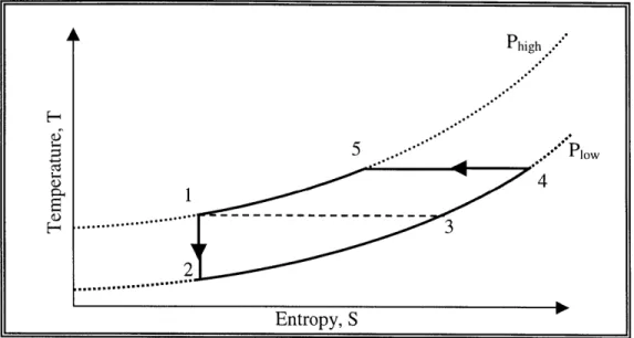
When attached to a compressor, the single-stage unit executes a set of processes akin to a reversed Brayton cycle. The setup utilized to execute this cycle is shown schematically in Figure 1.3. As shown by the temperature-entropy diagram, Figure 1.4, the cycle executed
by the one-stage unit consists of five processes: Process 1-to-2 is an adiabatic expansion
of the fluid to drop the temperature. Process 2-to-3 lifts entropy from the load at
cryogenic temperature. Process 3-to-4 is a heat exchange where the exhaust stream pre-cools the incoming working fluid. Process 4-to-5 is an isothermal compression. Process 5-to-I is a heat exchange where the incoming working fluid is cooled by the exhaust stream. Compressor
Qout
A ' Warm Reservoir LP Smart Valve (Typical) LP HPWarm Volumn PistonHeat
ExchangerGap
From Previous Stage LP Exhaust HP Cold Volume LP To Next SDage LP StreamFigure 1.3: A schematic of the single stage unit reveals its similarities to
the expanders utilized on multi-stage industrial-scale helium liquefiers
As with any cryogenic machine, it is absolutely necessary to thermally isolate the working components of the cold end to mitigate thermal leaks, which detract from the cycle's cooling power. In conventional helium liquefaction machines, thermal isolation is achieved by driving all mechanical components via cams connected to long, thin
linkages. These long linkages retard heat transfer from room temperature to the cold end and avoid mechanical friction at low temperature, but they necessitate a machine of large size. Phigh 5 Po 4 H ... ... Entropy, S
Figure 1.4: The single-stage expander unit executes a five-stage cooling process when attached to a helium compressor.
1.3 RATIONALE FOR MINIATURIZATION
The motivation for compacting an industrial-scale machine into a device a few cubic feet in volume is threefold. First, it is desirable to capture the positive attributes of the Collins
cycle in a device small enough to be dedicated to a single electronics package or capable of being plugged into a standard wall outlet. Second, a miniaturized Collins cycle would be competitive with existing small cyrocoolers used in military and astronomical
applications. Third, shrinking the system's size allows a number of technologies to be used to facilitate the cycle that would be impractical in a larger machine. These
technologies include the electromechanical valves upon which this thesis focuses.
The primary means of miniaturizing the cycle is removing the various cams and linkages
operating the valves and piston expander in favor of other driving mechanisms. In fact,
the mechanical complexities associated with conventional actuation mechanisms make
them impossible to implement as the size of the system drops. To operate the scaled-down cryocooler, alternate mechanisms must be developed.
1.4 ENABLING TECHNOLOGIES
The current effort at miniaturizing the Collins cycle is focused on the cold end and the expander, which contain all of the hardware to carry out the adiabatic expansion of the working fluid to drop its temperature, Process 1-to-2. This process is the coldest part of the cycle, and all of the mechanisms must be able to operate through a huge temperature range from room temperature down to the cooling temperature of the apparatus.
The cold end and expander can be broken down into a number of simpler parts, each of which must be modified to operate without mechanical linkages. A reciprocating floating piston expander is utilized to take energy out of the working fluid. The floating piston travels within a cylinder extracting work from the helium in the cold volume by compressing helium in a room-temperature warm volume. The motion of the floating piston is controlled by the flow of room-temperature helium into and out of the warm volume through conventional valves.
Directing the flow of working fluid through the expander at the cold end is a pair of cold valves of novel electromagnetic design. These valves are actuated by a control current generating a magnetic field that attracts the valve disk away from the valve ports. This action allows the valves to be mechanically opened and controlled very precisely by a pulse of electrical current. When the control current is not on, the cold valves act as check valves. They are held closed by the gas pressure difference across the valve ports and by a permanent magnet acting as a valve spring.
Both the cold and warm valves are controlled by a digital data acquisition and control board in a PC. The PC board monitors the warm-volume pressure and piston position. A LabView program actively controls the opening and closing of each valve so that the expansion of the helium in the cold volume approximates a reversible adiabatic process, Process 1-to-2 shown in Figure 1.4.
1.5 CONTRIBUTION OF THIS THESIS
This thesis makes several significant contributions to the field of cryogenics. The comprehensive mechanical design of a feasible cold end unit capable of executing the expander portion of one-stage of a Collins cycle is presented. Emphasis is placed upon the development of the cryogenic cold valves and their integration with the cold end. Various advantages and disadvantages of this design concept are discussed and the difficulties encountered during the development process of this new machine are catalogued.
An evolutionary design iteration process based on finite-element modeling coupled with analytical solutions is pioneered and posited. This process supplants pre-existing
cryocooler valve design methodologies by allowing the experimenter to converge on an optimal valve geometry without having to build and test hardware. When the right design is ultimately found, this thesis provides a robust, repeatable, comprehensive set of valve manufacturing processes and instructions to create a quality electromagnetic device. An experimental process for static benchmarking is described. The sensitivity of the valve to various geometric tolerances is explored and modeled, and it is demonstrated that the finite element modeling method can be utilized to reliably bound a set of experimental data. The finite element bounds are then utilized to make first-order modeling approximations for several processes of the cold end including the following: electromagnetic, mechanical, dynamic, thermodynamic, and tribological. These first-order performance calculations are instrumental in breaking down the various processes affecting the operation of the cold end. These analyses will be used as a baseline to develop more sophisticated cycle models and design rules as the cryocooler evolves from a single-stage prototype to a commercial device.
This thesis ends with a set of observations and suggested improvements for future iterations on cyrocoolers of similar design. It is hoped that outlining the pitfalls and successes encountered in this development effort will facilitate accelerated advancement towards an operable three-stage Collins cycle cryocooler.
2.0 BACKGROUND AND HARDWARE DESCRIPTION
The most significant components in the cryocooler's cold end are the two cold valves, which facilitate and check the flow of working fluid in the cold end. These valves
represent the third generation in design of electromagnetic cyrogenic valves for machines developed at the Cryogenics Engineering Laboratory at MIT. The basic configuration of both valves is the same. They each consist of a torridal valve yoke and valve disk made of solenoid-quality stainless steel. The valve disks create a seal on three Kel-F plastic valve seats that are embedded within a valve bulkhead. The valve ports are
small-diameter holes drilled through the valve bulkhead, which allow gas to pass through when the valves are opened.
2.1 PREVIOUS WORK
The pioneering work to develop electromagnetic valves for cyrogenic applications was conducted by J.A. Crunkleton2 in the 1980s. Crunkleton's work focused on modifying the original Collins cycle with a wet expander. Crunkleton was also interested in
miniaturizing the industrial-scale Collins cycle for small-scale commercial use, and his motivation for utilizing an electro-mechanical valve was to reduce size and mechanical complexity at the cold end.
In Crunkleton's original machine, the electromagnetic solenoid was placed outside of the cold end, and a long valve stem that pierced through the cold end actuated the valve disk. This configuration proved difficult to effectively seal at low temperatures, and the
mechanical complexity was not substantially reduced. Crunkleton later replaced the external solenoid with an internal low-loss solenoid as part of a cryocooler developed by
3
the Boreas company . Substantial reduction in complexity was achieved because only current carrying wires to energize the valve coil had to penetrate the cold end.
Additional significant work in utilizing electromagnetic vales for cryogenic applications was performed by K. M. Ceridon in 2001 1. The focus of this project was to modify a Gifford-McMahon cryocooler to deliver remote cooling via an addendum flow loop. Electro-mechanical valves were devised to check the oscillating pressure of the cycle to provide unidirectional flow in the external loop. Ceridon pioneered electromagnetic valve force analysis and measurement methods as well as a valve design methodology that forms the foundations of the current work. Although her valve was adequate to perform the required task, her analytical model lacked the convincing general predictive ability achieved in the current effort through finite element modeling.
The feasibility of a dry floating piston expander was demonstrated by R.E. Jones in
20007. Jones showed that a piston without any linkages driven solely by pressure
differences could be used in a controlled adiabatic expansion of gas. Jones also developed a rudimentary computer control routine to run the expander cycle without any
Ceridon's work on electromechanical valves molds naturally with Jones's work on the free piston expander and points to an integration of the two projects to develop a miniaturized cryocooler devoid of any mechanical linkages as outlined in this thesis. 2.2 VALVE HARDWARE DESCRIPTION
A majority of the hardware development work in this project has focused on the cold
valves. The cyrocooler's cold end, which is represented schematically in Figure 2.1, contains two cold valves. The inlet valve regulates flow from the high-pressure reservoir into the expander displacement volume, and the outlet valve channels expanded, cooled gas to out of the cold end the load.
Outlet Valve Yok
Inlet Valve Yoke
Outlet Valve Disk
Valve Bulkhead
-Exhaust
Inlet Valve Disk
High-Pressure Inlet
[1
Inlet Valve Coil 'Figure 2.1 This cold end schematic shows how the cold valves are positioned and
To open a valve, a command current is sent into the copper winding of the valve coil. This current sets up a magnetic field in the axial direction with respect to the valve. The field is magnified by the high-permeability steel yoke and draws the valve disk away from the valve seats, allowing working fluid to pass.
Before assembly, the valves consist of three separate parts. The valve yoke is made up a spool and a cover piece, as shown in Figure 2.5. The spool is used as a fixture upon which the copper wire of the valve coil is wound. Once the spool is completely wound, the cover piece slides over the spool to protect the valve coil and complete the magnetic circuit. The third part of the valve is the valve disk, which remains free-floating below the valve yoke when all the parts are assembled in the cold end. The valve disk is skirted
by a special non-permeable spacer ring that keeps the valve disk radially centered with
respect to the valve yoke and minimizes accidental cocking of the valve disk as it moves.
Figure 2.5 The valve yoke is made up of two pieces
The assembled inlet valve yoke is shown in a technical drawing in Figure 2.6. The constituent parts of the inlet valve, the spool, cover, and disk are shown in Figures 2.7,
2.8, and 2.9 respectively. The assembled outlet valve yoke is shown in a technical
drawing in Figure 2.10. The constituent parts of the inlet valve, the spool, cover, and disk are shown in Figures 2.11, 2.12, and 2.13 respectively.
4 0.010
fl-...
_______ / / / // / / FUSE AT ASSEMBLYSECTION AA'
Figure 2.6: The inlet valve yoke is an annular electromagnet with a small inner
diameter proving much permeable material to strengthen the magnetic field
A
i
B
... ... ... ... ... - .B
. ... ... ... ... ... ... ... ... ... ... - --- ... . ... ... ... .. ... ... ..... ... C 4?f% --...SECTION
CC
SECTION
88
Figure 2.7: The inlet valve spool is shown in quarter section to relate the detail of the eddy current groove and the wire lead holes
W IELEA OLfE
A EFDi" IN
T
D
D
.. ... ... .... ... .... ... .... .... ... ... .. . ... . ... ... .. ..... ... ... ... ... ... I ... I ... ... ... .... ... ... ... --....- ... ... ... I ... . ... ... ... ... ... ... ... ... .. ... ... ...SECTION DD
Figure 2.8: The outer diameter of the inlet valve cover is constrained by the necessity of passing small tubes past it to the hi gn reservoir
... ... ... ... . ... .. .. ..
... ... . ... ---. ....-.
.
... ... ... ... .... ... ... ... ......
//j I V /// - //Figure 2.9: The inlet valve disk checks high-pressure flow into the expander and its inner
A'-ASSEMBLY
SECTION AA'
Figure 2.10: The outlet valve yoke is constrained to a 0.96-inch inner diameter because
C
B
C..
...
.
...
..
... .. .... ...... ... ...)
ECTION
SECTION
BB
Figure 2.11: The outlet valve spool has the same valve coil area as the inlet valve,
although the outlet valve coil contains a greater length of wire because its diameter is greater
B
Dl ."EIEREk iN
VE-.R KAL. (-104VE
... .
CC
D
D
till
..
...
...
...
...
...
...
.
...
...
...
...
.
...
...
...
...
.
..
.
...
...
...
..
...
.
....
.
...
.
.
...
.
...
.
.
...
.
...
...
,'f
...
..
....
.
...
...
...
.
.
...
..
.
....
.
...
...
.
.
.
...
...
...
... . ...SECTION DD'
Figure 2.12: The outlet valve cover contains a step in its inner radius to assure proper alignment with the valve spool piece when the two are assembled
...-... I,. ... ... . . ... . ... . ... ... . . . . ...
Figure 2.13: The inner diameter of the outlet valve disk is slightly larger than 0.96 inches, assuring the expander piston does not strike it when passing through
2.3 DESCRIPTION OF DESIGN CONSTRAINTS
A number of preliminary design constraints are imposed on the geometry of the valves by
the specific requirements of minimization. The major geometric design goal is to squeeze the cyrocooler cold end into a vacuum tube two inches in diameter. This constraint assures that the expander wall presents the minimum possible cross sectional area normal to the axial direction. Reducing this area minimizes the heat leak path down the expander wall from the warm to the cold end. The extent of thermal isolation required for the cold end also sets the length of the expander housing. The piston stroke and frequency must be set accordingly to achieve the desired cyrocooler heat lift, one Watt. A one-inch piston stroke at one expansion per second was selected to achieve the proper cooling and mass flow rate of working fluid.
The valve port area from the industrial-scale helium liquefier at the Cyrogenics
Engineering Laboratory at MIT is used as a baseline to develop the required valve port area of the miniaturized cyrocooler. The large helium liquefier operates with the Collins cycle and has demonstrated satisfactory performance for over 30 years. Thus, the ratio of piston area to valve port area on the existing machine is used to determine a satisfactory valve port area for the miniature machine, which has a 0.96-inch diameter piston.
The valve port scale ratio matching the piston scale ratio yields a valve port area of about
0.0 127 square inches. This flow area must be divided evenly between the valve ports.
The individual valve ports are sized to assure minimum pressure drop through the valve ports while maintaining a geometry that can be machined. As a first estimate, this condition means keeping the working fluid velocity constant through the ports. To minimize pressure drop, the port inlet area, Ainlet, must match the port outlet area, Aoutiet. To meet this requirement, equation 2.1 is employed to solve for the necessary valve lift, L. From this analysis, the valve disk lift requirement of 0.01 is determined. Figure 2.14 graphically shows the simple valve port model used to estimate the required valve lift to assure Ainiet matched Aoutlet.
Ainiet =A) =17(dL)= Aulet (Equation 2.1)
To assure the pressure drop across the valve bulkhead remains small, the valve bulkhead design originally contained sixteen valve ports, eight for the inlet valve and eight for the outlet valve. However, three ports per valve proved to be the preferable final design because they provide three points in a true plane upon which the valve disk must seal. The size of the individual ports was not increased to accommodate the required expander mass flow because the valve lift would need to increase to accommodate the constant velocity constraint. Thus the three valve port configuration as built causes a larger pressure drop on the working fluid entering the expander section than with the eight-port design.
Second, there are practical diminishing returns in the net cross sectional area of copper in a coil of wire as the wire diameter decreases. At very small wire diameters, the wire's insulation area is as large as the cooper area. As the wire size decreases further, the current-carrying material in the valve coil volume decreases and the insulation area begins to dominate the copper area.
Third, there is a practical limit imposed by on coil manufacturability. The wire must be large enough to manually manipulate during the manufacturing process, and it must have enough durability to be wound onto the valve spool with reasonable tension without breaking. This third condition ultimately proves to be the limiting factor on wire size.
Several trial valve coil winding tests were performed with progressively smaller wire at
26-, 28-, 32-, and 34-gauge to determine where the manufacturing envelope ends. It was
found that 34-gauge wire is as small as could be reasonably handled in a manual manufacturing process. Thus 34-gauge wire became the standard wire size for cold end
valves built for this project.
2.3.1 Benefit Tradeoffs of Electromagnetic Valves
The main benefits of electromagnetic valves include eliminating the need for heat flux mitigation with long linkages, reducing the mechanical complexity in the cold end, and
facilitating an infinitely variable valve control strategy. In a system with mechanical linkages, the valve timing is set to optimize cycle performance at its operating
temperature. This hard-wired optimization for a single temperature elongates cool-down time because the cycle is not operating at peak efficiency as it cools. Electromagnetic valves can facilitate dynamic adjustments in the cycle diagram while the cryocooler is running. This feature allows the cycle to be tuned for highest efficiency during cool down as well as temperatures other than the design temperature. These features should be explored in more detail in future projects with this cryocooler as they will provide a significant advantage when the cryocooler is marketed as a commercial product.
The benefits of electromagnetic valves also bring some disadvantages. With no physical connection to the valves disks, they cannot be mechanically unstuck if they cock or jam during operation. The maximum force that can be applied is limited by the electrical tolerances of the valve yoke. In addition, all of the mechanical complexity that was removed must be replaced by electronic complexity in the cryocooler's control routine and valve actuation equipment. When considering valve lifetime, controlling the energy with which the valve disk strikes the valve seats is much more difficult through
electromagnetic actuation than it is with mechanical linkages.
Although the heat leak through mechanical linkages is eliminated, it is replaced to some extent by the heat leakage through the valve coil leads. In addition, the current driving the electromagnet is dissipated in the cold end by joule heating. This addition of heat to the cold end must be precisely controlled to assure the cold end does not begin heating the load instead of cooling it.
The electromagnetic components of the valves consist of a valve yoke, a valve disk, and an array of permanent magnets. The valves are normally closed as the permanent magnets hold the valve disk against a set of valve seats, blocking flow through the valve ports. To open the valves, a valve coil in the valve yoke is energized with current, creating a magnetic field. This field draws the valve disk away from the permanent magnets to open the valve port. To close the valves, the current through the valve coil is removed. The magnetic field generated by the valve yoke disappears, and the permanent magnets attract the valve disk to its closed position on the valve seats.
To prepare a faithful model of the actual valves, significant research had to be conducted to assure material properties, performance requirements, and numerous other parameters were well understood. Many of these parameters had to be translated in some fashion to be entered into the finite element model. It was also important to check that the finite element code returned values consistent with conventional analytical approximations.
3.1 PHYSICAL AND MATERIAL PARAMETERS
Perhaps the most important aspect of the valve's design is selection of the material used to build the valve yoke. Where electromagnetism is concerned, materials are divided up into two broad categories. Nonmagnetic materials are those unaffected by the presence of a magnetic field, and examples include plastic and brick. Paramagnetic materials, in contrast, respond to magnetic fields by generating fields of their own. This response can be thought of as an alignment of small magnetic domains in the material such that the magnetic poles of the domains point in the same direction.
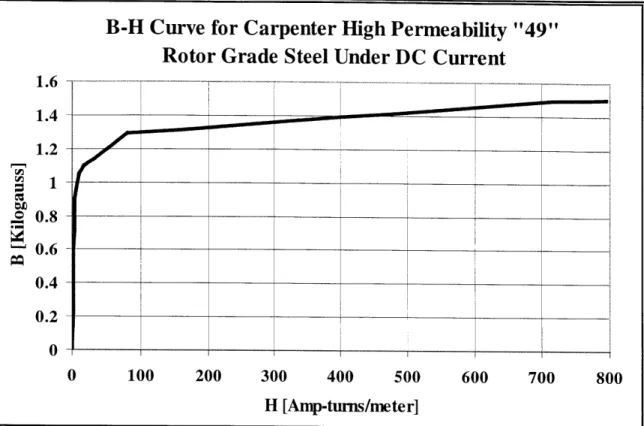
Paramagnetic materials are used in engineering applications to amplify the strength of magnetic fields generated by the electric current carried through wires. In these applications, the magnetic flux lines link the wire coil and the material amplifying the magnetic field. This combination of paramagnetic material with coils of current carrying wire is called an electromagnet. When designing an electromagnetic, some choices of paramagnetic material are better than others. The magnitude of a material's ability to enhance magnetic fields is contained in a plot of magnetic flux density in the material, H, verses the resulting magnetic field density, B. This plot is commonly referred to as a B-H curve, and an example B-H curve is presented in Figure 3.2.
Valve Disk Valve
Lift A0ut -+
T
Valve Porti Valve Bulkhead
For AP=O, Ai, = Aou
Ain
Figure 2.14: Equilibrating the areas of the valve ports determines valve lift
The maximum pressure differential in the cycle, 250 pounds-per-square-inch, creates several mechanical and electrical design requirements. The valves must open against 250 pounds-per-square inch multiplied by the total cross sectional area of the valve ports. The valves are designed to overcome the force induced on the valve disk by the pressure difference across eight 0.045-inch diameter valve ports. Each valve yoke is built to generate at least 14.2 newtons of opening force on the valve disk when in its closed position. This level of performance is used as the benchmark design value throughout this thesis, and it yields the requirement that 110 amp-turns is the opening current used in valve static finite element modeling. Regardless, it is important to note that after the valves were built, the valve bulkhead design was modified to reduce the number of valve ports, from eight to three. Thus, the valves need only open against 5.55 newtons of force, and as a result, they are severely over designed in the current application.
Two components make up the value of amp-turns that can be applied to the valve coil: 1) the number of wire turns wound on the valve coil and 2) the number of amps driven through the valve coil circuit. It is important to minimize the number of input amps to keep joule heating in check. Thus, maximizing the number of wire turns in the valve coil is desirable. Since the space set aside for the valve coil in the valve yoke is limited, it is attractive the select the smallest possible wire gauge size to maximize the number of wire turns. However, there are three practical limits preventing unlimited reduction of wire size.
First, a coil wound with small gauge wire has many more windings than a coil of larger wire wound into the same volume. Thus, the coil of smaller wire has a higher resistance, and more voltage is required to push current through it. There is a voltage at which current jumps through the wire's insulation and short-circuits the coil. This voltage is the maximum that can be safely imposed upon the leads of a coil. For small-gauge wire the practical voltage limit occurs at about 100 volts.
Figure 3.2 This B-H curve represents the electromagnetic properties
good paramagnetic material, HP49, which is used to make the solenoid
and behavior of a cores.
B-H curves have two important properties that can be used to determine which materiel is preferred when creating an electromagnet. The first property is magnetic permeability, g, which is represented by the slope of the line on the B-H curve. This property dictates the extent of magnetic field density generated in a material for a particular input magnetic flield intensity and can be found from Equation 3.1. Physically, permeability can be thought of as the extent to which the poles of magnetic domains in the material align for a given input magnetic field intensity.
p(H) = dB(H) Equation (3.1) dH
Once all of the domains align to the greatest extent possible, addition of magnetic field intensity does not induce any greater magnetic field in the material. This property is called the magnetic saturation density, Bsat, and it is the second important feature of a B-H curve. This property is manifested when the slope of the B-B-H curve dramatically changes from steep to very shallow, and the value of B increases only slightly even when the input H increases substantially. Saturation density is important to material selection in electromagnets because it dictates the maximum flux enhancement that can be derived from a particular paramagnetic material.
B-H Curve for Carpenter High Permeability "49"
Rotor Grade Steel Under DC Current
1.6 -- - - - --- - ---- -1.4 1.2 0.8 0.4 0.2-0 0 100 200 300 400 500 600 700 800 H [Amp-turns/meter]
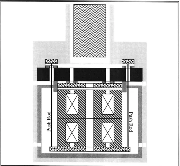
Another disadvantage of the current design is that the outlet valve resides in the expander space. A substantial amount of dead volume arises form the thin space surrounding the valve, which detracts from the cryocooler's performance. Although great measures were taken to reduce the extent of this dead volume, the design geometry makes it
unavoidable.
One possible solution to this problem is to put both valve coils in the high-pressure space and actuate one of the valve disks through the valve bulkhead using push rods, as shown in Figure 2.15. While eliminating dead volume, this concept will have some severe sealing, and size restriction issues that must be overcome if it is to be practically implemented in future designs.
1.
Ji
Figure 2.15: Although awkward, removing the valve from the expander space and
3.0 VALVE GEOMETRY OPTIMIZATION
Previous cold valve designs have been hindered by lack of an adequate performance prediction technique. Classical magnetic modeling methods such as the one-dimensional circuit approximation are idealizations that break down because geometric
considerations, material properties, and flux leakage become complex or uncertain. Using only these rudimentary models, uncertainties in performance are large and gross over design is necessary to assure adequate performance.
An alternative approach explored in this thesis is the use of a magnitostatic finite element modeling code to explore valve performance before any hardware is built. The code of choice to perform this analysis is Quickfield 4.3 by Tera Analysis. The drivers for selecting this code over other packages include its reasonable cost, $950 per year academic license, and its relative ease of use. The code is not as sophisticated as other packages because it does not allow true three-dimensional modeling. However, symmetric systems can be modeled. Although the cold valves are not perfectly axi-symmetric, results produced by Quickfield provide a performance approximation of far greater accuracy than any simple analytical method.
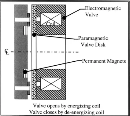
In the axi-symmetric mode, Quickfield's user interface only allows the user to draw model cross sections with the centerline running horizontally. This restraint causes the model to be rotated 90 degrees so that it lays vertically instead of horizontally, which is how the machine sits in actual operation. Figure 3.1 denotes the important magnetic components of the valve design whose Quickfield models are described throughout this thesis. Figure 3.1 shows the components in the orientation used to model them.
Electromagnetic Valve
Paramagnetic Valve Disk
Permanent Magnets
Valve opens by energizing coil Valve closes by de-energizing coil
Figure 3.1 The components created via finite element are
3.1.1 B-H Curves, Machine-ability, and Material Selection
The ideal material for an electromagnet yoke has high permeability and a high magnetic saturation density. It also must be a soft magnetic material with low hysteretic loss associated with changing the magnetic field. Such a material would create a powerful magnetic field for little input magnetic flux density and the magnetic field density would continue to increase rapidly even for very high valves of H. In addition, when H is removed, the magnetic field density would also go to zero instead of lingering at some non-zero value. This point is significant because the magnetic field produced by the valve yoke must return to zero if the valve is to close properly when the current in
de-energized.
Since electromagnetic coil windings are prevalent in modern machines, many candidate materials have been developed that provide a good union of desirable magnetic and mechanical properties. In general, these materials are referred to as solenoid-quality steel. The Carpenter company produces several such metals, and two specific types were explored for this valve application: HP49 and 430FR. Although HP49 has the superior magnetic properties, it has higher tensile strength than 430FR, making it more difficult to machine. In addition, 430FR has a higher electrical resistance, which makes it better at managing eddy currents and the associated losses that arise in the material when transient conditions exist. Thus, 430FR was selected as the material of choice for the valve yoke.
A sample B-H curve for 430FR is presented in Figure 3.3 and technical data on this
material from the manufacturer is presented in Appendix A.
B-H Curve for Carpenter 430FR Solenoid-Quality
Steel at less than 0.375-inch Radius
1.4 -1.2 I t 0 1000 2000 3000 4000 5000 6000 7000 8000 H [Amp-turns/meter]
Figure 3.3 This B-H curve is for 430FR, a commercially available ring coil-quality steel
hat can be annealed after machining to restore lost paramagnetic properties.
1 0.8 0.6 0.4 0.2 0 I ________ - I *1 - ___ ___ ___ ___ 1 1 r 1 r
3.1.2 Modeling the B-H Curve
With the valve yoke material selected, its magnetic properties can be entered into the Quickfield finite element code to begin building up the model. The program has a user interface allowing points from the material's B-H curve to be entered. The software then references this data as it creates the field solution.
Several methods of modeling the B-H curve were considered. The classical method used to deal with these curves is to represent the major portions of the plot with two
intersecting straight lines as shown in Figure 3.4. This method characterizes a majority of the data very well. However, the transition region to magnetic saturation is not well captured. Thus, this modeling method was discarded because it is anticipated that with good design, the valve yoke would skirt the material saturation envelope.
B-H Curve for Carpenter 430FR Solenoid-Quality
Steel at less than 0.375-inch Radius
1 .4 -
-
--~1 II I I I i1 18 0
0 1000 2000 3000 4000 5000 6000 7000 8000
H [Amp-turns/meter]
Figure 3.4 The B-H curve can be well represented by two straight lines, but the details of
the transition to saturation region are not captured by this approach
Another modeling method that can be employed is to pick as many points as possible
from the manufacturer's B-H curve and enter these points into the finite element code user interface. This method is problematic because B-H curves usually appear in manufacturer literature on semi-logarithm plots and the potential for error in picking
points is substantial. In addition, Quickfield is highly sensitive to nonphysical features in
user-defined B-H curves, and the program will not solve most problems unless the B-H curve is a completely smooth array of points. User-defined curves with many points were
found to be relatively unphysical and caused Quickfield to fail. 1 0.8 0.6 0.4 0.2 a r r * i
F
F
0r
*1 ____________ ____________ ____________The ideal B-H curve modeling method for finite element codes is a combination of the two-line approximation with the point-picking method. Seven to eight total points are used to define the B-H curve. The plot is principally made up of two long straight lines
with the transition between the lines defined by a detailed set of points. This approach provides a simple but accurate material B-H curve for the finite element code to utilize. It turns out that the valve's performance is relatively insensitive to the material's
magnetic saturation density because the valve is over designed. Under normal operation, most of the paramagnetic material in the yoke does not saturate, and Section 5.2.1 discusses this finding in more detail. The permeability of the material's B-H curve, however, is important. Once the valve yoke parts are machined, they are annealed to restore the metal's paramagnetic properties. This annealing process, covered in Section
4.1, assures that the material's actual B-H curve is similar to the manufactures curve used
to create the finite element model.
3.2 TRANSLATING OPERATIONAL REQUIREMENTS
In Chapter 2, all of the valve design requirements are outlined as they relate to the
physical constraints on the miniaturized cyrocooler. Once these requirements are defined, they can be translated into the finite element model. Quickfield employs a graphic user interface that allows the programmer to draw in two dimensions a characteristic cross section of the axi-symmetric solid of revolution that makes up the model. All geometric features of the valve are entered into the finite element code by drawing them.
The valve opening force requirement based on the maximum cycle pressure differential is outlined in Chapter 2. The finite element code's post processing analyzer allows the user to determine the force generated on various pieces of the geometry in the model. In the model, as in the real valve, the force on the valve disk increases as the valve coil is
energized to higher amp-turn values. Thus, an amp-turn value must be set as a benchmark to determine whether adequate force is being generated on the valve disk, and the
following methodology was utilized.
Initial valve coil winding tests with 28-gauge wire demonstrate that about 250 turns can be placed on the prototype valve ring coil. These coils have an average resistance of about 6.25 ohms. The design calls for the cyrcooler to lift one Watt of heat at 10 Kelvin. The cyrocooler can lift more heat at higher temperature, and the valve coil resistance will drop with operating temperature. Regardless, it is assured that the valves will never dissipate more power than the cooler can lift if the maximum valve coil power is set to one Watt. One watt through a resistance of 6.25 ohms results in a maximum current of 0.4 amps, and 0.4 amps multiplied by 250 winding turns yields 100 amps-turns. Thus, this value is selected as the benchmark input for the finite element model. Quickfield allows the user to define any solid geometric component as an electrical coil and the amp-turns through that coil can be set to any value. The value of 100 amp-turns is utilized in all finite element benchmarking model tests to determine the optimum valve geometry.
The evolutionary approach proceeds so that the range for each type of improvement is exercised individually. To determine the order of exploration, the experimenter must make educated engineering judgments about which factors will most influence the valve's performance. In general, the most favorable value for the characteristic being explored is incorporated into the geometry and carried into the next iteration. In this way, the valve design evolves from the baseline model to the final geometry.
It is important to note that this development process may not have captured the best possible combination of properties in the design space because not all combinations of characteristics were examined. The selection of the order in which the characteristics were explored may have a substantial influence on the final outcome. In some cases, it is not clear which characteristics have the most influence on performance and the selection of which to explore first is somewhat arbitrary. Regardless, this process provides a substantial improvement over previous design methods based on simple analytical models. It allows the designer to exercise and explore the affects of many geometry changes that might be too small to model accurately model with a less sophisticated method.
3.3.1 Outlet Valve Iterative Design Process
The following section covers each of the geometric improvements made to the baseline model in the order they were explored. It explains the trends gleaned from changing characteristic values of each property and why a particular geometry was selected over another one. Following the figures showing the valve configuration with each
evolutionary improvement, a depiction of the evolution of the valve from the baseline to the final design can be realized.
The baseline model is characterized by a cross-sectional area square in shape. When swept around 360 degrees, this shape generates an annular volume of rotation with an outer diameter of 1.8 inches and an inner diameter of 0.96 inches. The wall thickness of the valve yoke and valve disk is 0.03 inches on all sides. The cross sectional area of the valve coil has a 1:1 width to length aspect ratio, and there is no rounding or filleting of the valve coil corners. In the closed position, the valve disk sits 0.01 inches away from the valve yoke. The valve disk force produced by this design is 3.6837 newtons.
1) Valve Yoke Outer Diameter
Increasing the outer diameter of the yoke was found to increase the force generated on the valve disk. Analytically this result follows because increased outer diameter yields an increased surface area normal to the magnetic flux lines. More area for the flux to travel through translates into a drop in the equivalent flux resistance of the valve yoke in the one-dimensional circuit model. Unfortunately, the valve's outer diameter is limited by the 2-inch constraint imposed in the design specifications. Although the outer diameter was made as large as possible, it was reduced to 1.78 inches to accommodate the thickness of the cold end wall housing.
Valve Force Variation with Valve Coil Aspect Ratio
4 3.8 63.6 3.4 3.2 3 2.8 1 1 1 3 5 7 9 11 13Valve Coil Aspect Ratio
Figure 3.8 The optimal coil ratio is difficult to pinpoint because the data is severely
scattered; a fourth-order polynomial fit was used in an attempt to find the maximum
In general, it is expected that valve force will increase with aspect ratio because a greater
volume of copper conductor is placed in the valve yoke as the aspect ratio goes up. As described above, the benefits of this affect disappear when the valve coil becomes thin
because magnetic flux jumps across the coil instead of traveling around the valve yoke. According to a fourth-order polynomial fit to the severely fluctuating data, the analysis indicates that a valve coil aspect ratio of about 4 provides the best performance.
However, the data is highly scattered owing to second-order affects, and the actual band
of possible optimal coil aspect ratios lies between about 1.5 and 6.5.
When the aspect ratio study was originally conducted, the aspect ratio was truly isolated from all other factors by holding the outer diameter of the valves constant and fixing the volume of copper wire. Holding the copper volume constant instead of cross sectional area yielded the conclusion that aspect ratio alone has little affect on valve performance. Instead, it is the additional volume of copper in the valve coil winding engendered by higher aspect ratio that provides the true enhancement of valve performance.
Unfortunately, this analysis was conducted early in the development stage of the valve
and the experimenter did not realize the supplemental benefit of adding additional copper volume when exploring the coil aspect ratio. Since aspect ratio alone has no effect, the valve remained unchanged from the geometry presented in Figure 3.6 after the aspect ratio analysis. It is suggested that future cold valve development projects explore the
performance benefits afforded by additional conductor volume for valve coils with aspect
3.3 DESIGN BY EVOLUTIONARY ITERATION
The majority of the valve development work took place on the computer by exercising the finite element model through various geometric iterations to converge on the final design. A simple baseline model was selected and used to benchmark all iterations. This model, shown in Figure 3.5 meets the basic geometric design constraints but does not
meet the opening force requirements outlined in Chapter 2. Note that all finite element models presented in this thesis are characteristic cross sections representing a volume of rotation. The boundaries of each model have been greatly truncated to allow the figures to fit on the page. The actual model boundary in all cases as a square eight inches on each side that allows no flux to pass through it.
A matrix of possible geometric improvements was developed to dictate how the baseline
model could be enhanced to provide better performance. Early on, it was realized that the number of parameters requiring exploration was large and the range of characteristic values for each parameter was even larger. Checking every possible combination of geometric improvements for the optimal combination would have taken much more time than was available to complete the development effort. Thus, the exhaustive approach was abandoned and an evolutionary iteration process that could be completed in the appropriate timescale was adopted.
Physical Features Movable Valve Disk Valve Coil-" Air Gap-Valve Yoke-/ Center Line--,
Finite Element Features
Corners denoted by large diamond dots
-Solid lines represent solid surfaces
Gray lines are finite element mesh
According to Quickfield, the inlet valve design is capable of generating 25.003 newtons of force with an input current of 100 amps-turns. This performance represents an increase of about 7.35 times over the inlet valve baseline model and an opening force 189 percent in excess of the required value. The inlet valve model will require much less than 100 amps-turns of input current to meet the design force requirements.
3.4 PERMANENT MAGNETS AS VALVE SPRINGS
Opening the valve ports is accomplished by energizing the valve coil, which magnetically attracts the valve disk away from the valve ports toward the valve yoke. However, a method is required to assure the valve disk returns to the closed position when the valve coil is de-energized. Gravity is ruled out as a primary restoring force because the
cyrocooler may ultimately see service in satellites where it will have to function in the absence of gravity. In addition the vertical orientation of the valves causes gravity to act against the closing direction of the inlet valve. The pressure differential across the valve ports is employed to seal the valve disk to the valve ports. However, if there is no sealing force on the valve disk when the pressure difference across the valve ports is zero, back pressure cannot build up to engender further sealing.
Many conventional electromagnetic valves utilize a spring or flexure to return the valve disk to its normally closed position. Ceridoni utilized a spiral flexure to generate the restoring force and maintain lateral stability against unstable magnetic forces in her cyogenic valve. The current design enjoys natural lateral stability of magnetic forces. To reduce mechanical complexity, the valve disks are not physically connected to anything and are free floating in the magnetic field.
An array of small permanent magnets acts as a magnetic valve spring. An arbitrary force of 2 newtons on the valve disk was selected as the target for incorporating permanent magnets into the design. The selection of this performance metric is not without thought, however. During normal cryoccoler operation the permanent magnets impose a force on the valve disk in addition to the force generated by the pressure differential across the valve ports. This added force is a supplemental burden against which the valve ring coil will have to act to open the valve ports. Thus, the force generated on the valve disk by the permanent magnets has to be as small as possible while providing adequate force to close the valve and seal the valve ports in the absence of backpressure.
3.4.1 Magnet Material Selection
Two types of hard magnetic material were considered to make the magnetic valve springs: SmCol 8 and NdFeB. The materials are attractive candidates because they both can carry strong permanent magnetic fields, they are commercially available, and they come in very small sizes.
2) Valve Yoke Inner Diameter
Decreasing the inner annular diameter increases the amount of paramagnetic material for the magnetic flux to travel through and thus increases the valve's induced force. The outlet valve's inner diameter is constrained to be no smaller than 0.96 inches because the expander piston, which has an outer diameter just less than 0.96 inches, must travel through the outlet valve's inner hole. The inlet valve, which was developed after the outlet valve geometry was fixed, has no practical limit on the minimum size of the inner diameter. An inner diameter of 0.42 inches was selected because the finite element model exhibited diminishing returns on performance for further decreases in inner diameter. Figure 3.6 demonstrates how the valve cross-section appears after both inner and outer diameters are selected. This design keeps the wall thickness of the yoke and valve disk at
0.03 inches, but the decrease in outer diameter modifies the cross sectional area of the
coil to an aspect ratio of 1.06. The force produced by this design is 3.7175 newtons. Despite the reduced outer diameter, this increase in force is due to the change in valve coil aspect ratio, which will be examined next.
Outer Dia. Inner Dia.
Figure 3.6 The valve model evolves