Publisher’s version / Version de l'éditeur:
Vous avez des questions? Nous pouvons vous aider. Pour communiquer directement avec un auteur, consultez la première page de la revue dans laquelle son article a été publié afin de trouver ses coordonnées. Si vous n’arrivez pas à les repérer, communiquez avec nous à [email protected].
Questions? Contact the NRC Publications Archive team at
[email protected]. If you wish to email the authors directly, please see the first page of the publication for their contact information.
https://publications-cnrc.canada.ca/fra/droits
L’accès à ce site Web et l’utilisation de son contenu sont assujettis aux conditions présentées dans le site LISEZ CES CONDITIONS ATTENTIVEMENT AVANT D’UTILISER CE SITE WEB.
Internal Report (National Research Council of Canada. Division of Building
Research), 1968-09-01
READ THESE TERMS AND CONDITIONS CAREFULLY BEFORE USING THIS WEBSITE.
https://nrc-publications.canada.ca/eng/copyright
NRC Publications Archive Record / Notice des Archives des publications du CNRC :
https://nrc-publications.canada.ca/eng/view/object/?id=000ef9bc-2dc3-48bb-b5e6-267e25f6e131 https://publications-cnrc.canada.ca/fra/voir/objet/?id=000ef9bc-2dc3-48bb-b5e6-267e25f6e131
For the publisher’s version, please access the DOI link below./ Pour consulter la version de l’éditeur, utilisez le lien DOI ci-dessous.
https://doi.org/10.4224/20338301
Access and use of this website and the material on it are subject to the Terms and Conditions set forth at
Direct simple shear tests on Leda clay
DIRECT SIMPLE SHEAR TESTS ON LEDA CLAY
by
K.N. Burn
ANAL VZeD
Internal Report No. 363 of the
Division of Building Research
OTTAWA September 1968
by
K.N. Burn
The direct simple shear device was developed over a period of 5 or 6 years at the Norwegian Geotechnical Institute. The
model used in these tests is described fully in a paper by Bjerrum and Landva in Ge ote chnique , March 1966. Its construction was inspired by a large field shear box. the re sul.t s from which agreed much more closely with field performance than the values obtained from triaxial tests. The apparatus works extremely well on soft Norwegian quick clays but a problem of sliding at bearing surfaces arose in an attempt to use it on a sample of stiff Leda clay from Hiawatha Park near Ottawa. It was with the hope of solving this problem that the writer went to Norway and conducted the following experiments on samples of Leda clay, the strength properties of which in terms of "peak" and "residual" strengths had been previously determined with triaxial and direct shear tests. SAMPLE PREPARATION
A device machined to very close tolerances is used to trim and place the bearing plates and reinforced membrane around the soil sample. It is normally mounted in an inverted position above the sample extruder and receives the soil sample which is jacked into it. Rough trimming of the sample is done during jacking to prevent the cutting ring from being fouled. but the fine trimming is effected by the cutting edge on the sampler ring. A rough horizontal cut is made below the sample with a wire and a thin stainless steel plate to
separate the test specimen from the sampler tube.
The trimming device is then carefully taken from the mounting bracket. inverted. and the upper and lower surfaces trimmed to receive the bearing plates and filter stones. Following this. the cutting ring is removed and replaced by a reinforced membrane. The sample is then ready to be mounted on the shearing device.
Leda clay samples, being much stiffer than Norwegian clay, were not suitable for this type of t r i.rnrrririg and it was necessary to rn odify the procedure for preparing the s arnpl.e s , The basic difference was the need to shave the edges of the sarnple to within
t
ITlITl of the cutting edge with a sharp knife and then to advance the cutting ring 2 to 3 ITlITl at a tirne , This is the s arn e sort of oper-ation as that used in the preparoper-ation of consolidoper-ation s ampl.e s at Ottawa, but c onaurnes rnu ch rno r e t irrie than is necessary inpreparing the Norwegian quick clays. It also takes longer to tr irn the horizontal surfaces since this cannot be done s lrnpl.y by using a wire saw and one or two deft strokes with a straight-edge. The finished spe c irnen is 50 CITl2 in area (approximately 8 CITl in
diarne te r) and 1. 45 CITl high. CONSOLIDATION
The s arnpl e is transferred to the shearing apparatus by attaching the tr-irnrnirig device to the front of the shearing
apparatus and sliding the rnourrting pedestal into place beneath the loading fr arrie where it is firITlly attached to the base plate
(Figure 1). The lever a r m syst ern is then lowered until the loading plate is in contact with the upper bearing plate. Weights as
required are added to the lever a r rn in the s arrie fashion as in the cons ol'idornete r test and vertical di spl.ace ment s with ttrne are
recorded. When consolidation under the desired rior rna.I stress has been cornpl.eted , the s arnpl.e is ready for shearing.
SHEARING
The loading plate is locked to the upper bearing plate by adjusting two horizontal stops. Pins in the loading plate are pulled to allow it to move freely in a horizontal direction and the s arnpl,e is then sheared by applying a horizontal force (Figure 2).
For undrained constant volurne tests, the vertical load is adjusted by attaching the loading a.r rn to an anchor which can be rnove d vertically by a gear control (Figure l }, If the s arrrpl e tends to expand or dilate while undergoing shear the nor ma.l load mu st be increased to prevent it fr orn doing so, thus avoiding the setting up of negative pore-water pressures. If, on the other hand, the sarnple tends to c ornp r e s s , the vertical load mu st be reduced to prevent positive pore-water pressures fr orn being generated.
A dial gauge m.ounted above the loading plate indicates the vertical m.ovem.ents that occur between it and the base plate (Figure 1). Control of the volum.e of the specim.en, however, does not simply lie in altering the vertical load to m.aintain a fixed reading on the dial gauge but rnu st perm.it those vertical displacements to take place that are concomitant with the com.-pre s sibility of the loading plate.
Drained tests are perform.ed at an appropriate rate of strain and the sam.ple is perm.itted to change volum.e under a constant vertical load. In view of the tim.e allowed for this study it was not practicable to conduct any drained tests which take a week or m.ore to run. The faster undrained tests suited the purpose better since the problem was m.ainly one of observing whether or not shearing stresses were being transferred from. the apparatus to the upper and lower surfaces of the sam.ple without sliding taking place between the bearing plates and the sarnple ,
The normal stresses applied to the sam.ples were kept within the range generally encountered in natural slope stability problem.s, i. e. up to 1.0 kg/ cm. 2• Except in the case of one specim.en of clay from Gloucester, consolidation was unnecessary since the pre-consolidation stresses for tb e other two sam.ples are considerably in excess of 1.0 kg/ cm. 2• Higher norm.al stresses than those at which the specim.ens were sheared were applied tem.porarily to m.ost sam.ples only in order .:0 assure good contact between loading
plates and the upper and lower surfaces of the spe cirnen.s ,
Approxim.ately 2 per cent compression between the base and loading plates, which m.ay be largely seating adju strnerit s , was m.easured in most tests.
SHEAR TEST RESULTS
The tests are described in sequence with com.mentary on the efficacy of each and the steps taken at certain stages to im.prove it. The rnaxirnum strengths were com.pared to those obtained in tests conducted in the direct shear box on sam.ple 94-26 (Figure 3). It was not expected that the values obtained from. sets of tests would be identical since the distribution of stresses imposed on the specim.ens would not be the s arrie and the m.odes of failure would differ in consequence. All tests recorded here were conducted with rates of strain of 1 rnrn in 2 hours.
SOILS
Leda clay samples that were tested came from three sites. 1. A very soft, normally consolidated material from C. F. S.
Gloucester Naval Station - sample No. 124-24-4. Depth: 14 ft 6 in. to 15 ft 0 in. p = 0.6 kg/cm 2
c
2. A stiff, highly overconsolidated material from the Ottawa Sewage Treatment Plant - sample No. 94-26. Depth: 62 ft 6 in. p
=
4.5 kg/ cm 2c
3. A medium stiff, moderately overconsolidated material from the Montreal Road laboratory site - sample No. 20. Depth: 31 ft 3 in. to 31 ft 9 in. p = 1 • 9 kg/ c m 2.
c
The sample from the sewage treatment plant was a block taken from the excavation for the main building in 1962. The other two were 5-in. diameter Osterberg samples obtained in 1965. The testing programme was concentrated on the stiffest samples. Test No.1 - Specimen 94-26A
Three blades 2 mm high and 0.2 mm thick had been installed in the bronze filters of two of the bearing plates. One was mounted across the centre and the other two parallel to it on either side, spaced at 20 rnrn, They were mounted as spacers between sections of sintered bronze and sealed in place with an epoxy resin (Figure 4).
The specimen was trimmed and the bearing plates attached top and bottom by applying a hand pre s sure to sink the blade s into the soil. Care was taken when placing the specimens in the apparatus to be sure that the blades were oriented transversely to the direction of thrust. A normal stress t?f 0.25 kg/ cm 2 was applied and the specimen sheared. The maximum developed shearing strength at a reduced normal load was considerably lower than expected.
Much of the measured strain had very obviously not been applied to the specimen. After removal of the specimen from the apparatus the soil surfaces were examined and it was found that the specimen and filter stones had actually touched over only about
5 per cent of their contact a re a s and that some noticeable disturbance had been caused when the blades were pushed into the clay. Shearing had occurred locally, leaving a space behind each blade which
It was obvious that a higher seating load was necessary in order to obtain better contact. To reduce disturbance caused by pushing the blades into the surface of the specimen, they were filed down to
It
rnrn high and the edges sharpened.Test No. 2 - Specimen 94-26B
This test was run beginning at the same normal stress of 0.25 kg/ cm 2 after a seating load of 2.00 kg/ cm 2 had been imposed. During the te st the sample appeared to dilate and the normal stre s s was increased to a maximum of 0.58 kg/ cm 2 (Figure 3). The maximum Twas O. 5 kg/ cm2 but there was obvious displacement between the loading plates arid the specimen. When the specimen was examined following the test it was found that the surfaces of the clay had again been disturbed when the blades were pushed into them and that failure had developed in the same manner as in the previous test. Local failure at the blades was again evident, and much of the applied strain could be accounted for by the width of the spaces behind the blades and by the length of the scratch marks in the drag pattern made by the bronze filters.
Contact between the specimen and filters had been improved but there was still an area of about 40 per cent of the total where the clay had not been marked by the filters. Upon closer exam-ination it was discovered that the separate sections of porous
stone between the blade s had not been replaced with their surface s in the same plane. Some ends were higher than the rim of the bearing plate, and others were lower, so that it was not possible except with a very soft material to obtain lOO per cent contact over the surface of the sample.
Test No.3
One more attempt was made using this technique but this time a softer sample (124-24-4C) was used. The blades were easily pushed into the surface of the sample. A seating load of only
0.4 kg/ cm 2 was used 「・」。オウセ the preconsolidation IZressure of this material is so low, and a normal load of 0.2 kg/ ern was applied at the beginning of shearing. The profile of the specimen and bearing plates again indicated sliding at the surfaces at an early stage in the test so the shearing stress was released and the normal stress increased to 0.4
kg!
cm 2• Shearing stresses were again applied andsome small increase in T was noticed, but sliding at the surfaces
was again obvious. As in the cases of the two previous tests, local failure at the blades had occurred, but some shearing planes in one zone of the sample indicated that plane strain conditions had been imposed to a limited extent (Figures 5b and 7). Some dis-turbance at the blades was evident as in the previous tests and
although surface contact was much improved, it was still not complete. At this stage it was realized that improved filters were needed and new ones made of ceramic material to facilitate moulding were ordered. These were to have five parallel grooves 2 mm by 2mm spaced at about 15 mm, into which stainless steel razor edges could be installed. Casting the grooves would ensure that the surface of the filter would be in contact with the surface of the specimen and the sharp thin blades would cause little disturbance when pushed into the soil.
In the meantime, two other tests were conducted in which the effects of the disturbance were reduced by setting the thicker blades in grooves filled with plaster of Paris to form keys. A tool was
made in the form of a chisel with a cutting edge 2 mm wide (Figure 6). To ensure a constant depth for the grooves a shoulder stop was made 2 mm plus the thickness of the straight edge from the cutting edge. The grooves were made 2 mm wide by 2 mm deep to allow for slight misalignment and errors in positioning the blades (the blades were not all straight; some curved as much as 1 mm from one side to the other) and to be sure that the plaster of Paris keys were continuous beneath the bottom edges of the copper blades of the bearing plates. The grooves were cut carefully and cleanly in the positions marked by the edges of the blades on the surface of the sample. They were filled with liquid plaster of Paris and allowed to set after the bearing plate had been lowered into position. Both surfaces were treated in this manner.
Tests Nos. 4 and 5
Tests were then conducted on samples 94-26C and E using seating loads of 3.5 kg/cm2and 2.0 kg/cm 2 respectively, both with an initialnormalstressof 0
=
O.75kg/cm2•n
Sample E was tested first and a considerable increase in shear strength was obtained. It was necessary when T had reached about 0.4 kg/ cm2 to increase the normal stress since the specimen
appeared to be dilating. an clirn.bed to about 1.0 kg/ ern2 and 1"
continued to increase even when a was again reduced. Maxirn.urn. stres ses approached those values セ「エ。ゥョ・、 using the direct shear box (Figure 3).
It was unnecessary at first to vary the norrn.a1 stress on specirn.en 94-26C, which was subjected to a higher seating load
since it appeared neither to dilate nor to compr e e s , When T reached
about 0.5 kg/ ern. 2 however, it exhibited a tendency to shrink and the norrn.al stress was reduced. After about I rn.rn. of strain had been irn.posed, and s o me sliding had obviously occurred, the shearing stress was released and was reapplied while the norrn.al stress was rn.aintained at 0.74 kg/ crn. 2• A peak shear strength of 0.55 kg/ crn.2 was reached before sliding again occurred.
Both specirn.ens, when exarn.ined after the tests (Figure 8), exhibited shearing planes in the sarn.e locations as in all the previous tests, the only difference being that the shearing planes were longer! probably in proportion to the rn.axirn.urn. shearing stress obtained. No attern.pt was rn.ade to rn.easure their length.
Preparation of these two specirn.ens differed only in one aspect. For the first, 94-26E, an attern.pt was rn.ade to put just the right arn.ount of plaster of Paris in the grooves, but a srn.all excess
resulted. When the bearing plates were pushed down on the surfaces of the specirn.en, this excess spread between the specirn.en and filter plate (Figure 5) thus producing a thin void between the m , As visible in Figure 8, contact between specirn.en and filter was still not c orripl.ete , Local failure occurred at the plaster of Paris keys as it did before and the resultant upward force produced a dilation effect. When the second
sarn.ple was prepared the slight exce s s of plaster of Paris was rern.oved by a straight-edge when still liquid and none appeared afterward to have flowed between spe c lrnen and filters. This, together with the
higher seating load of 3.5 kg/ ern. 2 , gave better contact and the specirn.en failed without any indication of dilation.
Test 6
One other test was conducted on a soft s arnpl e , 124-24-4D. No blade s were used in the filter but the specirn.en was subjected to a load in excess of the preconsolidation pressure and sheared at an initial on of 0.7 kg/crn. 2• Actual consolidation under a load of 1.00 kg/ ern 2 was 2.2 rnrn , or 15 per cent. It effected better contact between bearing plates and sarn.ple but it failed prirn.arily by sliding with sorn.e
Tests 7 and 8
Specimens 94-26D and F were tested next, using the new filter stones in which thin stainless steel razor blade edges had been
installed. These were less than one-half the thickness of the
original blades and the edges were extremely fine. Care was taken when the blades were set in epoxy resin to set them normal to the surface of the filters, but they were not exactly in line; nor were they continuous, since more than one blade edge was needed in each groove to reach from side to side.
Stainless steelblades were selected for several reasons but primarily because they are resilient. It was considered that rigid blades would produce less uniform conditions in the specimen than resilient blades. They were also less subject to being snapped off when not in use and had the advantage of being rust-proof. The blades were pushed into the surfaces of the specimen with ease, and examination subsequent to testing showed no obvious signs of
disturbance.
Both specimens were tested at initial normal stresses of 0.6 kg/ cm 2 after being well seated at 3.5 kg/ cm 2 after being well seated at 3.5 kg/ cm 2• The mode of failure, however, was the same as before, the only improvement being that the total area of the shear planes was approaching that of the specimen. It became clear that a sufficiently large number of blades would induce failure through the entire area of the specimen on a plane passing through the tips of the blades and that these measures were no closer to imposing plane strain conditions on the specimen than the first attempts had been.
Maximum T for the second test on 94-26F was considerably below that for 94-26D and probably resulted from sprinkling finely ground silica gel on the surfaces of the specimen in an attempt to improve surface contact. On the contrary, this step probably only served to increase disturbance and to reduc e contact. All of the se measure s , with the exception of that used in testing 124-24-4D, imposed stress conditions on the specimens that were not uniform. The result was that stresses were conc ent r ated and failure occurred where they were highest.
REASSESMENT OF APPR01.CH
In order to impose uniform strain conditions on the specimens some method had to be devised by which the transfer of stress could be accomplished over the entire area of the contact surfaces.
Two adhesives were tried but without success; the first, an epoxy resin, which had been used successfully to glue rocks together under water, and the second, a wax found in whale oil which has the ability to replace water in clay and is sometimes used in the
preparation of thin sections of soil. Both are comparatively imper-meable but if successful could have been applied in lattice fashion to the surfaces of the specimens to permit drainage when necessary. Samples of soil were attached to plates of glass using these two adhesives but both failed at the interface of soil and adhesive. Bond
\
between glass and adhesive appeared to be quite strong.
Two other possibilitites presented themselves - first, to use porous filters in which many small teeth had been cast and pressed into the surfaces of the specimen, and secondly to roughen the surfaces of the specimens and cast some material against them.
The first alternative involves remoulding the soil at the
surfaces which, in the case of soft clays, results in a stiffened and stronger layer adjacent to the bearing plates after the material has been consolidated but may be still weaker after consolidation than the undisturbed material for a soil such as Leda clay. A modification of this technique, that of using porous bronze filters in which pin-points could be installed, was considered worth trying since any remoulding that would take place would not be continuous and,
therefore, not conducive to local failure. As a start, 200 pin-points protruding 1
t
to 2 mm and on 5 mm centres were fitted in each of the two filte r plate s ,The second possibility, that of roughening the surface of the specimen, could be accomplished without remoulding simply by picking out indentations in each surface of the specimen. Plaster of Paris, which is comparatively porous, could be used to cast against the roughened surface and form the ne ce s s a ry protrusions. This second possibility, because all materials were immediately available, was tried fir st.
Tests 9 and 10 - Specimens 20A and 20B
It was f ound that by using the pointed tip of a sharp blade held on a slope of approximately 45° holes could be picked out of the soil surfaces which, when filled with plaster of Paris, formed small protrusions shaped roughly like three -sided pyramids. These were
as much as 2 rnrn deep and were cast contiguously with wafers about 1 mm thick against the surfaces of the bronze filters. Less than 50 per cent of the original plane surfaces remained intact following this treatment (Figure Sc},
Specimen 20A was seated at a vertical stress of 2.
a
kg/ cm2 which was reduced to an initial normal stress of a=
0.6 kg/ cm 2 for testing. After the shearing resistance had reached 0.27 kg/ cm 2 thespecimen developed a tendency to dilate which was counteracted by gradually increasing the normal stress until it had climbed to 0.9 kg/ cm2• It was held at this stress while it underwent further hori-zontal strain and until a maximum shearing stress of 0.56 kg/cm 2 was reached (Figure 9). Further shearing was accompanied by a diminishing normal load until plane strain conditions were clearly imposed. Examination of the specimen after the test showed unimpaired contact between the soil surfaces and the plaster of Paris that was not easily broken by hand, and there was no visual evidence of slipping (Figure Sc}, The stress-strain curve shows that there was a smooth increase of shearing stress with strain until a peak strength was reached, followed by a gradual reduction with continuing strain (Figure 10).
Specimen 20B was p re pa r ed in the same manner but tested
beginning with a lower initial normal stress. The stress path imposed in maintaining a constant volume is similar in pattern to that for
specimen 20A (Figure 9). The stress -strain curve is also similar but exhibits a flattened peak indicating that some slippage may have occurred, thus reducing the maximum measured shear strength (Figure l O},
Tests 20e, D and E
These tests were conducted using filters to which pin-points had been fitted. All were seated at 2 kg/ cm 2 ard testing began with normal stresses of 0.58, 0.29 and 0.89 kg/ cm respectively. The resulting stress-strain curves show that some slippage occurred with specimens 20e and D but that very little is indicated for specimen 20E. The three stress paths are considerably different; that for 20e indicates a much lower peak strength than the other tests, apparently the
result of sample disturbance. A much larger moisture content change between the beginning and end of tests bears this out, L, e. 17 per cent; that for specimen 20D shows that it alternately tended to dilate and
compact; and that for 20E, unlike all the others, showed no tendency to dilate but reached its maximum shear strength at initial normal stress, after which it tended to decrease in volume as the shear strength dropped.
All of these results, with the exception of 20C, exhibit a unique relationship betwe en " and a when peak shear strength were reached; an envelope sloping at 220
and intercepting the ordinate at
T
=
0.2 kg/ cm 2 very closely represents all the measurementsmade in this range after the peaks were attained (Figure 9). A summary of the test results is given in Table I with brief descriptions of the method used to improve the contact surfaces, and the mode of failure. Tests 1 to 10 were conducted while the author was at the Norwegian Geotechnical Institute in June and J uly 1966. Tests 11 to 13 we re late r conducted the re at the author's request.
CONCLUSIONS
This direct simple shear device was developed for testing Norwegian clays which are similar to Leda clay in many respects, but which in general have lower strengths.
As has been shown by the results of these experiments, a difficulty arose in attempting to impose plane strain conditions on specimens of comparatively stiff Leda clay in that stress range respresentative of field slope failures. This was occasioned by the incapability of the apparatus to transfer shearing stresses to the upper and lower surfaces of the specimen. Attempts to prevent
sliding and to improve stress transfer by the use of various types and combinations of blades, plaster of Paris keys, and adhesives were unsuccessful.
Only two approaches to the problem appear to have been effective - that of using plaster of Paris wafers cast in place between the roughened surfar:es of the specimen and the porous bronze filters, and that of using filters from which many small pin-points protrude.
The first is a tedious operation that is time -consuming both in the preparation of the clay surfaces and in the mixing and casting of
plaster of Paris - but it appears from the stress -strain curves and the condition of the specimen after test to have been most effective.
The second method is no more time -consuming than the normal operation of preparing a specimen for testing in this device, and is, therefore, more to be desired. The shapes of the stress-strain curves in this limited number of tests indicate that it may be almost as effective as the first method.
From these tests it is concluded that this simple shear device is not suited for tests of relatively stiff specimens of Leda clay in the range of stress encountered in slope problems.
ACKNOWLEDGEMENTS
The work was carried out at the Norwegian Geotechnical Institute with the kind permission of the Director, Dr. Lauritz Bje rrurn, The author is also very grateful for the as sistance of Einar Stensby who instructed him in the use of the apparatus and of 'I'o r alf Berre in preparing some of the modified bearing plates, and for the interest and encouragement of other members of the staff of the Norwegian Geotechnical Institute.
Test No. Specimen No. Seating Load Change in
w/c
(%) Initiala
n 2 kg/cm 'T" max 2 kg/cm 'T" a n max Contact Improvement Mode of Failure1 94-26A (Pushed by 0.25 0.16 L 27 3 copper blades Local shear failur e
hand) 2 rnrn x O. 2 rnrn at blades
2 94-26B 2.00 0 0.25 0.50 1. 20 3 copper blades Local shear failur e
1. 5 mm x O. 2 rnrn at blades
3 124-24-4C 0.4 0 0.20 O. 10 O. 08 3 copper blades Local shear failure
1.
5 rnrn x O. 2 mm at blades4 94-26C 3. 5 0 0.75 0.53 1.05 3 copper blades and Local shear failur e
plaster of Paris at keys. keys.
5 94-26E 2.0 0 0.75 0.74 1. 05 3 copper blades and Local shear failur e
plaster of Paris at keys. keys
6 *124-24-4D 1. 0 0 0.70 O. 20 0.7 None Sliding at surfaces
-some indication of plane strain.
7 94-26D 3. 5 0 0.60 0.67
1.11
5 stainles s steel Local failure atrazor edges blades.
1.5 mm high
8 94-26F 3. 5 0 0.60 O. 46 1.0 5 stainless steel Local failur e at
razor edges
1.
5 mm blades high and finelywafers some slipping.
11. *20C 2. 0 17 0.6 0.37 Pin-points 200 at titPlane strain and
1. 5 to 2. 0 rnrn high slipping.
12. 20D 2. 0 4 O. 3 0.34 Pin-points 200 at titPlane strain and
1.
5 to 2. 0 rnrn high slipping.13. 20E 2. 0 2.3 0.9 0.52 Pin-points 200 at "Plane strain and
1. 5 to 2.0 rnm high some slipping.
>:< Specimen consolidated•
.., Specimens not examined. Condition assumed from stress -strain curves.
Strain
dial
Specimen
Provlno rinos
セ_ _MMエMセtィイオウエ
bearings
Motor
Base plate
FIGURE I
SCHEMATIC DIAGRAM OF N.G.I. DIRECT SHEAR DEVICE
Loading (
plate
Adjustable
stop
Reinforced
rubber membrane
Specimen
Lower
bearing plate
Base plate
Mounting pedestal
Fixed stop
FIGURE 2
DETAIL OF MOUNTED SPECIMEN
1.0 0.9 0.8 --94-26 (Sewage plant) ----124-24 (Gloucester) 0.7
...
... ...,
I I I I I I I 0.4 0.5 0.6 I 2oN
t KG/CM _--- 40--
---0.3 ----... '4C.'\
,
\ \ II
0.2 0.1o
o
0.1 0.3 0.2 0.5 0.7 0.6 セ N 2 u....
セ 0.4FIGURE
DIRECT
3
SHEAR TESTS -
N.G.I.
APPARATUS
FIGURE
4
BEARING PLATE WITH BLADES
INSTALLED TO REDUCE SLIDING
(0)
Space between porous stone and specimen
Disturbance caused by pushing blade into specimen
LOCAL SHEAR FAILURE AT BLADES, ACCOMPANIED BY SLIDING
(b)
(c)
FAILURE BY LOCAL SHEAR, SOME PLANE STRAIN DEVELOPED
FAILURE IN PLANE STRAIN
FIGURE 5
MODES OF FAILURE IN VARIOUS TESTS
Trimming ring
FIGURE 6
GROOVING TOOL
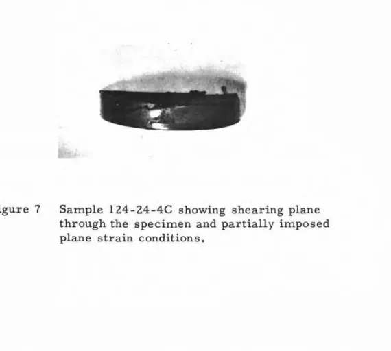
Figure 7
.
-.
"
..
セ N B
,-..
-L セ
Sample l24-24-4C showing shearing plane through the specimen and partially imposed plane strain conditions.
Figure 8 Left: Bearing plate with Plaster of Paris keys still attached to blade s
Right: Specimen after test showing outer limits of shearing plane s , (Shearing stre s s acting from L to R).
0.7 0.6 0.5 N 20.4 u ... C) ::..:::
..
セ\-.1
0.3 0.2o
Max.7:
20 A
a
8 Plaster of Paris wafers 20 C,Da
E Steel pin pointsセMML 20E